The Ultimate Guide to Surface Finish Standards: Symbols, Charts, Techniques, & Applications
Surface finish standards establish a common language that upholds uniformity and accuracy.
This article was first published on
jiga.ioSurface finish is a central pillar of manufacturing and engineering, profoundly affecting both aesthetics and functionality. Surface finish can optimize a product’s performance, durability and the user experience and quality.
This article will introduce the art and science of surface finish standards and surface finish symbols. This is a subject where aesthetics and functionality converge, so we will explore the significance of surface finishes from all perspectives.
From mirror polish to intricate textures, we will explore how this crucial aspect of manufacture impacts industries and everyday products alike.

Core properties of surface finish
Surface finish is defined by a range of surface properties, the nature of which may vary with the method by which the surface is generated;
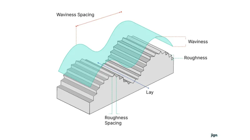
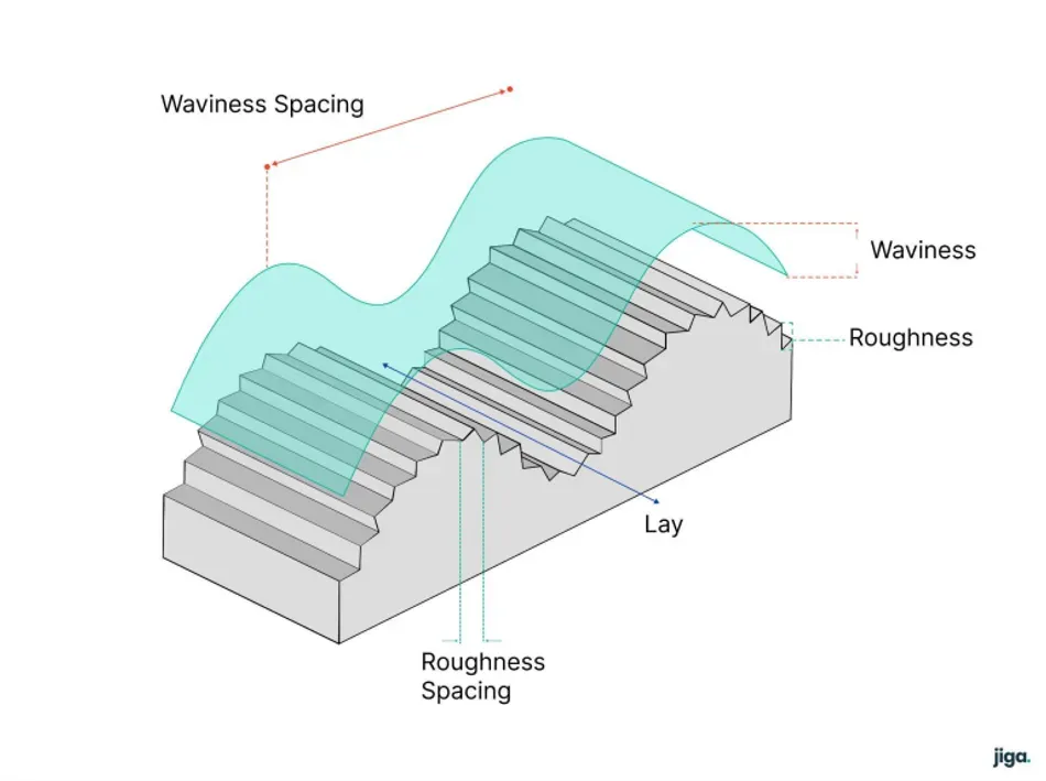
Roughness
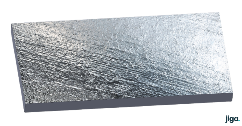
Roughness is the term used to describe the small or microscopic features that make a surface feel granular and abrasive. These features can be so small that the surface has a specular (mirror like) appearance, or they can be larger and random like sand, they can be larger and more orderly and they can be elongated in a machining direction.
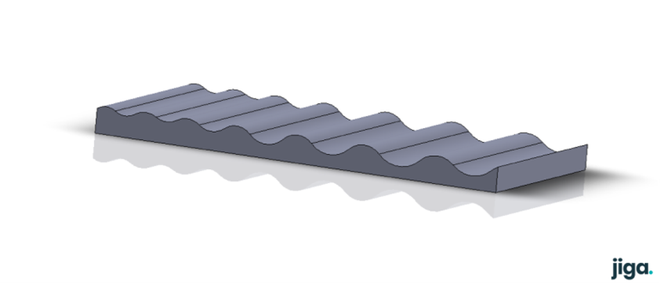
Waviness
Waviness is a commonly used term to denote the larger or macroscopic variations in a surface that can be thought of as flatness. The waviness of a surface will generally be on a larger scale than the roughness.
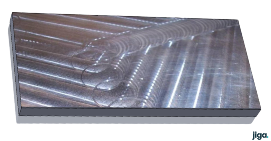
Lay
Lay is used to describe the machining features resulting from the direction of tool/process movement in creating a surface, usually present as extended lines of roughness which can be straight, curved or in closed patterns such as circles, depending on the toolpath.
Why surface finish matters
Functional importance: friction, wear resistance, and sealing
Surface finish carries profound functional importance in a multitude of product aspects, directly influencing friction, wear/chemical erosion resilience and face contact sealing performance.
Friction can be minimized through surface finish and surface material selection, enhancing energy efficiency and minimizing wear on components. In precision machinery, minimized friction facilitates precision, minimizes hysteresis, allows accurate positioning and reduces heat generation.
Wear resistance is boosted by appropriate surface finishes. Microscopic surface roughness provides the initiation points for wear and material degradation. A well-engineered finish resists wear by abrasion and adhesion/microwelding, extending the lifespan of parts and machinery.
Effective sealing, vital for containment and fluid control, heavily relies on surface finish. In applications like gaskets and o-rings, a polished finish at the seal contact point ensures optimal conformance in the seal and prevents leakage. In fixed contact surfaces that require sealing, such as blanking faces in mold or casting tools, the mating surfaces must be sufficiently flat and smooth to provide no meaningful leakage path.
Selecting an appropriate surface finish for an application has critical impacts on both function and aesthetics:
- Performance Optimization
- Functional Requirements
- Material Compatibility
- Aesthetics
- Cost Efficiency
- Consistency and Reproducibility
- Manufacturability
A controversial issue worth discussing.
Surface finish issues in plastic mold tooling can become challenging, when component designs are constrained to limited or zero draft angle in some areas.
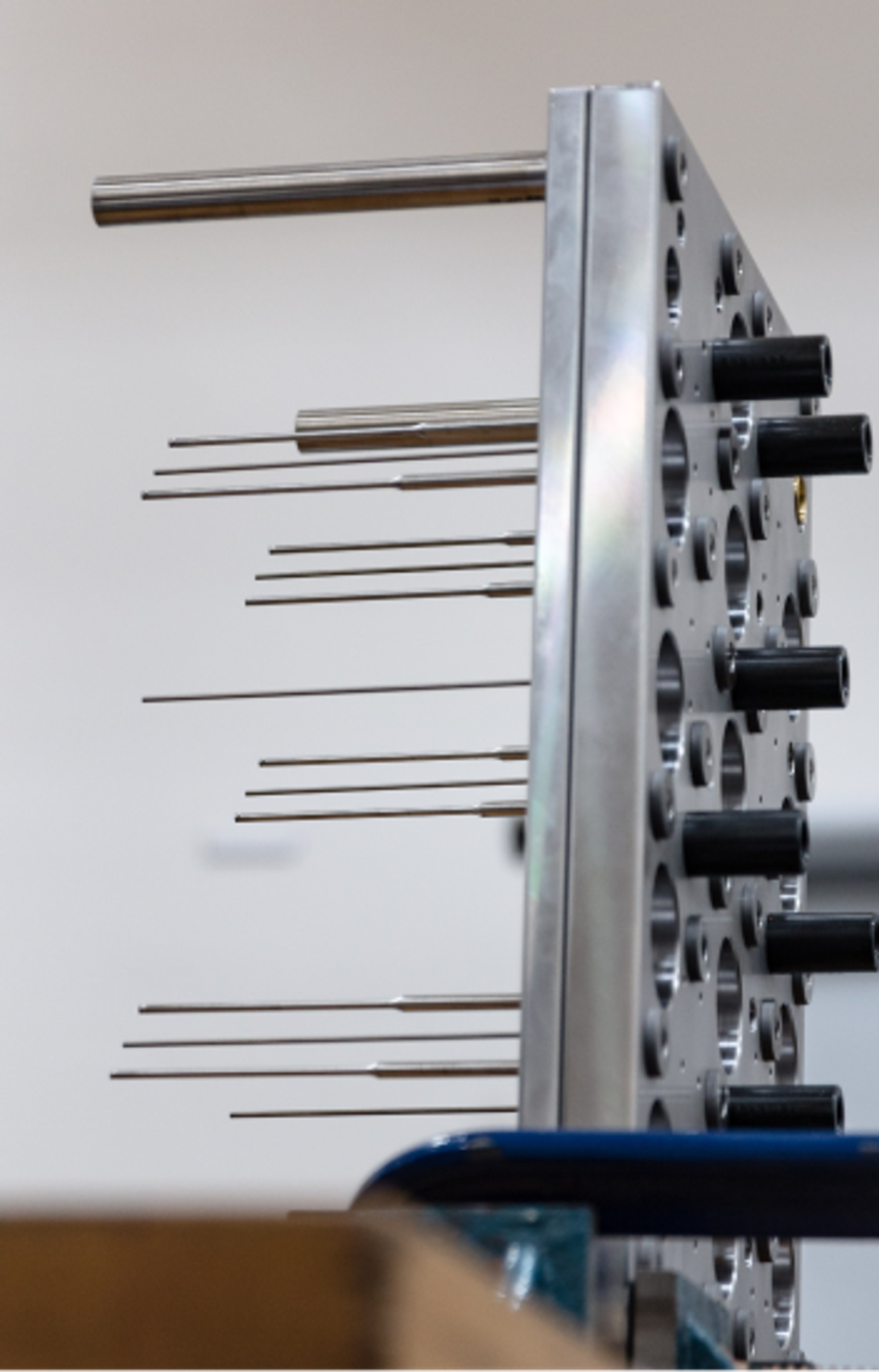
Take the long pins that are used to mold parallel screw-boss holes. These can be and are specified to a mirror finish in tool production, so that the parallel sides of the pin can slide smoothly against the parallel bore of the screw hole they define.
‘Hanging up’ is the condition in which the surface of the pin is stuck to the surface of the bore, at ejection. This can be so bad that sometimes the screw pillar stays in the tool when the part is ejected, torn off and destroyed.
The normal response to this is to use a sleeve ejector that sits around the pin. This ejector pushes directly on the top of the pillar, to encourage the pin in the screw hole to come out despite the minute waviness it may still possess. All good.
But sleeve ejectors suffer a lot of force, and become wear/service points in the tool, because the forces can be quite large.
So the best toolmakers go one step further. The pins are polished to a mirror finish, yes. But the final stage is manual, draw polishing, where the pin is polished along its length, rather than around its circumference, making any residual ‘lay’ longitudinal rather than circumferential and reducing the effect of residual waviness.
Though the surface finish spec is the same on the drawing – the effect on ejection forces, part quality and tool life can be profound. Draw polishing to allow near parallel sections to eject cleanly is more art than engineering.
Aesthetic considerations in product design
Aesthetic considerations of surface finish are central in product appreciation, often defining a product’s visual appeal and brand identity by influencing consumer perception.
Surface finish directly shapes the tactile and visual experience of a product. The choice of textures, whether glossy, matte, or textured, imparts a distinct feel and impression. A sleek polished finish might convey sophistication, while a rugged texture can evoke durability and authenticity.
Color and albedo, from plating/anodizing/painting and substrate texture often define product aesthetic. Variance of finishes within components or at component boundaries can significantly enhance the apparent quality of a product.
Finish, color and texture are a key design language that definitely influence the product appeal, accentuate design details and communicate functionality.
Well executed surface finishes transform products into visually enticing and satisfying objects that resonate with consumers, on both practical and emotional levels.
Impact on subsequent manufacturing processes
Coating and Plating
Paint, powder coating, or electroplating etc. relies on surface preparation. Poor surface finish may degrade adhesion, coverage or coating durability.
Adhesive Bonding
Adhesive bonding processes depend heavily on surface condition. Sufficient roughness and cleanliness are crucial for reliable bonding.
Welding and Soldering
Surface finish influences the quality of welds etc. Clean and properly prepared surfaces lead to better fusion/keying. Rough finish can lead to inconsistencies in the welding process, affecting joint strength and integrity.
Machining and Precision
Machining effort can be increased by initial uneven or rough surfaces, requiring additional material removal.
Surface Coating and Treatment
Surface finishes impact the effectiveness of treatments like shot peening, polishing, alodining, anodizing, nitriding etc. Poor surface preparation and oxide residues can affect the depth of treatments and their resulting benefits.
Assembly and Tolerance
Surface finish directly impacts fine part tolerances and fit during assembly. In transition fits, the surface roughness must be insignificant compared with the shaft clearance, for example.
The quality of finish of a surface often presents a foundation for subsequent manufacturing steps. Effective consideration of surface finish ensures smoother operations, higher product quality, and improved cost-effectiveness.
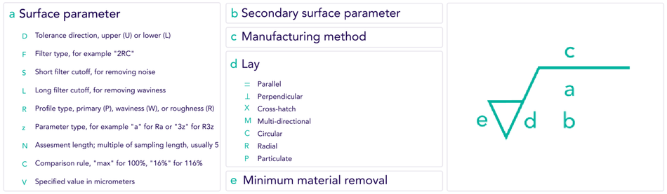
Understanding Surface Finish Symbols
Introduction to the language of surface finish symbols
The language of surface finish symbols (or surface roughness symbols) enables effective communication between designers, engineers, and manufacturers. The symbols offer an unambiguous and standardized specification of surface texture, accepted across all sectors.
The ISO drawing annotations convey information about roughness, waviness/flatness, lay, and other characteristics, to define how smooth or rough a surface should be in a common symbolic language.
Understanding the application and reading of surface finish symbols is pivotal in communicating product design intent and manufacturing outcomes, making surfaces that are consistent in quality, and aligned with the intended functional and aesthetic objectives.
Key symbols and their meanings
Surface finish symbols, imperative in most engineering drawings, convey specific texture requirements for machined or manufactured surfaces.
These are the key surface finish definitions (all are values in μm under ISO drawing standards):
| Ra | The arithmetic average of the absolute values of roughness deviations from the mean line. |
| Rz | The average of the absolute values of the five largest peak-to-valley differences. |
| Rmax | The maximum height of a single roughness peak or valley. |
| Ry | The maximum height of the roughness profile from the highest peak to the lowest valley. |
| Rp | The distance between the highest peak and the lowest valley. |
| Rq | The root mean square (RMS) average of the roughness profile deviations from the mean line. |
| Rv | The maximum depth of a single valley. |
| Rt | The maximum height from the highest peak to the lowest valley. |
These symbols are examples, each representing an approach to defining surface finish. Industry standards and guidelines (such as ISO 1302) offer a deeper understanding of surface information.
Practical examples of how surface finish symbols used in engineering drawings
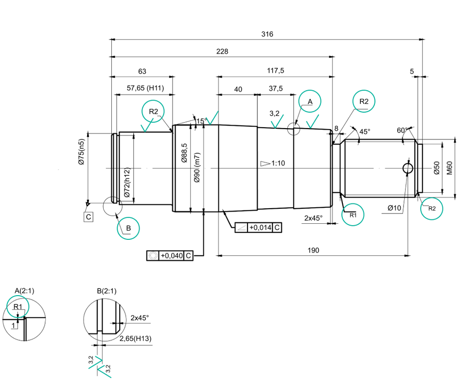
There is a vast array of ways in which surface finish symbols aid in manufacturing. Here are a few examples:
In aerospace manufacturing
A turbine blade’s critical aerodynamic surface may require an Ra value of 0.4 μm (i.e. very smooth) to reduce friction and improve efficiency.
In automotive engineering
An ICE (internal combustion engine) cylinder wall’s Rz value of 3 μm might be specified to ensure optimal oil retention and bore to piston clearance.
In tool and die production
An injection mold cavity’s Rmax value of 8 μm could be indicated for enhanced part ejection, where draft angle is restricted.
A gear tooth’s Rq value of 1.6 μm could ensure proper meshing and durability.
Surface finish symbols empower engineers to define texture needs precisely, aligning design intent with manufacturing reality.
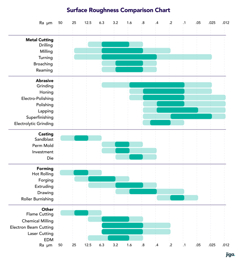
Dive into Surface Finish Charts
Explanation of common charts used in the industry
Surface finish charts in manufacturing provide a graphical representation of surface texture parameters and their corresponding values, aiding in understanding and specifying surface finish requirements:
This chart displays symbols and values corresponding to various roughness parameters. It helps engineers and manufacturers select and interpret requirements easily.
This chart illustrates the relationship between roughness height and wavelength, visualizing the distribution of peaks and valleys on a surface.
Depicting the flatness (or waviness) of a surface, this chart relates to larger irregularities that can influence the performance of components.
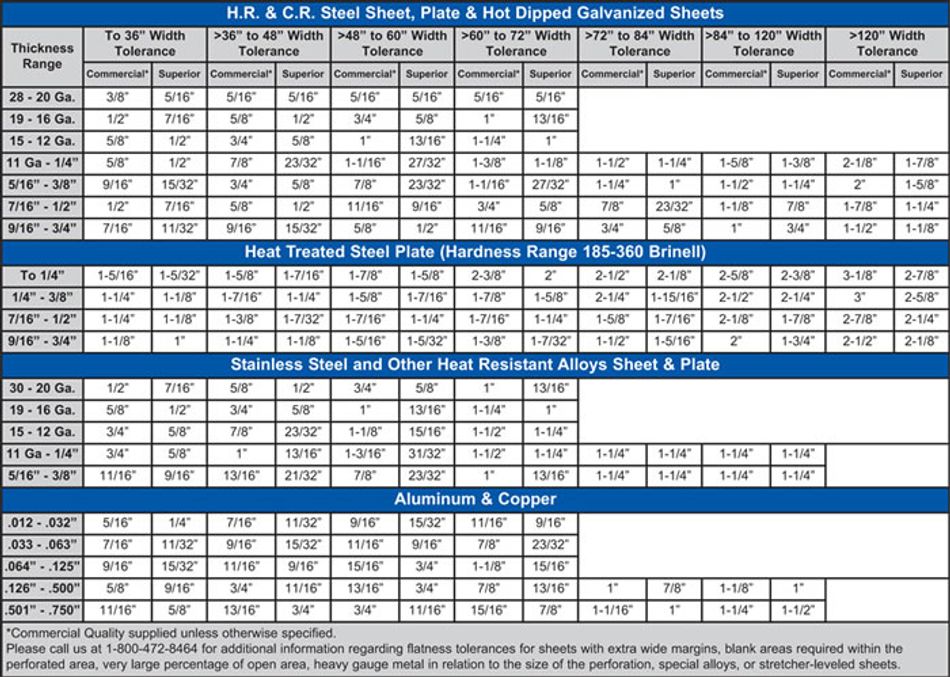
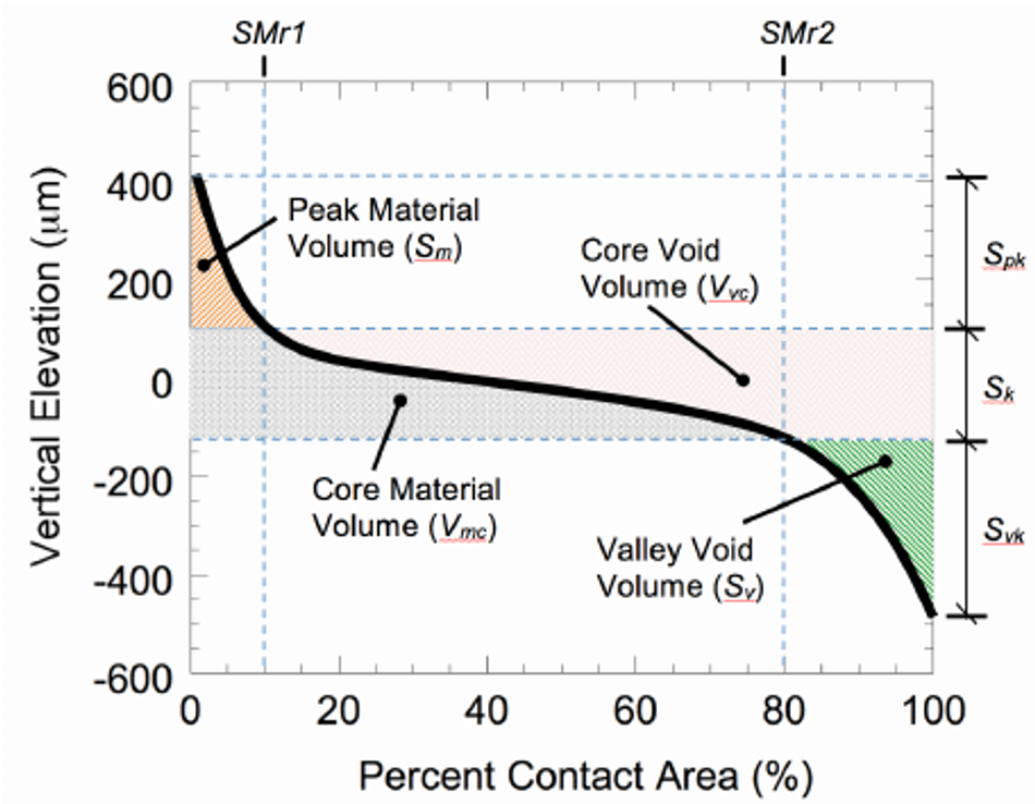
This chart relates to the material ratio parameter that assesses the percentage of the surface profile that lies above or below a specified reference line. It assists in understanding the overall texture of a surface.
These are essential references for precision engineers, designers and manufacturers when communicating, interpreting, and specifying surface finish requirements.
How to read and interpret the data.
Reading and interpreting surface finish data involves understanding the symbols and numerical values and the actual measurements and resultant functional surfaces they represent:
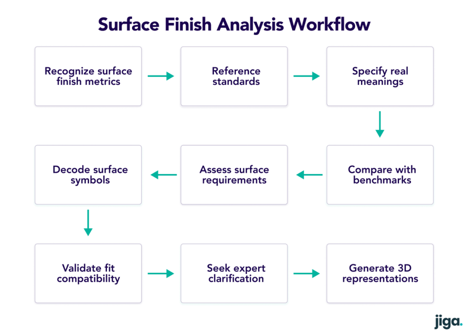
- Identify surface finish parameters and the real meanings of Ra, Rz, Rmax, etc.
- Refer to standards (e.g., ISO 1302) for the definitions and guidelines for these parameters.
- Understand the numerical values and their implications in the real world. Lower values indicate smoother surfaces.
- Symbol interpretation for various actual surface and functional implications, such as roughness, flatness/waviness, lay, etc..
- Contextual considerations, to evaluate the necessary surface qualities and understand valid and in-valid specification.
- Comparative analysis, relative to benchmarks to visualize the texture symbol meaning and assess compliance with specification.
- Consider tolerance and fit, to ensure the surface finish falls within the acceptable range to ensure fit and function.
- If you’re unsure about any aspect of the surface finish data, communicate with the designer, manufacturer, or a surface finish expert. Clarifying doubts can prevent errors.
- Visualization tools generate 3D representations of the surface finish based on the data. This can help develop better understanding.
Surface Finish Standards: An Overview
The surface finish standards maintain consistency and precision across diverse manufacturing and engineering processes. These standards provide universal guidelines for measuring and specifying surface texture, to facilitate conformity and uniformity within and between divergent products.
Adherence to standards allows manufacture of consistent results, regardless of supplier or equipment. This is paramount for service parts, assembly compatibility and seamless integration/aesthetics within complex systems.
The intrinsic precision of surface finish standards ensures that products are made as the design intends. Parameters for roughness, flatness and other texture characteristics eliminate variations.
Surface finish standards establish a common language that upholds uniformity and accuracy.
International standards vs regional ones
The choice between adherence to international or regional standards for surface finish is a significant consideration, impacting supply chain adaptability and global consistency.
- Harmonized international standards provide a unified framework for specification. They promote consistency across industries and countries so engineers and manufacturers around the world can communicate requirements unambiguously.
- Regional standards may cater to unique and local industrial practices, materials, or preferences. These standards may suit particular local supply chains more closely. However, they can lead to inconsistencies when scaling up or second-sourcing from out-region.
Organizations often align with both, selecting international standards for international interactions and regional standards when catering to local markets – and documenting the equivalence in the product specification documents, to alleviate any potential conflict.
Role of organizations like ISO, ASME, etc.
Organizations like ISO, ASME (American Society of Mechanical Engineers) etc. are crucial in defining and standardizing surface finish parameters and guidelines, supporting innovation and educating suppliers and the market in the how-to of surface finish.
- Standardization: ISO, ASME and others, define the standards for defining surface finish parameters in manufactured goods. The standards provide uniform language, symbols, and measurement methods between divergent industries and across geographic boundaries.
- Global guidelines and specifications: Such organizations publish guidelines and specifications that define how to measure, analyze, filter and interpret surface finish data correctly.
- Quality assurance: ISO and ASME standards enable product inspection by setting benchmarks for surface finish.
- Innovation and research: They facilitate collaboration and research among industry experts to integrate/disseminate technological advancements in updated best-practices and tools.
- Education and training: They offer training programs and resources to facilitate professionals in understanding and implementation of surface finish standards effectively.
Evolution of standards over time
The evolution of surface finish standards has always been driven by the need for precise communication, quality standard, and technological advancement in manufacturing. Early standards in the late 19th and early 20th Centuries relied on subjective descriptions and visual comparisons. The latter 20th Century saw the establishment of increasingly comprehensive standards like ISO 1302. The standards continue to evolve to include parameters for flatness/waviness, lay and to integrate increasingly advanced 3D measurement methods. This includes integration of digital design and manufacturing technologies, reflecting the pursuit of accuracy, efficiency, and effective cross-industry communication in specifying and assessing surface finish.
Common Mistakes and Pitfalls
Over-specifying finish requirements.
Over-specifying finish leads to increased manufacturing costs and limits the pool of available suppliers to those who can meet the higher capability demanded that’s perhaps not required.
This also introduces complexity in quality control and measurement, potentially causing additionally wasteful difficulties.
Misinterpreting symbols and standards.
Misinterpreting surface finish symbols and standards can lead to unintended outcomes in manufacturing:
- Components might be produced with incorrect textures.
- Miscommunication results in rework and delays.
- Incorrect measurements can lead to non-compliance.
Precise and correct understanding and application of surface finish symbols and standards is essential to ensure products meet design intent.
Failing to consider manufacturing capabilities.
The failure to properly reflect supplier capabilities in surface finish of parts is a common result of a relaxed and ‘good enough’ approach, in price competitive situations.
This can only be countered by:
- Design team handover to manufacture is thorough.
- Quality management systems (QMS) that create reliable implementations
- Selection of suppliers who know their capabilities and price realistically.
Miscommunication
Miscommunication is a recurring challenge in surface finishing. Often, the exchange of unclear or incorrect details can lead to errors or confusion. For engineers, having a platform like Jiga can be instrumental. Jiga bridges the gap between suppliers and engineers, enhancing communication and ensuring that both parties are on the same page. By fostering clear conversations and streamlining information exchange, potential issues can be greatly reduced.
Conclusion
Understanding surface finish is a key aspect of product development, prototyping, manufacturing handover and quality management. Without sufficient understanding, opportunities for product improvement and cost saving will be missed or neglected.