The Seebeck Effect: Principles, Materials and Applications
The Seebeck effect converts a temperature difference across a conductor or junction of two materials into a voltage. This article reviews the physics, Seebeck coefficients, thermoelectric materials, figure of merit, thermocouples, and generator design.

27 Jul, 2026. 17 minutes read

Conceptual illustration of the Seebeck effect
Key Takeaways
A temperature gradient across a conductor, or across a junction of two dissimilar materials, drives charge carriers to diffuse from the hot end toward the cold end; the resulting open-circuit voltage is the Seebeck effect.
The Seebeck coefficient (thermopower) is defined as S = -dV/dT and is expressed in volts per kelvin. Typical values range from a few microvolts per kelvin in metals to hundreds of microvolts per kelvin in good thermoelectric semiconductors [2].
The sign of the Seebeck coefficient reveals the dominant carrier type: negative for n-type (electron) conductors and positive for p-type (hole) conductors [2].
Thermocouples combine two materials with different Seebeck coefficients to measure temperature; their output voltage follows V(AB) = (S(A) - S(B)) × delta T, with standard types K, J, T, and E delivering tens of microvolts per kelvin [4].
The Peltier and Thomson effects are closely related thermoelectric phenomena, and the Kelvin relations connect all three coefficients thermodynamically [6].
High-efficiency thermoelectric generators require a large Seebeck coefficient, high electrical conductivity, and low thermal conductivity together; the figure of merit ZT = S² × sigma × T / kappa guides material selection [5].
Introduction
The Seebeck effect is the origin of the electrical voltage generated when a temperature difference is imposed across a conductor or across a junction of two dissimilar conductors. First observed by Thomas Johann Seebeck in 1821, the phenomenon underpins thermocouples, thermoelectric generators, and a growing family of energy-harvesting technologies. Seebeck's original experiments involved heating one junction of a copper-bismuth loop and watching a nearby compass needle deflect; he interpreted the effect as a form of magnetic polarization produced by a temperature difference, calling it thermomagnetism [1]. Hans Christian Ørsted later recognized that Seebeck had, in fact, created a purely electrical circuit driven by a thermal gradient [1].
In modern terms, the Seebeck effect describes the emergence of an open-circuit voltage when charge carriers diffuse from a hot region of a material toward a cold region. The proportionality constant relating that voltage to the temperature difference is the Seebeck coefficient, and it is the single most important material parameter in thermoelectric engineering. The effect is reversible and thermodynamically linked to the Peltier effect: when a current is forced through a junction, the junction absorbs or releases heat rather than generating a voltage.
Consider a Type K thermocouple, which has a sensitivity of approximately 41 µV/°C near room temperature [4]. For a measurement junction held 60 °C above the reference junction, the expected output voltage is
V = 41 microV/degC × 60 degC = 2,460 microV = 2.46 mV
This small, millivolt-level signal must be amplified and compared against a stable cold-junction reference before it becomes a usable temperature reading, which is why signal conditioning and cold-junction compensation are central themes later in this article. This article examines the fundamental physics of the Seebeck effect, reviews thermoelectric materials and coefficients, compares related thermoelectric effects, details practical devices and applications, and outlines directions for future research.
What Is the Seebeck Effect?
At its core, the Seebeck effect converts a thermal gradient directly into an electrical potential difference, without any moving parts. When one end of a conductor is hotter than the other, the charge carriers at the hot end carry more kinetic energy on average and diffuse toward the cooler end faster than carriers diffuse in the opposite direction. This net diffusion builds up an internal electric field that opposes further diffusion until the system reaches a steady, open-circuit voltage.
A useful analogy is to picture the conductor as a crowded room that is warmer on one side than the other. People (the charge carriers) naturally drift from the crowded, energetic side toward the calmer, cooler side. As they accumulate on the cool side, a subtle social pressure builds that resists further drift, similar to the way an internal electric field opposes further carrier diffusion in a real conductor. The resulting equilibrium, not the drift itself, is what a voltmeter reads as the Seebeck voltage.
Because the effect depends on how easily carriers move in response to both a temperature gradient and an electric field, its magnitude and sign are tied to the electronic structure of the specific material, which is why the Seebeck coefficient varies so widely between metals, semimetals, and doped semiconductors. Engineers who work with temperature sensors will already be familiar with a closely related technology: the thermistor, whose resistance-based operation is often compared with that of Seebeck-effect thermocouples.
Recommended reading: Thermistor vs Thermocouple: Which Temperature Sensor Suits Your Engineering Needs?
Physics of the Seebeck Effect
Carrier Diffusion and Electromotive Force
When one end of a conductor is hotter than the other, carriers at the hot end possess higher kinetic energy and diffuse toward the cold end. This diffusion establishes an internal electric field that drives carriers back toward the hot end until a steady state is reached, and the resulting electric potential difference is the Seebeck voltage. Microscopically, the magnitude and sign of this voltage depend on how the electronic conductivity varies with carrier energy and on which carrier type dominates conduction. In metals and degenerate semiconductors, the Seebeck coefficient can be approximated using the Mott relation, which links it to the derivative of electronic conductivity evaluated at the Fermi level. In nondegenerate semiconductors, the coefficient instead scales with the ratio of average carrier energy to the thermal energy k(B) × T.
Definition of the Seebeck Coefficient
The Seebeck coefficient, also called thermopower or thermoelectric power, quantifies the voltage produced per unit of temperature difference. Formally:
S = - dV / dT [V / K]
where dV is the differential open-circuit voltage resulting from a differential temperature dT. The negative sign follows the convention that a positive temperature gradient produces a negative voltage for n-type conduction. Experimental measurements typically report S in microvolts per kelvin (µV/K). For a thermocouple made of materials A and B, the measurable Seebeck coefficient is the difference between the two legs:
S(AB) = S(A) - S(B) V(AB) = (S(A) - S(B)) × delta T
So the voltage between the free ends is proportional to both the coefficient difference and the applied temperature difference.
Sign and Magnitude: Metals vs. Semiconductors
Seebeck coefficients of most metals lie between 1 and 10 µV/K [2]. Metals such as copper, gold, and silver exhibit small positive coefficients because electrons carry charge in a nearly free-electron-like band; metals such as bismuth and lead show negative coefficients that reflect hole-like behavior in their band structure. Good thermoelectric semiconductors, such as bismuth telluride (Bi₂Te₃) and lead telluride (PbTe), reach Seebeck coefficients of hundreds of microvolts per kelvin [5]. In semiconductors, doping controls carrier type directly, the same n-type versus p-type distinction used throughout semiconductor device design: n-type dopants yield negative S, while p-type dopants yield positive S [2]. Typical n-type Bi₂Te₃ exhibits S of approximately -170 µV/K, while p-type Bi₂Te₃ shows approximately +160 µV/K [5]. Because S depends on the energy derivative of the electronic density of states, it can be tuned through doping level, band engineering, and nanostructuring. In practice, a higher Seebeck coefficient usually accompanies lower electrical conductivity, so thermoelectric materials development is fundamentally a balancing act between these two competing requirements.
Recommended reading: N-Type Vs P-Type: Difference Between P-Type and N-Type Semiconductors
The table below lists representative Seebeck coefficients for common metals, alloys, and a thermoelectric semiconductor. Values vary with temperature and purity, but they illustrate the orders of magnitude relevant to engineering design.
Material | Typical Seebeck coefficient (µV/K) | Notes |
Copper (Cu) | +1.5 to +2.0 | Positive, low thermopower; standard reference material |
Aluminum (Al) | +1.5 to +2.0 | Similar to copper |
Gold (Au) | +1.5 to +2.5 | Noble metal with very small S |
Iron (Fe) | +2.0 to +3.0 | Metallic, positive S |
Nickel (Ni) | +5.0 to +6.0 | Larger positive thermopower |
Platinum (Pt) | +5.0 to +6.0 | Used in noble-metal thermocouples |
Bismuth (Bi) | -50 to -100 | Negative S; semimetal with high thermopower |
Lead (Pb) | -10 to -20 | Negative S |
Constantan (Cu-Ni alloy) | +30 to +60 | High S; used as the negative leg in many thermocouples |
Bi₂Te₃ (thermoelectric alloy) | +100 to +250 | High S; figure of merit optimized near room temperature |
These data show that thermoelectric alloys provide Seebeck coefficients roughly an order of magnitude larger than those of common metals. A higher S enhances voltage output, but successful thermoelectric devices must also account for electrical and thermal conductivity, as discussed in the next section.
Microscopic Interpretation
The sign of S follows directly from carrier diffusion. In an n-type semiconductor, electrons diffuse from the hot side to the cold side, leaving positive charge behind at the hot end and creating a negative voltage at the cold end, so S is negative. In a p-type material, holes move toward the cold side, leaving negative charge at the hot end and producing a positive voltage at the cold end, so S is positive [2]. The magnitude of S reflects how strongly the density of electronic states changes near the Fermi level: a steep energy dependence yields a larger thermopower. For metals, whose density of states is nearly constant near the Fermi level, S stays small; for narrow-bandgap semiconductors with strong energy filtering, S can reach hundreds of microvolts per kelvin.
Thermoelectric Materials and Figure of Merit
Power Factor and Figure of Merit
Thermoelectric devices convert heat to electricity through the Seebeck effect, or pump heat through the Peltier effect, and their efficiency is governed by the dimensionless figure of merit ZT. For a single thermoelectric leg, the constant-property approximation defines:
ZT = (S² × sigma × T) / kappa
where S is the Seebeck coefficient, sigma is the electrical conductivity, T is the absolute temperature, and kappa is the thermal conductivity, which includes both lattice and electronic contributions [5]. The numerator S² × sigma is called the power factor, and it quantifies how much electrical power a material can produce per unit of heat flow. Maximizing ZT requires a high Seebeck coefficient, high electrical conductivity, and low thermal conductivity simultaneously, a combination that is rarely found in a single material because raising carrier concentration to increase sigma usually lowers S and raises the electronic contribution to kappa. Strategies used to enhance ZT include band engineering to increase valley degeneracy, energy filtering to boost S, alloying and nanostructuring to scatter phonons and reduce lattice thermal conductivity, and carefully optimizing carrier concentration to balance S against sigma [5].
Thermoelectric Material Families
The search for high-ZT materials has produced several established and emerging classes, summarized in the table below.
| Material Family | Typical operating range | Approximate ZT | Notes |
Bismuth telluride (Bi₂Te₃) and alloys | Near room temperature | ~1 | S ~150-200 µV/K; alloying with antimony or selenium tunes carrier concentration |
Lead telluride (PbTe) | 500-700 K | ~1.5 | Na (p-type) or I (n-type) doping plus nanostructuring; toxicity motivates alternatives |
Skutterudites (CoSb₃ with fillers) | ~800 K | ~1.2 | Rattling filler atoms scatter phonons and lower thermal conductivity |
Half-Heusler alloys | Mid-to-high temperature | 0.8-1 | Mechanically robust; band convergence and resonant doping improve performance |
Silicon-germanium (SiGe) | 800-1200 K | ~1 | Used in space RTGs; heavily doped alloys |
Emerging materials | Varies | Under development | Oxide thermoelectrics (Ca₃Co₄O₉), organic semiconductors, 2-D materials such as MoS₂ |
Measuring Thermoelectric Properties
Accurately determining S, sigma, and kappa is essential for assessing candidate semiconductor materials. Four-probe techniques measure electrical resistivity, laser-flash or steady-state methods determine thermal conductivity, and Seebeck coefficient measurements use either integral or differential methods [1]. Because these properties vary with both temperature and doping level, measurements taken across the intended operating range are what actually guide device design, rather than a single room-temperature data point.
Recommended reading: What is a Semiconductor? A Comprehensive Guide to Engineering Principles and Applications
Thermocouples and Temperature Sensing
Operation Principle
A thermocouple consists of two dissimilar conductors joined at a measurement junction. When the junction and the free ends sit at different temperatures, the Seebeck voltage generated along each conductor differs, so a net voltage develops between the free ends. The measured voltage equals the temperature difference multiplied by the difference between the Seebeck coefficients of the two materials:
V(AB) = (S(A) - S(B)) × delta T
Because only the difference in Seebeck coefficients matters, thermocouple voltages are always measured relative to a reference junction, typically held at a known temperature. Modern instrumentation incorporates cold-junction compensation to account for ambient variations at the point where the thermocouple wires connect to copper measurement leads.
Thermocouple Types and Sensitivities
Base-metal thermocouples (types E, J, K, N, T) use inexpensive alloys and cover temperatures from cryogenic conditions up to roughly 1300°C, while noble-metal types (R, S, B) cover higher temperature ranges but produce smaller Seebeck coefficients. In general, base-metal thermocouples have Seebeck coefficients between 30 µV/°C and 80 µV/°C. Analog Devices provides typical sensitivities at 25°C, summarized below relative to copper leads [4].
| Thermocouple type | Typical sensitivity at 25 °C |
E | ~61 µV/°C |
J | ~52 µV/°C |
K | ~41 µV/°C |
N | ~27 µV/°C |
R | ~9 µV/°C |
S | ~6 µV/°C |
T | ~41 µV/°C |
Applications and Considerations
Thermocouples remain ubiquitous because they are simple, robust, and span wide temperature ranges. They require no excitation current and can be manufactured very small, which suits confined or harsh environments. Their output, however, is nonlinear with temperature and is susceptible to drift and to inhomogeneities that develop along the wire over time. Using the correct extension wire type, keeping junctions clean, and calibrating regularly all help preserve accuracy. Thermocouples are widely used in industrial process control, engine monitoring, kilns, refrigeration systems, and scientific research, and they are frequently compared against resistance-based sensors such as RTDs when engineers select a temperature-sensing technology for a new design.
Recommended reading: RTD vs Thermocouple: A Comprehensive Guide for Engineers
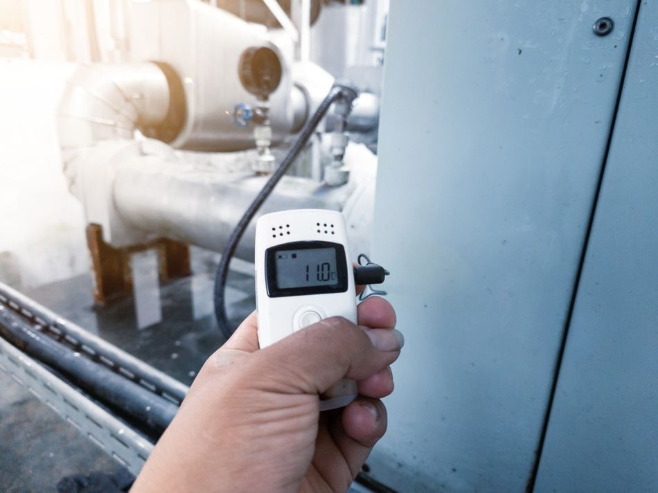
Related Thermoelectric Effects: Peltier and Thomson
Peltier Effect
The inverse of the Seebeck effect is the Peltier effect: when current flows through a junction of two conductors, heat is absorbed or released at that junction. The Peltier heat per unit time is:
Q(P) = Pi(AB) × I
where I is the current, Q(P) is the rate of Peltier heat, and Pi(AB) is the Peltier coefficient of the junction. The Peltier coefficient relates to the Seebeck coefficient through the first Kelvin relation:
π(AB) = (S(A) - S(B)) × T [6]
Meaning the heat transported per unit of charge equals the thermopower multiplied by the absolute temperature. This reciprocity is what allows the same physical junction to function either as a temperature sensor (Seebeck mode) or as a solid-state heat pump (Peltier mode).
Thomson Effect
William Thomson (Lord Kelvin) predicted a third thermoelectric phenomenon in 1851. In a single material carrying an electrical current while a temperature gradient is present, heat is absorbed or evolved along the length of the conductor, with the heat per unit length proportional to both the current and the local temperature gradient. The proportionality constant tau is the Thomson coefficient, and Kelvin's second relation links it to the temperature derivative of the Seebeck coefficient:
tau = T × (dS / dT) [6]
Together, these Kelvin relations enforce thermodynamic consistency among the Seebeck, Peltier, and Thomson effects, so a material's behavior in any one mode constrains its behavior in the other two.
Joule Heating
In addition to the reversible thermoelectric effects described above, any electrical current also generates irreversible Joule heat, I² × R. Thermoelectric devices must be designed to manage this parasitic heat, since it reduces net cooling in Peltier coolers and reduces the net power output of thermoelectric generators. Materials with high electrical conductivity help minimize Joule heating relative to the useful thermoelectric power.
Measuring the Seebeck Coefficient
There are two main experimental methods for measuring the Seebeck coefficient: the integral method and the differential method. In the integral method, a sample rod is subjected to a fixed temperature difference, and the resulting open-circuit voltage is measured, giving an average Seebeck coefficient of S = V / delta T. In the differential method, the ends of the sample are held at slightly different temperatures while a small temperature modulation is applied, and the instantaneous ratio dV/dT yields S directly. The differential method reduces errors caused by temperature-dependent contact potentials and allows absolute measurements when referenced against a known standard [1]. Because thermoelectric signals are microvolt-level, proper thermometry and low-noise instrumentation are essential; in practice, this signal is typically raised to a usable level with a non-inverting amplifier stage chosen for its high input impedance, and measuring the Seebeck coefficient of a material pair requires subtracting the contribution of a reference material, often constantan or platinum.
Recommended reading: Non-Inverting Amplifier Design: Op-Amp Theory, Bandwidth, Noise, and Practical Implementation
Thermoelectric Energy Conversion and Generators
Thermoelectric Generators (TEGs)
Thermoelectric generators convert heat directly into electrical power using the Seebeck effect. A typical module contains many pairs of n-type and p-type semiconductor legs connected electrically in series and thermally in parallel. The hot side attaches to a heat source, and the cold side attaches to a heat sink, so the voltage output is the sum of the individual leg voltages while the current depends on the external load. Maximum power transfer occurs when the load resistance matches the internal resistance of the TEG. Applications include waste-heat recovery in industrial processes and automotive exhaust systems, cogeneration of electricity from biomass or geothermal heat, and powering sensors in remote locations. Radioisotope thermoelectric generators (RTGs) used on deep-space missions such as Voyager and the Mars rovers pair SiGe or PbTe legs with heat from the decay of plutonium-238; their reliability stems directly from having no moving parts.
Efficiency Considerations
The efficiency of a TEG operating between hot and cold reservoirs T(h) and T(c) depends on the average figure of merit ZT of the leg materials and on the applied temperature difference. The maximum efficiency is:
eta = [(T(h) - T(c)) / T(h)] × [(sqrt(1 + ZT(avg)) - 1) / (sqrt(1 + ZT(avg)) + T(c)/T(h))]
where ZT(avg) is evaluated at the average operating temperature of the device. With current materials (ZT ~ 1), conversion efficiencies of 5-7% are typical; higher efficiencies require materials with ZT greater than 2 together with effective system integration. Thermal management, meaning maintaining a large temperature gradient without excessive parasitic heat leakage, is critical to realizing this theoretical efficiency in a real device. Cascaded modules that pair different materials optimized for successive temperature ranges can further improve overall performance.
Energy Harvesting and Wearable Devices
Small thermoelectric harvesters can convert body heat into electricity to power wearable electronics or wireless sensor nodes. Although the available temperature difference is modest, often only a few kelvin, the absence of moving parts and the resulting long service life make the approach attractive for battery-free or battery-assisted designs. Flexible thermoelectric textiles that incorporate polymer composites or thin-film Bi₂Te₃ arrays are under active development, and pairing these harvesters with supercapacitors and power-management circuitry enables genuinely self-sustained sensor nodes.
Recommended reading: Evaluating the Feasibility of Energy Harvesting for IoT Products
Design Considerations for Engineers
Designing a system around the Seebeck effect requires balancing material properties, electrical load, and thermal environment together, rather than optimizing any single parameter in isolation. Material selection means choosing n-type and p-type legs with high Seebeck coefficients, high electrical conductivity, and low thermal conductivity appropriate to the intended temperature range. Thermal management is equally important: good thermal contact at both the hot and cold interfaces, supported by heat sinks or heat exchangers, is what actually maintains the temperature gradient the device depends on. On the electrical side, maximum power transfer occurs only when the external load resistance matches the internal resistance of the thermoelectric device, whereas sensor applications instead call for high-impedance readout to minimize loading of the small thermocouple signal.
Mechanical and chemical stability also deserve early attention, since thermoelectric materials must withstand thermal cycling, oxidation, and mechanical stress over years of service; protective coatings and encapsulation can meaningfully extend operating life. In thermocouple-based systems specifically, accurate cold-junction compensation, whether implemented in hardware or software, and careful noise reduction through shielded and twisted-pair leads together with differential amplification are what ultimately determine whether a design achieves its rated measurement accuracy in the field rather than only on the datasheet. That accuracy is ultimately bounded by the quality of the underlying voltage reference used in the signal-conditioning circuit, since even a well-designed cold-junction compensation scheme inherits any drift or noise present in that reference.
Recommended reading: Voltage Reference: A Survey for Precision Engineers
Common Applications
Beyond thermocouples and dedicated generators, Seebeck-effect devices appear anywhere a temperature difference can be converted into a usable electrical signal or a modest amount of power. In industrial automation, thermocouples feed process controllers and safety interlocks in kilns, furnaces, and chemical reactors. In automotive and aerospace systems, thermoelectric sensors monitor exhaust and engine temperatures, while RTGs and emerging thermoelectric harvesters supply auxiliary power in spacecraft and remote installations where solar power is impractical. In consumer and IoT electronics, small thermoelectric generators and power-management integrated circuits work together to harvest ambient heat for battery-free or battery-assisted sensor nodes.
Recommended reading: PMIC Meaning: Understanding Power Management Integrated Circuits in Modern Electronics
Future Directions
Research aims to push the figure of merit beyond current values through several complementary avenues. Nanostructuring and phonon engineering, including embedded nanoscale precipitates, superlattices, and hierarchical architectures, scatter phonons and reduce thermal conductivity while largely preserving carrier mobility [5]. Band structure engineering, through band convergence, resonant levels, and multivalley band structures, enhances the Seebeck coefficient and power factor together, with Mg₃Sb₂-based materials and half-Heusler alloys as leading examples. High-entropy and complex compounds, such as high-entropy oxides that combine multiple atomic species, offer low thermal conductivity alongside tunable electronic properties.
Flexible and organic thermoelectrics, built from conductive polymers, carbon-nanotube composites, and hybrid perovskites, offer low-temperature processing and mechanical flexibility, though achieving a high power factor in these systems remains a persistent challenge. Finally, system-level integration, combining thermoelectric modules with phase-change materials, heat pipes, or photovoltaic cells, can harvest multiple forms of energy from the same source, while advanced packaging and thermal interface materials reduce parasitic losses. Together, these directions could allow future thermoelectric devices to harvest waste heat at industrial scale, power wearable sensors indefinitely, and enable solid-state refrigeration without moving parts.
Conclusion
The Seebeck effect turns a simple temperature difference into a measurable, and sometimes usable, electrical voltage, and that basic capability underlies technologies as different as industrial thermocouples and deep-space radioisotope generators. Across the materials explored here, from ordinary copper and platinum to engineered bismuth telluride and skutterudite compounds, the same trade-off recurs: a large Seebeck coefficient, high electrical conductivity, and low thermal conductivity rarely coexist naturally in one material, and thermoelectric materials science is largely the pursuit of a better balance among the three.
For practicing engineers, understanding the Seebeck coefficient, the related Peltier and Thomson effects, and the figure of merit ZT is what separates a thermocouple design that merely works from one that is accurate, stable, and repeatable in the field. As waste-heat recovery and battery-free sensing continue to gain importance, the Seebeck effect, first noticed as an odd deflection of a compass needle two centuries ago, remains a quietly essential tool in modern electrical and thermal engineering.
FAQ
What is the Seebeck effect?
The Seebeck effect is the generation of an electrical voltage when a temperature difference is applied across a conductor or a junction of two dissimilar conductors. Carriers diffuse from the hot side toward the cold side, establishing an internal electric field that produces an open-circuit voltage [1]. The voltage is proportional to the temperature difference through the Seebeck coefficient.
How is the Seebeck coefficient defined?
The Seebeck coefficient (thermopower) is defined as S = -dV/dT and has units of volts per kelvin. A positive coefficient means a positive temperature gradient produces a positive voltage; a negative coefficient means the opposite. In practice, S is usually measured in microvolts per kelvin and reported relative to a reference material.
Why are Seebeck coefficients positive for p-type and negative for n-type materials?
In p-type semiconductors, holes are the majority carriers. When the hot end is heated, holes diffuse toward the cold end, leaving negative charge behind and producing a positive voltage at the hot end, so S is positive. In n-type materials, electrons diffuse toward the cold end, leaving a positive charge behind, so the resulting voltage at the hot end is negative and S is negative [2].
What are typical Seebeck coefficients for common materials?
Metals have small Seebeck coefficients, around 1-10 µV/K; for example, copper is roughly +1.5 to +2 µV/K and nickel roughly +5 to +6 µV/K [3]. Semimetals such as bismuth show larger negative values, around -50 to -100 µV/K [3]. Thermoelectric semiconductors such as Bi₂Te₃ exhibit |S| around 170-250 µV/K depending on doping [5]. The sign indicates whether electrons or holes dominate conduction.
How do thermocouples measure temperature?
A thermocouple uses two wires of different materials joined at a measurement junction. When the junction and the free ends sit at different temperatures, the difference in the materials' Seebeck coefficients produces a voltage proportional to that temperature difference. Because the output is small, tens of microvolts per kelvin, cold-junction compensation and amplification are necessary [4]. Standard types (E, J, K, T, and others) cover different temperature ranges with sensitivities between about 6 µV/°C and 61 µV/°C [4].
What is the relationship between the Seebeck and Peltier effects?
The Peltier effect describes heat absorption or evolution when current passes through a junction of two materials. Thermodynamic reciprocity, expressed by the Kelvin relations, states that the Peltier coefficient equals the Seebeck coefficient difference multiplied by the absolute temperature: Pi(AB) = (S(A) - S(B)) × T [6]. This means materials with large Seebeck coefficients also exhibit strong Peltier heating or cooling at their junctions.
What is the figure of merit ZT, and why does it matter?
The dimensionless figure of merit ZT = S² × sigma × T / kappa measures how efficiently a thermoelectric material converts heat to electricity or vice versa [5]. A higher ZT indicates a large power factor (S² × sigma) combined with low thermal conductivity. Materials with ZT close to 1 achieve roughly 5-7% conversion efficiency; values above 2 could enable thermoelectric devices that compete with other conversion technologies.
How is the Seebeck coefficient measured experimentally?
In the integral method, a known temperature difference is applied across a sample, and the resulting voltage is measured, giving an average Seebeck coefficient of S = V / delta T. In the differential method, a small temperature modulation yields S = dV/dT directly, which reduces systematic errors [1]. Both approaches require good thermal contact, calibrated thermometers, and microvolt-sensitive voltmeters.
Can the Seebeck effect power wearable devices?
Yes. Thermoelectric generators can harvest body heat to power low-energy sensors, though the small temperature difference between skin and ambient air, often under 10 K, limits available power. Using materials with high S, flexible form factors, many thermoelectric legs connected together, and efficient power management can deliver microwatt-level power suitable for wearable electronics and biomedical sensors.
References
[1] J. Martin, T. Tritt, and C. Uher, "High temperature Seebeck coefficient metrology," Journal of Applied Physics, vol. 108, no. 12, p. 121101, 2010.
[2] M. Wagner, "Simulation of thermoelectric devices," Ph.D. dissertation, TU Wien, Vienna, Austria, 2007.
[3] Stanford Advanced Materials, "Thermocouples and the Seebeck effect," Stanford Advanced Materials, [Online]. Available: https://www.samaterials.com/content/thermocouples-and-the-seebeck-effect.html
[4] Analog Devices, "Two ways to measure temperature using thermocouples," Analog Dialogue, Analog Devices, Inc. [Online]. Available: https://www.analog.com/en/resources/analog-dialogue/articles/measuring-temp-using-thermocouples.html
[5] H. J. Goldsmid, "Bismuth telluride and its alloys as materials for thermoelectric generation," Materials, vol. 7, no. 4, pp. 2577-2592, 2014.
[6] Northwestern University, "History of thermoelectrics," Dept. of Materials Science and Engineering, Northwestern Univ. [Online]. Available: https://thermoelectrics.matsci.northwestern.edu/thermoelectrics/history.html
in this article
1. Key Takeaways2. Introduction3. What Is the Seebeck Effect?4. Physics of the Seebeck Effect5. Thermoelectric Materials and Figure of Merit6. Thermocouples and Temperature Sensing7. Related Thermoelectric Effects: Peltier and Thomson8. Measuring the Seebeck Coefficient9. Thermoelectric Energy Conversion and Generators10. Design Considerations for Engineers11. Common Applications12. Future Directions13. Conclusion14. FAQ15. References