Surface Finish: Parameters, Standards, and How to Specify It
Surface finish decides whether a bearing seizes, a weld bonds, or a shaft survives its fatigue life. This guide covers what it is, its parameters, and how to specify it.

Last updated on 26 Sep, 2026. 11 minutes read
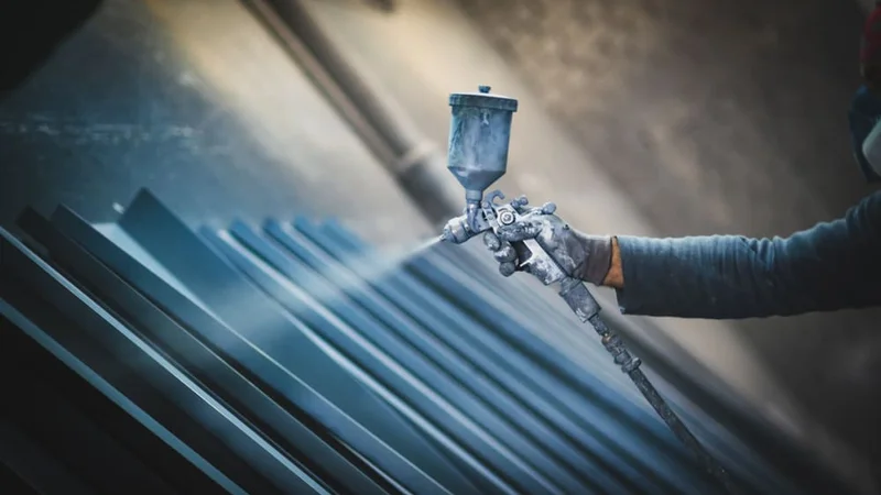
Surface finishes can be altered with methods like coating and conversion
Key Takeaways
Surface finish (surface texture) has three constituents: roughness, waviness, and lay. ASME B46.1-2019 defines them.[1][2]
Ra is an average, so it hides peaks. Two surfaces with identical Ra values can behave very differently in service.[2][12]
The ISO profile standards were replaced in December 2021. ISO 1302 and ISO 4287 are both withdrawn, superseded by the ISO 21920 series.[8][9][11]
Smoother is not automatically better. In one bearing-steel study, wear resistance peaked at an intermediate roughness rather than at the smoothest surface tested.[10]
What Surface Finish Means
Surface finish, also called surface texture, is the set of fine geometrical irregularities left on a surface by the process that made it. ISO 21920-2 defines surface texture as the “geometrical irregularities contained in a scale-limited profile,” and notes that it excludes irregularities contributing to the form or shape of the profile.[5]
Form error (a shaft that is bent, a face that is not flat, a molded part showing warping) is a separate characteristic from surface finish, measured differently and toleranced separately.
Surface defects are a third category again. Isolated scratches, pores, and inclusions are surface imperfections rather than texture. The superseded ISO 1302 standard states that requirements for surface imperfections such as pores and scratches “cannot be specified using surface texture parameters,” and it refers instead to ISO 8785.[8]
ASME B46.1-2019 splits surface texture into three constituents.[1] Its definitions are worth reading exactly, because casual use tends to blur them.
Constituent | ASME B46.1-2019 definition | What causes it |
Roughness | “The finer spaced irregularities of the surface texture that usually result from the inherent action of the production process or material condition.” | Tool marks, grit, feed rate, the cutting action itself |
Waviness | “The more widely spaced component of the surface texture.” | Machine or workpiece deflection, vibration, chatter |
Lay | “The predominant direction of the surface pattern, ordinarily determined by the production method used.” | The kinematics of the process: turning leaves circular lay, surface grinding leaves parallel lay |
Roughness, waviness, and lay are separated from one another by filtering, not by measuring different things. The same profile trace yields all three, depending on which spatial wavelengths you keep.[2]
Recommended reading: Measuring Surface Roughness: A Comprehensive Guide
Why Surface Finish Matters
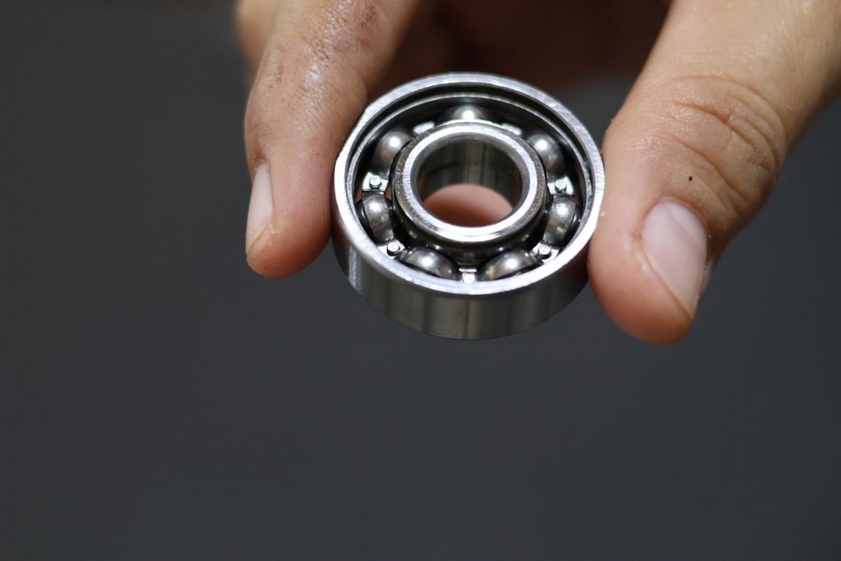
Surface finish is a functional specification. It affects fatigue life, friction, wear resistance, corrosion behavior, sealing, and adhesion.
Fatigue life
Surface irregularities act as stress concentrations, and fatigue cracks start at the surface.
In a study of 42CrMo steel tested in bending fatigue at 5400 N·m, fatigue life fell sharply as roughness increased. The authors concluded that “the fatigue lives decrease gradually with the increase of the height parameters of surface topographies,” and that height parameters are “the most significant roughness parameters to characterize the fatigue performance.”[6]
Surface roughness (Ra) | Fatigue life (reversals) |
≈ 0.1 µm | 906,400 to 1,306,200 |
≈ 1.6 µm | 298,800 to 386,300 |
≈ 3.2 µm | 163,400 to 207,400 |
Friction and wear
The relationship between surface finish and friction is more straightforward than the relationship between surface finish and wear, and the difference between the two is where most specifications go wrong.
A 2025 study of GCr15 bearing steel under oil lubrication measured both.
Friction rose with roughness, but wear did not follow the same pattern. The paper reports that “the influence of the initial surface finish exhibits a non-monotonic trend, whereby the wear area initially diminishes and then enlarges with further increases in roughness.”[10]
The explanation for the results was that a slightly rough surface helped to trap lubricant on the surface of the bearing.[10] For a lubricated sliding surface, then, specifying the smoothest finish you can afford is not automatically the right call, because the valleys do useful work.
Corrosion, adhesion, and conductivity
Rougher surfaces present more area and more crevices, which affects corrosion resistance and the durability of protective layers.
Coating and plating processes depend on surface preparation: adhesion of powder coating or paint generally requires a controlled surface profile rather than a polished one, which is why bead blasting is a common pre-treatment.
Electrical contact behavior is likewise sensitive to real contact area, which surface texture governs.
These relationships are well established in practice, though the specific thresholds are process and material dependent and no single figure applies across them.
Surface Finish Parameters
Ra (roughness average, also called arithmetic mean deviation) is the most widely specified surface finish parameter. ASME B46.1-2019 defines it as “the average of the absolute values profile height deviations recorded within the evaluation length, L, and measured from the mean line.”[2]
. However, an average does not always adequately describe a surface, as the Ra value is lower than the actual height of the roughness variations.[12] A surface with a few deep scratches and a surface with uniform fine tool marks can return the same Ra value while behaving completely differently in a seal groove or under fatigue loading.
That is why drawings often specify a peak-sensitive parameter alongside Ra.
Parameter | What it measures | When to use it |
Ra | Arithmetic mean of absolute deviations from the mean line | General control, process monitoring, the default on most drawings |
Rq (Rms) | Root mean square of the same deviations; squaring weights larger deviations more heavily | Optical surfaces, and where statistical treatment is wanted. Often quoted as Rms |
Rz | Average maximum height, built from peak and valley heights within each section | Sealing faces, fatigue-critical surfaces, anywhere isolated peaks and valleys matter |
ISO 21920-2 organizes its parameters into height, spatial, hybrid, material ratio, and feature families, and defines more than the handful in routine use, including skewness and kurtosis of the height distribution.[5]
Because Ra averages absolute deviations from the mean line and Rz is constructed from peak and valley heights, the two describe different features of the same surface profile. Any conversion between them is an approximation whose accuracy depends on the shape of the profile.
Units: micrometers, microns, and microinches
Surface finish values are quoted in micrometers (µm) in metric practice and in microinches (µin) on some drawings originating in the United States. 1 µin is 0.0254 µm. Older drawings and some instrument displays still say microns, which is the same unit as micrometers under a superseded name.
Common imperial callouts are 125, 63, 32, and 16 µin, which correspond to roughly 3.2, 1.6, 0.8 and 0.4 µm. Note that a Ra of 32 means a moderately machined surface in microinches but an unusually rough one in micrometers.
Profile versus areal parameters
Ra, Rq, and Rz are profile parameters: they come from a single traced line across the surface. Areal parameters, written with an S prefix (Sa, Sq, Sz), come from a measured area and are defined in the ISO 25178 series.[3][5]
A single trace can miss features that an areal scan catches, particularly on surfaces with directional or patterned texture.
Recommended reading: Ra vs Rz: Understanding Surface Roughness Parameters in Engineering
Sampling Length, Evaluation Length, and Filtering
This is perhaps the area of surface finish specification that causes the most disputes between supplier and customer.
A profiling instrument samples height data over several distinct lengths, defined in ASME B46.1-2019:[2]
Traverse length: The “total length of travel of the instrument on the surface” which must be longer than the evaluation length to allow for end effects.
Evaluation length: The “length used to evaluate the profile, after discarding a given distance at the beginning and end of the profile to account for end effects.”
Sampling length: The “length in the direction of the X-axis used for identifying the widest irregularities that are of interest for the profile.” When a filter is used, the roughness long wavelength cutoff equals the roughness sampling length.
The roughness long wavelength cutoff (λc) “attenuates longer wavelengths to yield the roughness profile,” while the roughness short wavelength cutoff (λs) removes “fine asperities or noise from the roughness profile.”[2]
Changing this cutoff changes the roughness and waviness values. ASME’s example takes one measured profile and filters it three ways:[2]
Cutoff λc | Ra | Waviness height |
0.8 mm | 0.057 µm | 0.092 µm |
0.25 mm | 0.044 µm | 0.204 µm |
0.08 mm | 0.028 µm | 0.325 µm |
The same physical surface returns a Ra value that differs by a factor of two depending on a setting. A surface finish callout without a cutoff is therefore incompletely specified, and a supplier and a customer measuring the same surface can legitimately disagree.
When the drawing does not specify the cutoff, B46.1-2019 provides guideline values. These are selected from measured Ra for non-periodic profiles (ground, milled, bead blasted) or from RSm for periodic profiles (turned, shaped).[2]
Ra (µm) | RSm (mm) | Cutoff λc (mm) | Evaluation length L (mm) |
up to 0.02 | 0.01 to 0.04 | 0.08 | 0.40 |
0.02 to 0.10 | 0.04 to 0.13 | 0.25 | 1.25 |
0.10 to 2.0 | 0.13 to 0.40 | 0.80 | 4.0 |
2.0 to 10.0 | 0.40 to 1.3 | 2.5 | 12.5 |
over 10.0 | 1.3 to 4.0 | 8.0 | 40.0 |
The 0.8 mm cutoff covers the Ra band from 0.10 to 2.0 µm, which is where most machined parts sit, and that is why 0.8 mm is the default in workshops.
How Surface Finish Is Measured
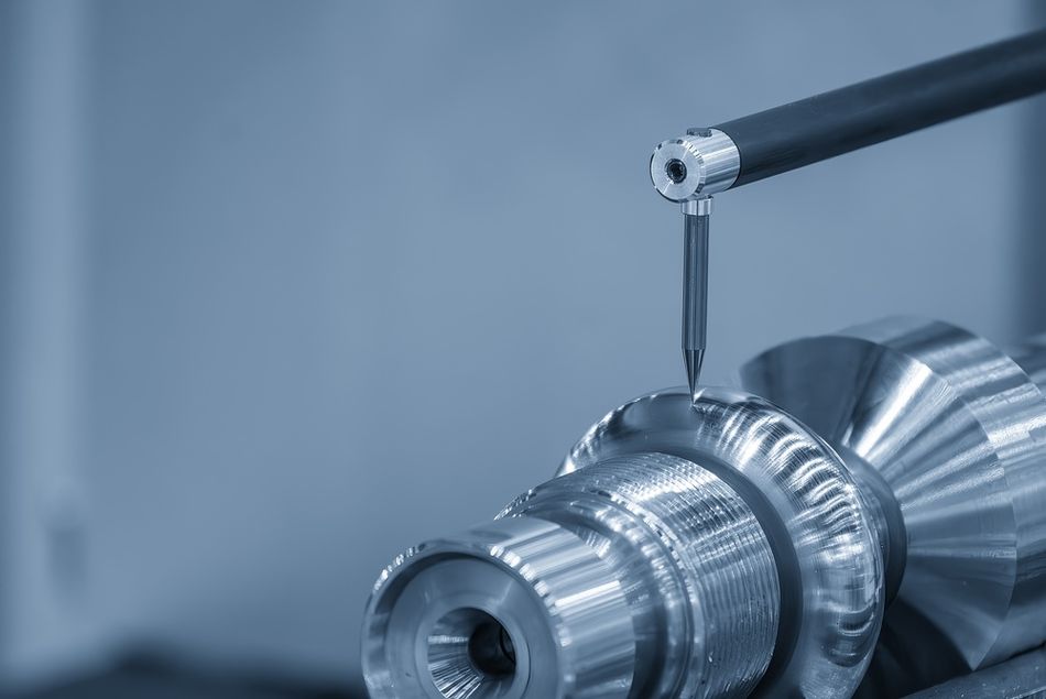
Contact stylus instruments are the workhorse of surface finish measurement. A stylus of known tip radius is drawn across the surface at fixed speed, and height data is recorded at a set sampling interval as the tip follows the surface irregularities.[2] These instruments, commonly called profilometers, produce the surface profile from which Ra and the other parameters are computed.
Non-contact methods use optical interaction rather than a physical tip: focus variation, confocal microscopy, interferometry, and similar techniques. They avoid the risk of scratching soft surfaces, capture areal rather than single-line data, and handle steep features a stylus tip cannot follow.
A stylus and an optical instrument measuring the same part may not agree, because they are interrogating differently defined surfaces.
Portable skidded profilometers are useful on the shop floor, since they can be brought to a large part instead of the part being brought to a bench instrument. The skid acts as a mechanical filter of its own, which is a further reason two measurements of one surface can disagree.
Comparator blocks remain useful for shop-floor triage: you compare a machined part against a reference specimen by eye and fingernail. They tell you whether a surface is roughly right, not whether it meets a toleranced callout.
Reading a Surface Finish Callout
Surface finish symbols carry the specification onto the drawing. The root symbol for surface finish (√) has three variants: an open form that does not give any constraint, a closed triangle that requires material removal, and a circle that forbids material removal.[7][12]
Information is placed around the symbol by position: the specification string sits below the root symbol, lay direction goes at the bottom right, and complementary information about machining or material goes above the horizontal bar. A small circle at the corner extends the specification to all surfaces around the workpiece.[7]
Lay direction has its own symbol set covering parallel, perpendicular, and crossed grooves, plus M for multidirectional, C for circular, R for radial, and P for particular.[7]
Surface Finishing Processes
Different manufacturing processes leave characteristically different surfaces, and surface finishing processes fall into three broad groups, each with its own texture and lay.
Material removal: Surface grinding, honing, lapping, and polishing progressively refine the surface, each capable of finer results than the last. Deburring removes the burrs left at edges by cutting. In CNC machining, the finish achieved depends on tool geometry, feed, speed, rigidity, and tool wear as much as on the nominal process, which is why the same operation on two machines can produce different tool marks.
Mechanical texturing: Bead blasting produces a uniform matte non-directional texture, typically as preparation for coating or for cosmetic uniformity rather than to achieve a low ra value.
Coating and conversion: Anodizing, powder coating, plating, and painting add a layer. These change corrosion resistance, appearance, and sometimes electrical conductivity, and they inherit and modify the texture of the substrate beneath them, so the pre-treatment finish matters as much as the coating.
Current Standards
Both ISO 1302 and ISO 4287 are withdrawn documents as of 2021.
Withdrawn standard | Covered | Replaced by |
ISO 1302:2002 | Indication of surface texture on drawings | ISO 21920-1:2021 |
ISO 4287:1997 | Terms, definitions and profile parameters | ISO 21920-2:2021 |
ISO 4288 | Specification operators and rules | ISO 21920-3:2021 |
ISO 13565-2:1996 and -3:1998 | Material ratio curve parameters | ISO 21920-2:2021 |
Two particular changes are notable:
Parameters are now computed over the evaluation length instead of sampling length, signalling a change from ISO 4287.[5][4] Peak and pit parameters (Rp, Rv, Rz) are still calculated on section lengths “to avoid unstable results.”[4] Ra, Rz, and Rsk “may show significant differences” between the two standards, while “Rq values are virtually unaffected.”[4]
The default acceptance rule has changed. ISO 21920-1 states that “the maximum tolerance acceptance rule is the default tolerance acceptance rule,” replacing the 16% rule that was the ISO 1302 default.[11] The standard defines three rules: maximum, 16%, and median.[11] Under a max rule, no measured value may exceed the limit, which is a stricter test than the old default.
On the ASME side, B46.1-2019 remains current and has been reaffirmed as R2026.[1] Symbols are covered separately by ASME Y14.36M.[12] Areal texture is covered by the ISO 25178 series, with ISO 25178-2:2021 giving the areal terms and parameters.[3][5]
Conclusion
Surface finish is a functional requirement with consequences for fatigue, friction, wear, and corrosion, and it is specified far more loosely than its cost and effect warrant.
Three things separate a good specification from a costly one: choosing a parameter that matches the function rather than defaulting to Ra, stating the filter cutoff so that the number means the same thing to everyone measuring it, and recognizing that smoother is not a synonym for better.
Frequently Asked Questions
What is the difference between surface finish and surface roughness?
Surface finish (surface texture) is the whole picture and includes roughness, waviness, and lay.[1] Surface roughness is only the finest-spaced component of it.[2] Using the terms interchangeably is common but imprecise, and it matters when waviness is the characteristic actually causing a problem.
What does a 32 surface finish mean?
It is a callout in microinches, meaning Ra 32 µin, which is approximately Ra 0.8 µm. The equivalent bands 125, 63, 32, and 16 µin come from imperial practice and are still common on drawings originating in the United States. Note that a number alone does not specify the filter cutoff or the parameter’s acceptance rule, both of which affect whether a part passes.[2][11]
Is Ra or Rz better?
Neither is better in general. Ra averages deviations across the evaluation length and is a good process-control indicator.[2] Rz is built from peak and valley heights and is the better choice when isolated peaks and valleys drive function, as in sealing or fatigue.[5] Many well-written drawings specify both.
Is ISO 1302 still valid?
No. ISO records ISO 1302:2002 as withdrawn, replaced by ISO 21920-1:2021.[8] ISO 4287:1997 is likewise withdrawn and replaced by ISO 21920-2:2021.[9]
Does a smoother surface always perform better?
No. Friction generally falls as roughness falls,[10] but wear resistance does not follow the same curve. In a lubricated bearing-steel study, the lowest wear occurred at an intermediate Sa of 0.5 µm rather than at the smoothest 0.01 µm surface, because some texture helped retain the lubricant film.[10]
Why do two shops measure the same part differently?
Most often because of filter settings. The same profile can yield an Ra of 0.057 µm at a 0.8 mm cutoff and 0.028 µm at 0.08 mm.[2] Instrument type can also matter, since stylus and optical instruments interrogate differently defined surfaces.[5]
References
[1] American Society of Mechanical Engineers. B46.1 Surface Texture (Surface Roughness, Waviness, and Lay. [Internet]. New York (NY): ASME; 2019 [cited 2026 Sep 25].
[2] American Society of Mechanical Engineers. B46.1-2019 Surface Roughness, Waviness, and Lay reference poster. [Internet]. New York (NY): ASME; 2019 [cited 2026 Sep 25].
[3] Physikalisch-Technische Bundesanstalt. Standards and guidelines for surface metrology. [Internet]. Braunschweig: PTB [cited 2026 Sep 25].
[4] Digital Surf. What are the differences between ISO 4287 and ISO 21920?. [Internet]. Besançon: Digital Surf [cited 2026 Sep 25].
[5] International Organization for Standardization. ISO 21920-2:2021 Surface texture: Profile, Part 2: Terms, definitions and surface texture parameters. [Internet]. Geneva: ISO; 2021 [cited 2026 Sep 25].
[6] Zhu X, Dong Z, Zhang Y, Cheng Z. Fatigue life prediction of machined specimens with the consideration of surface roughness. Materials (Basel). 2021;14(18):5420.
[7] Digital Surf. Surface Metrology Guide: indication of surface texture on technical drawings. [Internet]. Besançon: Digital Surf [cited 2026 Sep 25].
[8] International Organization for Standardization. ISO 1302:2002 Indication of surface texture in technical product documentation. [Internet]. Geneva: ISO; 2002 [cited 2026 Sep 25]. Withdrawn.
[9] International Organization for Standardization. ISO 4287:1997 Surface texture: Profile method, Terms, definitions and surface texture parameters. [Internet]. Geneva: ISO; 1997 [cited 2026 Sep 25]. Withdrawn.
[10] He T, Chen W, Liu Z, Gong Z, Du S, Zhang Y. The impact of surface roughness on the friction and wear performance of GCr15 bearing steel. Lubricants. 2025;13(4):187.
[11] International Organization for Standardization. ISO 21920-1:2021 Surface texture: Profile, Part 1: Indication of surface texture. [Internet]. Geneva: ISO; 2021 [cited 2026 Sep 25].
[12] GD&T Basics. The Basics of Surface Finish. [Internet]. [cited 2026 Sep 25].
in this article
1. What Surface Finish Means2. Why Surface Finish Matters3. Surface Finish Parameters4. Sampling Length, Evaluation Length, and Filtering5. How Surface Finish Is Measured6. Reading a Surface Finish Callout7. Surface Finishing Processes8. Current Standards9. Conclusion10. Frequently Asked Questions11. References