I2C vs SPI vs UART: A Comprehensive Comparison
An In-depth Analysis of Features, Applications, and Selection Criteria for Embedded Systems Design. Discover the Advantages and Limitations of SPI, I2C, and UART for Efficient Data Exchange in Various Scenarios.

Last updated on 15 Jan, 2025. 12 minutes read
No time now? Save for later.
We only use your email to send this link. Privacy Policy.
Introduction
Communication protocols are the backbone of embedded systems, enabling seamless and reliable data exchange between components and devices while optimizing overall system efficiency. I2C, SPI, and UART stand out as three foundational protocols, each with unique characteristics tailored to specific applications. I2C, known for its simplicity and scalability, excels in multi-device environments such as sensor networks. SPI, with its high-speed and full-duplex communication, is ideal for applications requiring rapid data transfer like memory cards. UART, a straightforward protocol, is often used in serial communication with peripherals like GPS modules.
Choosing the right protocol is critical for optimizing system performance, ensuring efficient communication, and minimizing resource consumption. By understanding the distinct features and trade-offs of I2C, SPI, and UART, engineers can make informed decisions that align with their project requirements.
Protocol Basics: What Makes I2C, SPI, and UART Unique?
I2C (Inter-Integrated Circuit)
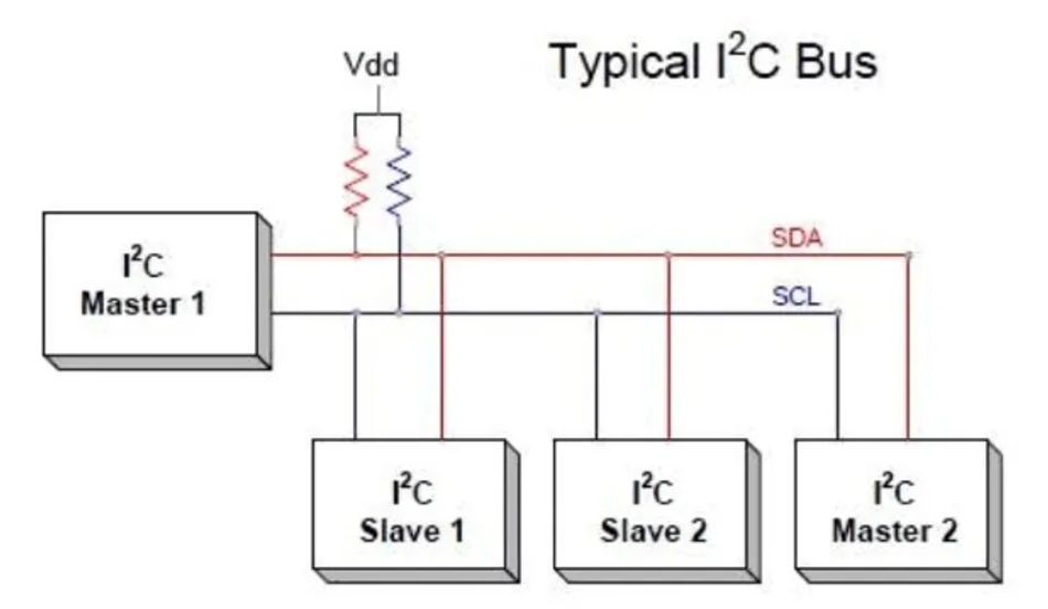
I2C, or Inter-Integrated Circuit, is a serial communication protocol designed for short-distance, low-speed communication between devices on a single bus. Operating on a master-slave configuration, it uses two lines—a clock line (SCL) and a data line (SDA)—to transmit and receive data. The master device initiates communication and controls the clock signal, while slave devices respond as addressed. Both lines are open-drain, meaning devices can pull the line low (0 volts) to indicate a logical '0' or let it float high (up to a specified voltage, typically 3.3V or 5V) for a logical '1'. Pull-up resistors are necessary to ensure the lines return to the high state when no device actively pulls them low.
How I2C Protocol Works
Start Condition
Master pulls the SDA line low while SCL is high.
Signals the beginning of an I2C transaction to all devices on the bus.
Slave Addressing:
The master transmits the 7 or 10-bit address of the target slave device.
Includes a read/write bit (0 for write, 1 for read).
Slave Acknowledgment
The addressed slave pulls the SDA line low during the next clock pulse to acknowledge its address.
Data Transfer
The master transmits or receives data byte-by-byte.
Each byte is followed by an acknowledgment bit from the slave.
Stop Condition
Master releases the SDA line high while SCL is high.
Signals the end of the I2C transaction.
The protocol supports different speed modes to accommodate various application requirements. Standard I2C devices typically support data rates up to 100K bits per second. Fast-mode devices extend this to 400K bits per second, while high-speed devices can achieve data rates of up to 3.4Mbits per second. These different speed modes enable I2C to cater to a wide range of devices, from slower, low-power components to faster, more complex devices.
I2C is widely used in applications involving sensors, EEPROMs, and other peripherals where simplicity and low power consumption are essential. Its multi-device capability allows numerous devices to share the same bus, making it ideal for systems with multiple sensors or low-speed peripheral modules.
Further Reading: I2C vs SPI: A Comprehensive Comparison and Analysis
SPI (Serial Peripheral Interface)
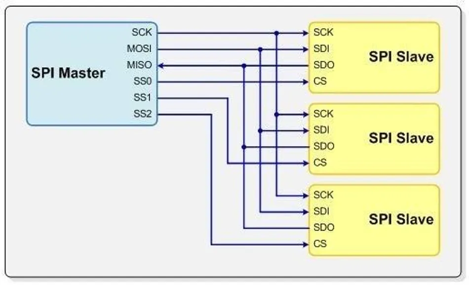
SPI, or Serial Peripheral Interface, is a high-speed communication protocol that uses separate data lines for full-duplex data transmission. This allows simultaneous sending and receiving of data, making it ideal for applications requiring rapid and efficient data exchange. The protocol employs four key lines:
A clock line (SCLK)
Two data lines (MOSI for Master Out Slave In, and MISO for Master In Slave Out),
hip select line (CS) to enable communication with specific slave devices.
SPI supports continuous data streams, enabling the transmission or reception of an arbitrary number of bits without the need for frequent start/stop conditions. It’s a key advantage over other protocols like UART and I2C which transmit data in packets.
SPI is particularly well-suited for use cases such as SD cards and flash memory, where high-speed data transfers are critical. Its straightforward design and ability to handle multiple slaves via dedicated chip select lines make it a popular choice for high-performance embedded systems.
How SPI Communication Works
Device Selection:
The master device asserts the Slave Select (SS) line to select the specific slave device it wants to communicate with.
Clock Signal Generation:
The master device generates a continuous clock signal (SCK) to synchronize data transfer.
Data Transmission:
Master to Slave: The master transmits data serially bit-by-bit on the Master Out Slave In (MOSI) line.
Slave to Master: Simultaneously, the slave transmits data serially bit-by-bit on the Master In Slave Out (MISO) line.
Data Reception:
Both master and slave receive data on their respective input lines (MISO and MOSI) synchronized with the clock signal.
Data Transfer Completion:
After transmitting the required number of bits, the master de-asserts the Slave Select (SS) line to deselect the slave device.
Communication End:
Data transmission ceases, and the master can initiate communication with another slave device or perform other operations.
Further Reading: SPI Protocol: Revolutionizing Data Communication in Embedded Systems
UART (Universal Asynchronous Receiver-Transmitter)
UART, or Universal Asynchronous Receiver-Transmitter, is a simple and widely used communication protocol that operates asynchronously. It achieves data transmission by using start and stop bits to mark the beginning and end of each data packet, ensuring proper synchronization without requiring a shared clock line.
The protocol converts data bytes into a sequential stream of bits for transmission and vice versa for received data. Unlike synchronous protocols, UART does not require a shared clock signal for data synchronization. This makes UART ideal for systems where simplicity and low hardware overhead are priorities.
How UART Works
Data Preparation
The transmitting device prepares the data to be sent, converting it into a serial stream of bits.
Start Bit Transmission
A start bit (typically a logic low signal) is transmitted to signal the beginning of the data frame.
Data Bit Transmission
The data bits are transmitted serially, one bit at a time, typically from the least significant bit (LSB) to the most significant bit (MSB).
Parity Bit Transmission (Optional)
If parity checking is enabled, a parity bit is transmitted to ensure data integrity.
Stop Bit Transmission
One or more stop bits (typically a logic high signal) are transmitted to indicate the end of the data frame.
Idle State
After the stop bit, the communication line returns to an idle state (typically a logic high signal).
Reception
The receiving device detects the start bit, samples the incoming data bits at the agreed-upon baud rate, and reconstructs the original data.
Data Processing
The received data is then processed by the receiving device.
One of UART’s common applications is in serial communication with peripherals like GPS modules, where reliable and straightforward data exchange is essential. Its compatibility across a variety of devices further enhances its versatility, making it a go-to protocol in embedded systems where ease of implementation and interoperability are key considerations.
Suggested Reading: UART vs SPI: A Comprehensive Comparison for Embedded Systems
Key Differences and Comparative Analysis
Speed and Performance
SPI excels at high-speed data transfer due to its synchronous nature. With clock frequencies reaching 10 MHz and 8-bit transfers, it achieves data rates of 10 Mbps, enabling rapid data exchange between devices.
I2C offers flexibility with various speed modes: standard (100 kbps), fast (400 kbps), and high-speed (3.4 Mbps). While high-speed mode provides significant speed, it may not always match the throughput of SPI. The choice of speed mode depends on the application's specific requirements.
UART, while simple to implement, has inherent speed limitations. Typical maximum baud rates around 115200 bps may be insufficient for demanding applications like real-time systems or high-speed data logging. In such cases, higher-speed protocols like SPI or Ethernet are often more suitable.
Hardware Complexity
I2C requires pull-up resistors on the clock (SCL) and data (SDA) lines to ensure signal stability, which adds slight complexity to its hardware design. Each device connects to the shared bus with unique addresses, reducing the need for additional lines but requiring careful management of bus contention.
SPI, by contrast, demands multiple chip select (CS) lines for each slave device, increasing the pin count as the number of devices grows. It utilizes dedicated lines for data (MOSI and MISO) and a clock signal (SCLK), resulting in a straightforward but hardware-intensive implementation for systems with numerous peripherals.
UART’s hardware design is simpler, using only two lines—transmit (TX) and receive (RX)—with no need for a clock signal. This makes UART highly compatible and easy to implement, especially in systems with low-speed requirements.
Addressing Schemes
SPI doesn’t use dedicated address lines. Instead, it relies on individual Slave Select (SS) or Chip Select (CS) lines to identify the target device. This approach simplifies the protocol and contributes to its high-speed data transfer capabilities by eliminating the overhead of transmitting address bytes. However, this also limits the number of devices that can be connected to an SPI bus to the number of available SS lines.
I2C incorporates a built-in addressing scheme. Each I2C device possesses a unique 7 or 10-bit address, enabling direct communication between the master and the intended slave without the need for additional selection lines. This addressing mechanism supports up to 128 (7-bit) or 1024 (10-bit) devices on a single bus.
UART lacks inherent addressing capabilities. Consequently, all devices on a UART bus receive the transmitted data indiscriminately. Hence, it requires additional mechanisms, such as software-based addressing or the use of separate communication channels, to ensure that data is received only by the intended recipient.
Distance Communication
SPI is highly efficient for short-distance communication within embedded systems. However, as the communication distance increases, factors like signal degradation, electromagnetic interference, and timing issues become more pronounced. This makes SPI less suitable for long-range applications. For longer distances, protocols like RS-485 or CAN, specifically designed for robustness and long-distance communication, are often preferred.
Suggested Reading: Industrial Communication Protection for RS-485 and Ethernet
I2C is primarily intended for short-distance communication within a single circuit board or between closely located components. It also encounters limitations over longer distances. The capacitance of the bus and the resistance of the pull-up resistors increase with distance, leading to slower signal rise times and potential signal degradation. While I2C supports various speed modes, its effectiveness diminishes significantly over longer distances. In such scenarios, UART or SPI might be more suitable.
UART is well-suited for short-distance communication, such as connecting a microcontroller to a nearby sensor or a computer to a peripheral device. However, over longer distances, signal degradation, and noise interference can significantly impact data reliability. Additionally, UART's relatively lower data rates compared to protocols like SPI may limit its suitability for high-speed applications.
Use Cases and Scalability
I2C, SPI, and UART each possess unique characteristics that make them suitable for different applications.
I2C is ideal for systems with multiple sensors or low-speed peripherals. It finds common use in applications such as temperature sensors, real-time clocks, and EEPROMs. However, its scalability is limited by speed degradation as more devices are added to the shared bus.
SPI excels in high-speed data transfer requirements and is frequently employed in flash memory, SD card interfaces, and digital displays. Its scalability can be challenging due to the increased pin requirements for additional slave devices.
UART is best suited for point-to-point communication with low-speed peripherals. It has applications in GPS modules, RFID readers, and Bluetooth modules. However, its scalability is limited by its inherent design, which is primarily intended for two-device communication.
Power Efficiency
SPI with its high clock speeds and full-duplex communication, generally exhibits higher power consumption. The high-frequency clock signals contribute significantly to dynamic power consumption. Moreover, multiple communication lines (MOSI, MISO, SCK, and SS) also increase power consumption. While SPI may not always require pull-up resistors, its overall power consumption can be higher compared to other protocols.
I2C typically consumes less power than SPI due to its slower data rates and reduced number of communication lines (SDA and SCL). However, the presence of pull-up resistors on the data and clock lines can contribute to power consumption. The power consumption of I2C can vary depending on factors such as the values of the pull-up resistors and the bus capacitance.
UART often demonstrates lower power consumption compared to SPI and I2C. Its slower data rates minimize dynamic power consumption, resulting in lower overall power usage. However, in idle mode, UART may consume more power due to the maintenance of a logical 'high' state on the transmission line. Many UART implementations incorporate power-saving modes, such as sleep mode, to significantly reduce power consumption during periods of inactivity.
Comparison in a Nutshell
The following table demonstrates the key differences between SPI, I2C, and UART:
Feature | SPI | I2C | UART |
Addressing | Slave Select (SS) lines | Unique 7/10-bit addresses | No inherent addressing |
Speed | Highest speed among the three | Medium speed | Lower speed |
Complexity | Simpler addressing, higher complexity in managing multiple devices | Moderate complexity | Simplest protocol |
Data Rate | Up to 10 Mbps (or higher) | Up to 3.4 Mbps (high-speed mode) | Up to 115200 bps (typical) |
Number of Devices | Limited by number of SS lines | Up to 128 (7-bit) or 1024 (10-bit) | Limited by software or external mechanisms |
Bus Contention | Potential for contention if multiple devices are selected simultaneously | Less prone to contention | Susceptible to data collisions if not properly managed |
Power Consumption | High power consumption due to multiple lines and high-frequency clocks | Moderate consumption due to the inclusion of pull-up resistors and clock lines | Low power consumption due to no clock lines and pull-up resistors |
Applications | High-speed peripherals (e.g., flash memory, SD cards, ADCs), LCD displays, digital sensors | Sensors (temperature, humidity, etc.), EEPROMs, Real-time clocks, Low-speed peripherals | GPS modules, RFID readers, Bluetooth modules, Serial consoles, Debugging interfaces |
Challenges and Limitations
Addressing Protocol-Specific Limitations
Each protocol has its own set of limitations, which engineers must consider when designing embedded systems. These trade-offs often involve balancing factors such as hardware complexity, speed, power efficiency, and ease of implementation, depending on the application requirements:
I2C:
Limitation: Susceptible to noise due to its reliance on pull-up resistors and shared bus.
Solution: Use shielded cables and proper grounding to minimize interference; limit the bus length to reduce signal degradation.
Clock Stretching: Some slower devices may require extra time to process data or generate acknowledgment. If a device stretches the clock line (keeps it low) for an extended period, it can disrupt communication with other devices on the bus.
Solution: Implement appropriate clock stretching mechanisms in the master device to accommodate slower devices. Ensure that the master device can detect and handle clock stretching conditions gracefully.
SPI:
Bus Contention: When multiple slave devices are selected simultaneously by asserting their respective Slave Select (SS) lines, it leads to "bus contention." This situation can cause unpredictable behavior, data corruption, and even damage to the devices.
Solution: Careful design and implementation of slave selection logic are crucial. Ensure that only one slave device is selected at a time. Employ techniques like daisy-chaining or using a multiplexer to select devices sequentially.
Multiple Lines: Requires additional pins for chip select lines, which increases hardware complexity in multi-slave configurations.
Solution: Employ SPI expanders or daisy-chaining techniques to reduce pin count and simplify hardware.
Signal Integrity: High-speed SPI communication can be susceptible to signal integrity problems, including signal reflections, crosstalk, and electromagnetic interference (EMI). These issues can distort the signal, leading to data errors.
Solution: Use proper grounding techniques to minimize noise. Employ differential signaling techniques to improve signal quality.
UART:
Clock Drift: Slight variations in the clock frequencies of the transmitter and receiver can lead to timing mismatches, causing the receiver to sample data bits at incorrect times. This can result in bit errors.
Solution: Use high-quality crystal oscillators or external clock sources to minimize clock drift between the transmitter and receiver.
Noise Interference: External noise sources can corrupt the UART signal, leading to bit errors and synchronization loss.
Solution: Ensure proper grounding techniques to minimize the impact of noise and ground loops.
Baud Rate Mismatch: If the transmitter and receiver are configured with different baud rates, the receiver will sample data at the wrong intervals, resulting in incorrect data interpretation.
Solution: Using 1.5 or 2 stop bits can provide more time for the receiver to resynchronize in case of minor timing errors. Also, use error detection mechanisms such as parity checks or checksums to detect and potentially correct errors caused by synchronization issues.
Troubleshooting Common Issues
To address common communication issues in I2C, SPI, and UART, follow these troubleshooting steps:
I2C Clock Stretching:
Verify that all slave devices support clock stretching.
Check for mismatched pull-up resistor values and adjust them to ensure proper signal levels.
Use an oscilloscope to detect if the clock line (SCL) is being held low by a slave device.
Misconfigured SPI Modes:
Confirm that both master and slave devices are set to the same clock polarity (CPOL) and phase (CPHA).
Test individual connections (MOSI, MISO, SCLK, CS) for continuity and correct wiring.
Ensure the clock frequency is within the acceptable range for the slave device.
Incorrect Baud Rates in UART:
Match the baud rate settings on both transmitting and receiving devices.
Inspect the TX and RX connections for proper orientation.
Use a logic analyzer to check for corrupted or incomplete data frames.
Conclusion
I2C, SPI, and UART each offer distinct advantages suited to specific applications. I2C excels in simplicity and multi-device support, making it ideal for systems with numerous sensors or low-speed peripherals. SPI stands out for its high-speed data transfer capabilities, providing efficient communication for storage devices and digital displays. UART, with its minimal hardware requirements, is a reliable choice for straightforward point-to-point communication with peripherals like GPS modules.
The context of the application is critical when choosing a protocol. Factors such as environmental conditions, resource constraints, and the complexity of the system can significantly influence which protocol is most suitable. Engineers must weigh factors such as speed, scalability, hardware complexity, and power efficiency to select the most appropriate option for their specific project requirements.
Frequently Asked Questions (FAQs)
When should I use I2C instead of SPI?
I2C is advantageous when multiple devices need to share the same communication bus, as it allows for simple wiring and device addressing. Its low power consumption and ease of implementation make it ideal for applications like sensor networks and low-speed peripherals.
Why is SPI faster than UART and I2C?
SPI achieves higher speeds due to its full-duplex communication, where data can be transmitted and received simultaneously. Additionally, the dedicated clock line ensures precise timing, enabling rapid and efficient data transfer.
Can I use UART for multi-device communication?
UART is inherently designed for point-to-point communication and does not natively support multi-device setups. However, multiplexers or software-based solutions can be implemented to enable communication with multiple devices, though these methods increase system complexity.
What are the power requirements for these protocols?
I2C: Operates at low power levels, suitable for battery-powered devices.
SPI: Consumes more power due to its continuous clock signal and high-speed operation.
UART: Generally low power consumption, with variations based on baud rate and data activity.
References
An introduction to I2C and SPI protocols | IEEE Journals & Magazine | IEEE Xplore
A New Approach to Improve Reliability in UART Using Checksum Algorithm | SpringerLink
Universal Asynchronous Receiver Transmitter (UART) Protocol - GeeksforGeeks
in this article
1. Introduction2. Protocol Basics: What Makes I2C, SPI, and UART Unique?3. Key Differences and Comparative Analysis4. Challenges and Limitations5. Conclusion6. Frequently Asked Questions (FAQs)7. ReferencesNo time now? Save for later.
We only use your email to send this link. Privacy Policy.