Protolabs Insight: Mastering Complex Machined Parts
In this video we look at complex machined parts, focusing on the five key things you need to keep in mind when creating a particularly complex part: hole placement, grooves, threading, milled text, and corners.
11 Sep, 2023. 4 minutes read
The Protolabs Insight video series will help you master digital manufacturing, covering cover specific topics such as choosing the right 3D printing material, optimising your design for CNC machining, surface finishes for moulded parts, and much more.
Transcript
Hello and welcome to this week’s Insight.
This time around we’re going to be having a chat about complex machined parts, which are becoming more and more common as our CNC machine tools gain greater capabilities.
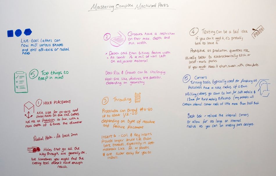
Live-tool lathes can now mill various shapes and drill off-axis or radial holes, operations that would once have required a separate trip to the milling department, while machining centres are equipped with indexing heads that scan complete multiple sides of the part in a single operation.
However, this doesn’t mean that just anything goes. Certain machining rules still apply, and not following them can lead to some incredibly expensive reworks and project delays. Over the next few minutes we’re going to have a quick run through five of the top things you need to keep in mind when you’re eyeing up a particularly complex part.
First up, we have hole placement. You need to keep this in mind because the ideal depth and size of the holes we can put into a part shift a bit depending on where it’s located.
For example, the minimum size for on-axis and axial holes on the CNC lathes we use at Protolabs is 1mm, with a maximum depth of six times the diameter. Any narrower or deeper than that, and we start running into problems.
Meanwhile, radial holes – which is to say those drilled from the side of the part – should be at least two mil in diameter.
Now, holes that go all the way through turned or milled parts are usually okay, especially if they’re hollow or tube-shaped, but sometimes you might find that the cutting tool doesn’t have enough reach. If you’re including a part with a hole like that, make sure to chat with your machinists first to clear up any issues.
Next, we have particularly deep features. Grooves have a restriction on their maximum depth and minimum width, while all other slot-like milled features generally read from the same playbook as drilled holes in terms of size. Again, a good rule of thumb is to keep the depth less than six times the feature width. Oh, and be sure to leave at least half a mil of wall left on the adjacent material.
Unfortunately, deep ribs and grooves can be pretty challenging to work with regardless of their placement. It is possible to cut heat sink-like features on a turned or milled part, but this depends on the actual part geometry and available tools. Again – and you’ve heard this one before – have a chat with your supplier to clear up any issues.
The next thing on our list for today is threading. Designers frequently add threaded features to milled and turned parts, and there are a whole load of options for these, so, yet again, speak to your supplier.
For example, at Protolabs we can thread from #4-40 up to about 1/2-20 depending on the type of machine and the feature placement.
Having said all that, you might also think about using an insert. Coil and key inserts provide longer service life than bare threads, especially in soft materials like aluminium or plastic, and are super easy for you to install. It won’t always be the right answer, but it can be the most convenient and cost-effective one.
Right, three down, two to go.
And for number four, we have a piece of advice that plenty of us have probably heard already – texting can often be a bad idea.
No, we don’t mean on your phones – not this time, anyway. What we mean is having text milled into your parts.
This is a requirement in some sectors, like aerospace and medical work where parts need numbers and names permanently marked, but if you don’t really need to include it, our advice would be that you probably shouldn’t bother. Recessed text may look nice, but it’s also one of the more time-consuming of all machining operations, and is downright prohibitive as production quantities rise.
It’s usually better to electrochemically etch or laser-mark parts, but if you really must have engraved text, keep it short and sweet with simple, clean fonts. That makes it much easier to mill.
Finally, coming in at number five is a quick warning about your corners. If they’re too sharp, they can be a real nightmare to machine.
For example, the turning tools typically used for finishing here at Protolabs have a 0.8mm nose radius, so any mating parts should be designed with this in mind. Milling cutters go down to 1mm for soft metals and 1.2mm for hard metals and plastics, which means any pockets will contain internal corner radii a little more than half that.
Now, that’s pretty sharp, but remember that milling with a tool that small takes a real long time and your still left with the pockets. Your best bet is to relieve the internal corners or allow for as large an internal radius as you can on mating part designs.
Right, that’s our five tips. Hopefully that helped out a little and given you something to think about over the weekend!
Watch other Protolabs Insight videos here.