Microbial Fuel Cell: How It Works, What It Delivers, and Whe
A microbial fuel cell turns the metabolism of living bacteria into an electrical current. This guide covers the electrochemistry, microbiology, materials, real performance numbers from pilot plants, and the economics that still keep the technology out of mainstream power generation.

21 Sep, 2026. 13 minutes read
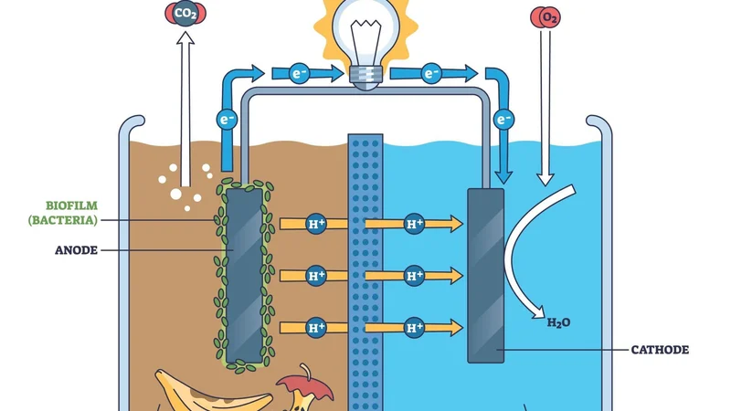
Illustration of a microbial fuel cell
Key Takeaways
A microbial fuel cell (MFC) uses bacteria as the catalyst at the anode, oxidizing organic matter and routing the released electrons through an external electrical circuit to a cathode where oxygen is usually reduced to water.
Theoretical cell voltage is about 1.1 V with oxygen as the final electron acceptor, but overpotentials and internal resistance mean practical cells deliver a fraction of that.
The largest pilot to date, a 1000 L modularized system, recovered 0.033 kWh per cubic meter of municipal wastewater while removing 70 to 90 percent of chemical oxygen demand.
Benthic cells have powered oceanographic sensors and acoustic modems on the seafloor for about six months at a time.
The cathode material occupies 75 percent of total cell cost and is expected to pay back in more than 8 years.
Introduction
A microbial fuel cell is a bioelectrochemical reactor that converts chemical energy in organic matter directly into electricity. It uses microorganisms instead of precious metal catalysts to drive the anode reaction. One widely cited review defines MFCs as devices able to transform chemical to electrical energy via electrochemical reactions involving biochemical pathways.[1]
The definition hides an engineering problem. You are asking a living biofilm to act as an electrode catalyst, at ambient temperature, in a dilute and variable electrolyte, and to keep doing it for years. Everything that makes an MFC attractive- meaning no external fuel, no heating, and a self-replicating catalyst also caps how much power you can pull out of it.
This article discusses the electrochemistry, the types of bacteria, electron movement, architecture, and materials that set performance in microbial fuel cells. We will also look at what pilot-scale systems actually delivered, and where the technology earns its place today.
How a Microbial Fuel Cell Works
An MFC has three critical components. An MFC has three critical components[2]:
Anode
Cathode
Proton Exchange Membrane (PEM) that separates the two chambers
Oxidation at Anode Without Oxygen
The anode chamber is kept anaerobic. Bacteria colonize the anode surface as a biofilm and oxidize the organic substrate, releasing electrons, protons, and carbon dioxide as an oxidation byproduct.[2]
Keeping oxygen out is critical because continuous current production is only feasible when the microbes are separated from oxygen or any other electron acceptor besides the anode, which is precisely why the anode chamber is made anaerobic.[2]
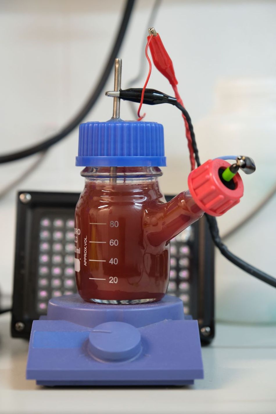
Substrates span a wide range, from glucose, acetate, and carbohydrates to cellulose, molasses, and the organic matter in wastewater and agricultural residues.[1] That tolerance for messy, dilute organic waste is the technology's core advantage over conventional low-temperature fuel cells, which need clean fuel.
Lossy Cathode
Electrons travel through the external electrical circuit and any load, and arrive at the cathode. Protons (Hydrogen ions) migrate separately through the separator to the cathode chamber. Here, they recombine with electrons and an oxidant.
Oxygen "has primarily been used as the oxidant due to its abundance and high reduction potential".[1] Two reduction pathways compete. A four-electron route takes oxygen straight to water, while a two-electron route stops at hydrogen peroxide.
The four-electron route is preferred because it transfers twice the amount of electrons per unit of oxygen.[1] Platinum catalysts favor the four-electron route; activated carbon tends toward the two-electron route, producing hydrogen peroxide at yields reported around 50 to 70 percent.[1]
It’s important to note that oxygen reduction is sluggish. According to reviews of electron acceptors, the cathode bottleneck arises due to poor contact of oxygen with the electrode and the slow rate of reduction.[3]
On the other hand, laboratory cells substitute ferricyanide, which produced 50-80% higher power than oxygen with a carbon electrode, but it’s specific to basic laboratory studies because it must be chemically regenerated.[3] Ferricyanide power densities will not carry over to air-breathing field units.
Suggested Reading: Cathode Anode: The Basics and Applications
Proton Exchange Membrane or Salt Bridge
Protons reach the cathode chamber by penetrating through the PEM or a salt bridge.[2] Those two options sit at opposite ends of the cost and performance range.
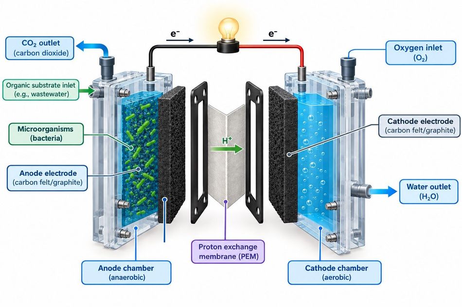
A PEM, typically a cation exchange membrane such as Nafion, is the standard choice. Alternatives that have been used include j-cloth, nylon fibers, glass fibers, ceramics, and membrane-less MFCs have been described as well.[1]
A salt bridge is the cheapest option and common in bench builds, but its long, narrow ion path adds the resistance that limits MFC power. It is a teaching device, not a production choice.
Separator | Typical use | Cost position | Main drawback |
Cation exchange membrane (Nafion-type PEM) | Laboratory and pilot reactors | High | Membrane and cathode dominate reactor cost [4] |
Low-cost separators (j-cloth, nylon, glass fiber, ceramic) | Cost-reduced pilots | Low to moderate | Oxygen crossover into the anode chamber |
Salt bridge | Bench and educational cells | Lowest | Long ion path adds ohmic loss |
No separator (membrane-less) | Single-chamber air-cathode designs [1] | Lowest | Oxygen diffusion to the anode, lower coulombic efficiency |
Suggested Reading: What Is a Fuel Cell? Theory, Components, Types, and Applications
Current Generating Bacteria
The bacteria that make this work are called exoelectrogens. Instead of ending respiration at a soluble acceptor inside the cell, they push electrons from their electron transport chain onto an insoluble external surface. Examples bacteria types include[1]:
Geobacter sulfurreducens
Rhodoferax ferrireducens
Shewanella oneidensis
Pseudomonas alcaliphila
Pseudomonas aeruginosa
Reported single-species performance varies widely. One 2024 analysis lists 2.5 W/m² and Pseudomonas aeruginosa at 2.2 W/m².[5]
Direct Electron Transfer
Direct transfer needs direct contact between the anode surface and the outer membrane of the bacteria. This transfer must be mediated by cytochrome c proteins, conductive pili, or bacterial nanowires, which are basically extracellular conductive connections.[1]
The nanowire story has become specific. In Geobacter sulfurreducens, filaments built from the cytochrome OmcZ can offer 1000 times higher conductivity than preparations primarily consisting of OmcS.
OmcZ is the only cytochrome out of over 80 multiheme proteins in the Geobacter sulfurreducens genome necessary for long-distance conductivity in electrode-associated biofilms. The OmcZ gene is found to be a 400-800% more conductive electrode biofilm. Importantly, these filaments are about 50 Å across and carry eight heme groups per subunit.[6]
In Shewanella oneidensis MR-1, the route is a defined protein chain. CymA acts as the predominant quinol oxidase for EET via Mtr, and the outer-membrane complex formed by MtrCAB and OmcA handles reduction of extracellular electron acceptors.[7]
Mediated Electron Transfer
Where a mediator is involved, a soluble redox shuttle ferries electrons from the cell to the electrode. Shewanella secretes electron-shuttle compounds like flavin mononucleotide (FMN) and riboflavin (RF). These are either synthesized and secreted by MR-1 or added exogenously, and play a critical role in efficiently transferring electrons from OM c-Cyts to external solid EAs.[7]
The size of that mediator effect is worth noting for anyone designing a cell. In one study, wild-type MR-1 produced a maximum power density of 120.5 mW/m². An engineered strain reached 436.5 mW/m², and the same strain with exogenous riboflavin added reached 702.3 mW/m².[7] Mediator availability, not just biomass, sets the ceiling.
Voltage, Power Density, and Coulombic Efficiency
Low Voltage Generation
The theoretical cell voltage is about 1.1 V, based on the theoretical anode and cathode potentials and assuming oxygen as the final electron acceptor.[8] You will never measure that on a working cell.
Operating voltage follows the relation that cell voltage equals the thermodynamic voltage minus the anode overpotential, minus the cathode overpotential, minus the product of current and internal resistance.[9]
Internal resistance can be split into partial internal resistances covering the anode, the cathode, and ion transport.[8] In a flat-plate plant-MFC study, the anodic term was the largest single contributor, and total internal resistance ranged from 1.3 to 9.7 Ω·m² of membrane area depending on depth.[8]
The practical consequence shows up in field hardware. In the MARS seafloor deployment, the engineers state plainly that the energy harvested from any benthic cell will be at low voltage, below 0.8 V, and therefore impractical to power most solid-state devices.[10]
Coulombic Efficiency
Coulombic efficiency is the fraction of electrons available in the substrate that actually reach the anode, calculated as recovered coulombs over theoretical coulombs.[9] It is the number that tells you how much of your organic waste went into current rather than into competing processes such as methanogenesis or aerobic respiration on leaked oxygen.
Reported values depend heavily on substrate and community. Geobacter species show a coulombic efficiency of about 100 percent on acetate and 83 percent on glucose, while wastewater-fed systems have been reported between 65 and 89 percent.[9]
Improving the biofilm itself moves the number a long way: one biofilm transplanting approach raised power from 0.6 W/m² to 4.3 W/m² and coulombic efficiency from 4 to 81 percent.[1]
Electrode Materials and Design Choices
Carbon dominates anode construction. It is the most commonly applied anode material for MFCs due to its superior biocompatibility, excellent chemical and thermal stability, high conductivity, high mechanical strength, and low cost. Moreover, Carbon-based electrodes are divided into flat, packed, and brush structures.[2]
The anode material controls how well bacteria adhere and form the stable biofilm that efficient electron transfer requires. Increasing surface roughness improves adherence and allows higher power density, but it also increases fouling, which is a long-term operability problem rather than a start-up one.[2]
Material | Reported behavior | Engineering note |
Graphite rod | More efficient when the surface is roughened, but too costly for large-scale use [2] | Easy to connect, hard to increase area |
Graphite foam | Higher power density and cell biomass than rod and felt in a comparative study [2] | Open porosity favors biofilm access |
Carbon cloth | Ammonia gas pretreatment gave 1,970 mW/m² at 60% coulombic efficiency [5] | Surface chemistry is a cheap performance lever |
Carbon mesh | Favorable on cost versus sheets or cloths, with larger power density [2] | Practical candidate for scale-up |
Carbon fiber brush | Used as 4 m anodes in seafloor cells [10] | Very high area per unit volume |
On the cathode side, platinum delivers the four-electron oxygen reduction pathway, but it’s unsustainable, whereas carbonaceous materials are viable for low-cost practical applications, lowering the capital costs.[1]
Platinum-group-metal-free M-N-C catalysts have reached 1.5 to 2.5 W/m².[1] For biosensing duty, β-MnO₂ has substituted for platinum in a cell that ran for more than one and a half years while maintaining a linear BOD response.[4]
Moreover, the operating conditions require temperature ranging between 15 °C and 45 °C with close to ambient as the optimum, at near-neutral pH.[1][2]
What Pilot Plants Actually Delivered
Pilot MFCs span roughly 6 L to 1500 L in reactor volume.[11] The most informative single data point is the largest.
A 1000 L modularized MFC built from 50 modules was operated in two municipal wastewater treatment plants for more than one year, under two different water flow connections, and tested on wastewater with both low (average 80 mg/L) and high (average 250 mg/L) initial COD.[12] Results were split:
Treatment worked. Effluent COD stayed below 50 mg/L with a removal rate of 70 to 90 percent.[12]
Power was modest. Maximum power density reached 125 W/m³ on artificial wastewater but only 7 to 60 W/m³ on real municipal wastewater.[12]
Energy recovery was small. The system recovered 0.033 ± 0.005 kWh per cubic meter of municipal wastewater at a hydraulic retention time of 2 hours.[12]
That third figure is the honest summary of where MFC power generation stands. A construction review states that the major barrier to industrial implementation is the technology's inability to produce energy at a sufficient rate that satisfies a significant fraction of the energy requirements of a large-scale wastewater treatment facility.[2]
Applications Suitable for MFCs
Wastewater Treatment and Bioremediation
Conventional wastewater treatment is expensive and energy intensive.[2] MFCs are attractive there less as generators than as low-energy treatment. They are preferable to some advanced treatment technologies because of their lower energy requirement and reduced chemical usage. Also, they can remove persistent organic pollutants and heavy metals, making them suitable for bioremediation.[2]
Suggested Reading: Dirty water boosts prospects for clean hydrogen
Remote and Marine Sensor Power
This is the application with the strongest field record. Benthic microbial fuel cells are bioelectrochemical devices that run on the potential difference between anoxic sediment and oxic seawater.[10]
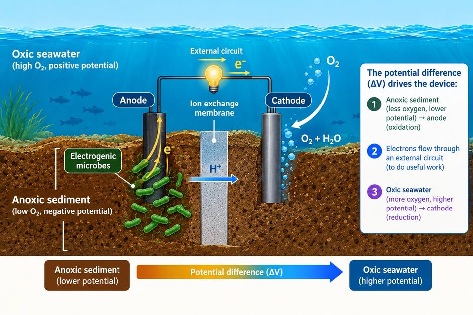
In a deployment at the Monterey Accelerated Research System observatory, two benthic cells sited about 0.5 km from the cabled node at roughly 890 m depth powered acoustic modems and oceanographic sensors.[10]
At peak, they produced continuous power densities of about 35 mW/m² of footprint area, against a typical range of 1 to 10 mW/m² continuous and 10 to 30 mW/m² peak for benthic cells generally.[10] Under unusual conditions such as a methane cold seep or hydrothermal vent, peak power densities of 380 to 500 mW/m² have been observed.[10]
Each chamber was PVC, 0.36 m high and 0.57 m in diameter, with a 0.259 m² footprint. Anodes were 4 m carbon fiber brushes and cathodes 2.2 m, sized on the finding that a cathode can be at least 0.5 times the anode length before the cathode reaction becomes rate-limiting.[10]
A power management platform combining a multistage boost converter, a 2 V supercapacitor, and a microcontroller charged two 3.7 V lithium-ion cells in series to supply 5 V to the sensor and 7 V to the modem. Sensors returned data reliably across an operational life of about six months, with the systems left in place for more than twelve.[10]
Biosensing and Water Quality Monitoring
Biochemical oxygen demand is one of the most widely used water quality parameters, and the standard BOD5 test measures oxygen consumed by microorganisms after five days of incubation at 20 °C.[4]
In an MFC biosensor, the developed biofilm in the anodic chamber is a bioreceptor, while the anode acts as a transducer.[4]
Reported performance is genuinely useful:
Response time fell from 2.1 h to 1.4 h simply by lowering external resistance from 100 Ω to 10 Ω, and shrinking the anode chamber from 25 mL to 5 mL cut it from 36 minutes to 5 minutes.[4]
Detection reached a lower limit of quantification of 0.34 mg/L BOD in one configuration.[4]
A membrane-less cell with an applied voltage and retention time raised from 5 h to 20 h lifted the upper limit of the linear range from 320 to 1280 mg/L.[4]
One MFC biosensor operated stably for over five years, compared with 7 to 140 days for earlier BOD biosensors.[4]
Sensitivity to operating conditions is the flip side and must be compensated. Current density rose by 6 mA/m² for every 1 °C between 11 °C and 33 °C, and peaked at 288 mA/m² at pH 7.0 versus 186 mA/m² at pH 6.0 and 184 mA/m² at pH 8.0.[4]
Suggested Reading: Mass producing wearable biosensors
Microbial Electrolysis Cells
Invert the device and you get a microbial electrolysis cell. Rather than harvesting current, you add a small voltage and collect hydrogen at the cathode. The minimum applied voltage is about 0.2 V to break the thermodynamic barrier, with a practical range of 0.2 to 0.8 V. That compares with 1.8 to 2 V for conventional water electrolysis.[13]
Reported substrate-to-hydrogen conversion efficiency runs 80 to 100 percent, against about 65 percent for water electrolysis and about 33 percent for dark fermentation.[13]
Suggested Reading: Making hydrogen fuel cells 'less precious'
Economics and Common Failure Modes
Cost, not biology, is the binding constraint. A techno-economic review reports a capital cost of approximately USD 10,000 for a double-chamber system processing 54 m³ of wastewater per day. The review states that the cost of the cathode is roughly a maximum of 75% of the total cost of an MFC.[14]
Moreover, the modeled discounted payback period was 8.25 years.[14] Membrane and cathode together account for the majority of reactor investment.[4]
Recurring barriers named across reviews are mass transfer limitation, pH control, scaling up electrode materials, and cost itself.[14] A separate analysis names cost, scalability, and environmental sensitivity as the primary challenges.[5] Construction reviews add low power output, slow start-up, and lower efficiency than competing technologies.[2]
Practical mistakes worth avoiding:
Comparing power densities normalized to different areas. Anode area, cathode area, membrane area, and footprint all appear in the literature.[9]
Quoting ferricyanide-cathode results as achievable. They are not, in an air-breathing cell.[3]
Letting oxygen into the anode chamber. Continuous current production depends on keeping the microbes away from every electron acceptor except the anode.[2]
Specifying platinum by default. Its cost is described as prohibitive at scale, and carbon or PGM-free catalysts are the practical route.[1]
Designing without power conditioning. Harvested energy at these voltages is impractical for powering most solid-state devices directly.[10]
Conclusion
A microbial fuel cell is a working piece of biotechnology, but it is not a power plant. The electrochemistry caps you near 1.1 V in theory and delivers a fraction of that in the field; the microbiology is now understood down to named cytochromes and nanowire proteins, and the materials question has largely resolved toward carbon.
What the pilot record shows is a treatment technology with a useful electrical side effect, not the reverse. Where MFCs win outright is where grid power is absent, and demand is tiny: seafloor sensors, remote monitoring, and self-powered biosensors that replace a five-day laboratory test with a real-time signal. Those are real deployments with real numbers behind them, and they are where an engineer evaluating this technology should start.
Frequently Asked Questions
1. What is a microbial fuel cell?
It is a device that converts chemical energy in organic matter into electrical energy using microorganisms as the catalyst, described in the literature as transforming chemical to electrical energy through electrochemical reactions involving biochemical pathways.
2. How does a microbial fuel cell work?
Bacteria in an anaerobic anode chamber oxidize organic matter, releasing electrons and protons and producing carbon dioxide. Electrons travel through an external electrical circuit to the cathode while protons cross a PEM or salt bridge, and at the cathode they combine with an oxidant, usually oxygen.
3. What voltage and power can one produce?
Theoretical cell voltage is about 1.1 V with oxygen as the acceptor. In practice, it is far lower: energy harvested from a benthic cell is described as sitting below 0.8 V. A 1000 L pilot on municipal wastewater produced 7 to 60 W/m³ and recovered 0.033 kWh per cubic meter treated.
4. What bacteria are used in microbial fuel cells?
Commonly named exoelectrogens include Geobacter sulfurreducens, Shewanella oneidensis, Rhodoferax ferrireducens, Pseudomonas alcaliphila, and Pseudomonas aeruginosa.
5. What are the disadvantages of microbial fuel cells?
Low power output, slow start-up, high expense, and lower efficiency than competing technologies. Cost concentrates in the cathode, up to 75 percent of cell cost, with a modeled payback of 8.25 years.
6. Do microbial fuel cells need a membrane?
No. A salt bridge can carry protons instead of a PEM, and membrane-less MFCs have been described. Removing the separator lowers cost but admits oxygen to the anode chamber.
7. How are microbial fuel cells used for wastewater treatment?
They oxidize organic pollutants while generating current. A 1000 L pilot held effluent COD below 50 mg/L with 70 to 90 percent removal over more than a year of operation.
8. Can a microbial fuel cell produce hydrogen?
Not directly, but a microbial electrolysis cell can. Applying 0.2 to 0.8 V yields hydrogen at the cathode, against 1.8 to 2 V for conventional water electrolysis.
References
Santoro C, Arbizzani C, Erable B, Ieropoulos I. Microbial fuel cells: From fundamentals to applications. A review. Journal of Power Sources, 2017, 356:225-244.
Roy H, Rahman TU, Tasnim N, Arju J, Rafid MM, Islam MR, Pervez MN, Cai Y, Naddeo V, Islam MS. Microbial Fuel Cell Construction Features and Application for Sustainable
Ucar D, Zhang Y, Angelidaki I. An Overview of Electron Acceptors in Microbial Fuel Cells. Frontiers in Microbiology, 2017, 8:643.
Cui Y, Lai B, Tang X. Microbial Fuel Cell-Based Biosensors. Biosensors, 2019, 9(3):92.
Kwofie et al. Comprehensive Analysis of Clean Energy Generation Mechanisms in Microbial Fuel Cells. International Journal of Energy Research, 2024, article 5866657.
Wang F, Chan CH, Suciu V, et al. Structure of Geobacter OmcZ filaments suggests extracellular cytochrome polymers evolved independently multiple times. eLife, 2022, 11:e81551.
Sun W, Lin Z, Yu Q, Cheng S, Gao H. Promoting Extracellular Electron Transfer of Shewanella oneidensis MR-1 by Optimizing the Periplasmic Cytochrome c Network. Frontiers in Microbiology, 2021, 12:727709.
Helder M, Strik DPBTB, Hamelers HVM, Buisman CJN. The flat-plate plant-microbial fuel cell: the effect of a new design on internal resistances. Biotechnology for Biofuels, 2012, 5:70.
Shirpay A. Operational Principles of MFCs. In: Revolutionizing Energy Conversion. IntechOpen, 2024.
Schrader PS, Reimers CE, Girguis P, Delaney J, Doolan C, Wolf M, Green D. Independent Benthic Microbial Fuel Cells Powering Sensors and Acoustic Communications with the MARS Underwater Observatory. Journal of Atmospheric and Oceanic Technology, 2016, 33(3):607-617.
Penn State University microbial fuel cells and METs group. Pilot-Scale MFCs.
Liang P, Duan R, Jiang Y, Zhang X, Qiu Y, Huang X. One-year operation of 1000-L modularized microbial fuel cell for municipal wastewater treatment. Water Research, 2018, 141:1-8.
Abd-Elrahman et al. Influence of Nanomaterials and Other Factors on Biohydrogen Production Rates in Microbial Electrolysis Cells. Molecules, 2022, 27(23):8594.
Khan SS, Amjad M, Shareef H, Larkin S. Review of microbial fuel cell from a techno-economic perspective. Energy Exploration & Exploitation, 42(1).
in this article
1. Introduction2. How a Microbial Fuel Cell Works3. Current Generating Bacteria4. Voltage, Power Density, and Coulombic Efficiency5. Electrode Materials and Design Choices6. What Pilot Plants Actually Delivered7. Applications Suitable for MFCs 8. Economics and Common Failure Modes9. Conclusion10. Frequently Asked Questions11. References