PEM Fuel Cell: How It Works, Materials, and Design Trade-Off
A PEM fuel cell converts hydrogen and oxygen into electricity at around 80 degrees C, with water and heat as the only products. This guide covers electrochemistry, layer materials, efficiency limits, and cost and durability to help you understand the practical applications of this technology.

12 Sep, 2026. 13 minutes read
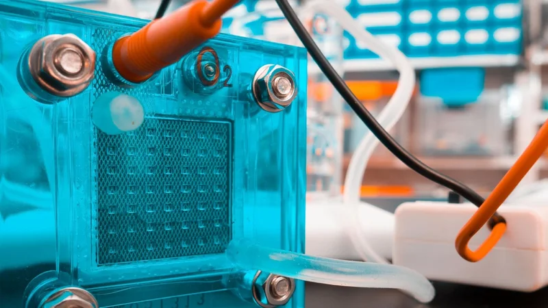
A PEM fuel cell setup in a laboratory
Key Takeaways
A PEM fuel cell runs at roughly 60 °C to 80 °C and produces about 0.7 V per cell in air, so useful voltage comes from stacking hundreds of cells in series.
The proton exchange membrane is a sulfonated fluoropolymer, usually Nafion, that conducts protons only when hydrated. Water management is therefore the central control problem.
Thermodynamics caps efficiency at 83% at 25 °C and 80% at 80 °C, but real systems deliver about 60% on pure hydrogen because of activation, ohmic, and mass transport losses.
Platinum loading has fallen from 28 mg/cm² in the 1960s to 0.3 mg/cm² in current heavy-duty designs, which shifts the dominant cost to bipolar plates and balance of plant.
Hydrogen must meet ISO 14687 Grade D (99.97% minimum), because carbon monoxide above 0.2 µmol/mol poisons the platinum catalyst.
What Is a PEM Fuel Cell?
A PEM fuel cell, short for Proton Exchange Membrane fuel cell, is an electrochemical device that converts the chemical energy in hydrogen directly into electrical power. Polymer electrolyte membrane (PEM) fuel cells are the same technology under a different name, and you will see both terms in the literature.
The interesting bit is that PEM fuel cells perform this conversion without combustion, so they’re not bound by the Carnot limit that constrains combustion engines.
The defining feature is the electrolyte, a thin, solid polymer sheet that conducts protons but blocks electrons and gas. Because that solid electrolyte is a plastic film rather than a molten salt or a ceramic, the cell operates at low temperature, starts quickly, and works in any orientation.[1]
The U.S. Department of Energy classifies PEM as operating under 120 °C, with stack sizes from under 1 kW to 100 kW and about 60% electrical efficiency on direct hydrogen, dropping to roughly 40% on reformed fuel.[2]
That combination of low weight, high power density, and quick startup is why proton exchange membrane fuel cells dominate transport applications while other chemistries hold the high-temperature stationary market.
Suggested Reading: What Is a Fuel Cell? Theory, Components, Types, and Applications
How a PEM Fuel Cell Works
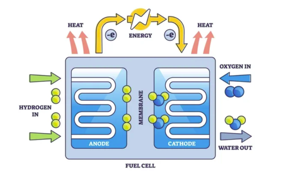
The cell splits one chemical reaction into two half-reactions and forces the electrons to take a detour through your load.
The two half-reactions
At the anode, a platinum catalyst strips hydrogen atoms of their electrons. This oxidation reaction produces protons and electrons:
Anode: H₂ → 2H⁺ + 2e⁻
The protons migrate through the membrane toward the cathode. The electrons cannot cross the membrane, so they travel through the external circuit instead, and that flow is the electric current you use.[3]
At the cathode, oxygen gas from the air combines with the returning electrons and the arriving protons:
Cathode: ½O₂ + 2H⁺ + 2e⁻ → H₂O
Overall: H₂ + ½O₂ → H₂O
The only products of this electrochemical reaction are water and heat. At the point of use, there are no greenhouse gas emissions or air pollutants, though upstream emissions depend entirely on how the hydrogen was made.
The Need for a Stack
A single cell produces only about 0.7 V when operating on air.[1] That is set by thermodynamics and losses, not by cell size: making the cell bigger increases current, not voltage.
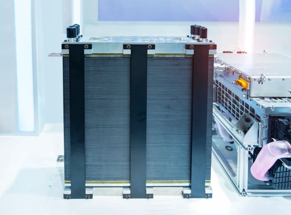
To get a useful bus voltage, you connect cells in series. The second-generation Toyota Mirai stack, for example, uses 330 cells in series to deliver 128 kW from a 52 kg package.[4]
Current density is what scales power per unit area. Modern PEMFC designs run around 1 A/cm², a figure that has climbed steadily as membranes have gotten thinner and catalyst layers have improved.[1]
Inside the Cell
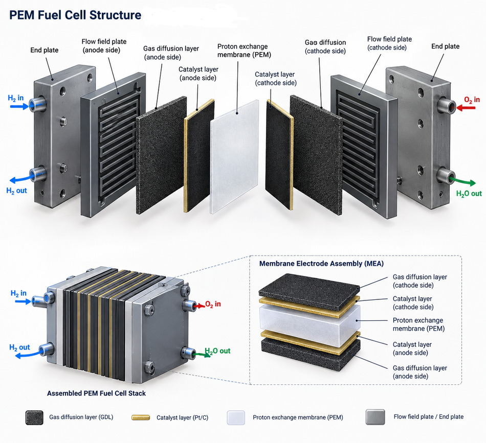
A PEMFC is built from repeating layers. This section elaborates on the role of each layer.
The Proton Exchange Membrane
Nafion is essentially PTFE carrying a fraction of pendant sulfonic acid groups. The perfluorinated backbone gives it chemical resilience in a hot, strongly acidic environment where hydrocarbon polymers would degrade quickly, plus enough mechanical strength to be made very thin.[5]
The ionic content is expressed as equivalent weight, meaning grams of dry polymer per mole of acid group. Useful equivalent weight for Nafion runs from 800 to 1500 g/mol, with 1100 g/mol as the common standard.[5]
Those sulfonic acid groups are extremely acidic, with a pKa around -6, so they dissociate readily and release the protons that carry charge.[5] Protons travel as hydronium ions, with Zundel (H₅O₂⁺) and Eigen (H₇O₃⁺) structures mediating transfer between hydrated clusters.
Since conductivity depends on water content, it becomes a critical design issue. A dry membrane is an insulator. Typical proton exchange membrane conductivity is 0.01 to 0.1 S/cm at 80 °C to 90 °C, spanning a full order of magnitude depending purely on hydration state.[5]
Manufacturer data for extruded Nafion membranes show how thickness is traded against strength and resistance:
Grade | Thickness (µm) | Basis weight (g/m²) |
Nafion N115 | 127 | 250 |
Nafion N117 | 183 | 360 |
Nafion N1110 | 254 | 500 |
Research from Chemours specifies a minimum conductivity of 0.10 S/cm, total acid capacity of 0.95 to 1.01 meq/g, and water uptake of 38% by weight from dry to water-soaked at 100 °C.[6]
That swelling has an important mechanical effect. It increases thickness by about 10% when soaked at 23 °C and 14% at 100 °C, so a stack clamped dry will see changing compression as it wets.
A thinner membrane has less ohmic resistance, but it’s more prone to mechanical failure and gas crossover.
Automotive stacks therefore use reinforced membranes far thinner than the N117 grade used in laboratory work.
Catalyst Layers and Platinum
Both electrodes need a platinum catalyst as the oxygen reduction reaction at the cathode is sluggish at low temperature. This is the single biggest chemical constraint on PEMFC cost.
The progress here is worth quantifying. Early General Electric cells required 28 mg of platinum per cm² of electrode. Modern designs use 0.2 mg/cm² or less, roughly 1% of the original loading.[1]
Current DOE cost modeling for a 275 kW heavy-duty truck system assumes a cathode loading of 0.30 mg Pt/cm², reduced from 0.40 mg/cm² in the previous year's analysis, with total loading falling from 0.45 to 0.35 mg Pt/cm². That single change cut modeled system cost by about $15/kW.[7]
As platinum is quite expensive, the catalyst is no longer the dominant cost. The bipolar plate has become the most expensive part of a modern cell.[1]
Gas Diffusion Layers
The gas diffusion layers sit between the catalyst layers and the plates. They are porous carbon structures, usually treated with PTFE to make them hydrophobic.
They do three jobs at once:
Spread reactant gas evenly across the catalyst area
Conduct electrons from the catalyst to the plate
Wick liquid product water away from the cathode so it does not block the gas path.
A critical factor here is the hydrophobicity. Getting it wrong in either direction costs performance.
Bipolar Plates and Flow Fields
A bipolar plate connects the anode of one cell to the cathode of the next, while keeping their gases separate and often carrying coolant as well.
The material requirements are demanding and mutually antagonistic. Published criteria call for electrical conductivity above 10 S/cm, thermal conductivity of 20 W/m/K with integrated cooling (or 100 W/m/K if heat leaves through the edges), gas permeability below 10⁻⁷ mbar·L/s/cm², stiffness above 25 MPa, and corrosion resistance in a hot, humid, acidic environment.[1]
Flow channels are typically about 1 mm wide and deep. The layout is a genuine engineering trade-off:
Parallel channels give low pressure drop, but if water blocks one channel, the gas simply diverts to the others, and the blockage never clears.
Serpentine channels guarantee that flow sweeps the whole path and clears blockages, at the cost of much higher pressure drop and parasitic pumping power.
Hybrid designs split the difference and are what most production plates actually use.[1]
Internal manifolding, where channels stop short of the plate edge, seals far better than external manifolding and makes integrated cooling practical.
PEM Fuel Cell Efficiency
The energy available to do electrical work is the Gibbs free energy change of the reaction, while the total energy released is the enthalpy change. The ratio of the two is the thermodynamic efficiency limit, and it falls as temperature rises. Consider the following table.[8]
Temperature (°C) | ΔGf (kJ/mol) | Max reversible EMF (V) | Efficiency limit |
25 (liquid water) | -237.2 | 1.23 | 83% |
80 (liquid water) | -228.2 | 1.18 | 80% |
100 | -225.2 | 1.17 | 79% |
200 | -220.4 | 1.14 | 77% |
1000 | -177.4 | 0.92 | 62% |
There are two practical points worth discussing:
Heating Value
The quoted efficiency depends on whether you divide by the higher heating value (liquid water product, -285.8 kJ/mol) or the lower heating value (steam, -241.8 kJ/mol), so always check which basis a datasheet uses.[8]
Hydrogen-Specific Falling Limit
Second, the falling limit with temperature is specific to hydrogen. A carbon monoxide-fueled cell drops from 82% at 100 °C to 52% at 1000 °C, while a methane-fueled cell reaction barely changes.[8] This is why you cannot generalize "low temperature is more efficient" across fuel cell chemistries.
Against that 80% ceiling at 80 °C, a real PEM system delivers about 60% on pure hydrogen.[2] The gap is the sum of three loss mechanisms, visible as the three regions of a polarization curve:
Activation losses dominate at low current density and come from the slow oxygen reduction kinetics at the cathode. This is what pulls open-circuit voltage below the theoretical 1.23 V.
Ohmic losses dominate in the middle of the curve and scale linearly with current. Membrane resistance is the biggest contributor, which is why hydration and thickness matter so much.
Concentration losses appear at high current density, when the reactant cannot reach the catalyst fast enough. Flooding makes this region arrive much earlier.
Designers usually pick an operating point around 0.6 V to 0.7 V per cell, because that balances efficiency (which favors high voltage) against power density and capital cost (which favor high current). This is why DOE stack targets are specified at 0.7 V.[7]
Water Management
Water management is the defining operational challenge of a PEM fuel cell, and it is a genuine balancing act rather than a solved problem.
The membrane must stay hydrated to conduct protons. But the cathode produces liquid water, and too much of it floods the gas diffusion layers and catalyst layers, blocking reactants from reaching the catalyst.
Two transport mechanisms fight each other across the membrane. Electro-osmotic drag pulls water from anode to cathode as protons migrate, with a drag coefficient of roughly 1.0 for a vapor-equilibrated membrane and about 2.5 when liquid-equilibrated at room temperature. Back diffusion pushes water the other way down the concentration gradient.[9]
Because drag typically wins at high current, you can get the counterintuitive failure mode of a dry anode and a flooded cathode at the same time. Symptoms differ usefully:
Dry-out shows up as rising ohmic resistance and a voltage drop that worsens steadily with current, often after operating hot or at low humidity.
Flooding shows up as unstable, fluctuating voltage and a sharp drop at high current, often after operating cool or at high humidity.
Hydrogen Purity and Quality
The platinum catalyst that makes low-temperature operation possible also makes the cell sensitive to contamination. Carbon monoxide adsorbs onto platinum sites and blocks hydrogen from reacting.
ISO 14687 Grade D sets the fuel specification for proton exchange membrane fuel cells in road vehicles. Consider the following limits.[10]
Characteristic | Maximum limit |
Hydrogen fuel index (minimum) | 99.97% mole fraction |
Total non-hydrogen gases | 300 µmol/mol |
Carbon monoxide | 0.2 µmol/mol |
Total sulfur compounds (H₂S basis) | 0.004 µmol/mol |
Ammonia | 0.1 µmol/mol |
Formaldehyde | 0.01 µmol/mol |
Formic acid | 0.2 µmol/mol |
Total halogenated compounds | 0.05 µmol/mol |
Water | 5 µmol/mol |
Oxygen | 5 µmol/mol |
Total hydrocarbons (methane basis) | 2 µmol/mol |
Carbon dioxide | 2 µmol/mol |
Particulates | 1 mg/kg |
The sulfur limit of 4 parts per billion is needed because sulfur poisoning of platinum is effectively irreversible, unlike CO poisoning, which can be partly recovered.
This purity requirement is why a PEM fuel cell cannot run directly on natural gas or methanol. Those fuels must first be converted in a reformer, and the reformate then needs cleanup to reach Grade D.[3]
Suggested Reading: Dirty water boosts prospects for clean hydrogen
PEM Compared With Other Fuel Cell Types
Choosing a fuel cell chemistry is mostly a question of operating temperature, which then determines fuel flexibility, start-up time, and materials cost. Consider the following comparison.[2]
Type | Electrolyte | Temperature | Typical stack size | Efficiency |
PEMFC | Perfluorosulfonic acid polymer | Under 120 °C | Under 1 kW to 100 kW | 60% direct H₂, 40% reformed |
Alkaline fuel cells (AFC) | Aqueous KOH or alkaline polymer | Under 100 °C | 1 to 100 kW | 60% |
Phosphoric acid fuel cells (PAFC) | Phosphoric acid in porous matrix | 150 to 200 °C | 5 to 400 kW | 40% |
Molten carbonate (MCFC) | Molten Li, Na, K carbonates | 600 to 700 °C | 300 kW to 3 MW | 50% |
Solid oxide fuel cells (SOFC) | Yttria-stabilized zirconia | 500 to 1000 °C | 1 kW to 2 MW | 60% |
PEM is suitable when we require:
Quick startup
Low Weight
High Power Density
Frequent Cycling
On the other hand, solid oxide fuel cells and MCFC are effective where you run continuously at scale and can use the high-grade waste heat, which is why SOFC dominates large stationary power generation.
Alkaline fuel cells are cheap but sensitive to CO₂ in air. A direct methanol fuel cell (DMFC) trades efficiency for the convenience of a liquid fuel, which suits low-power portable power applications where energy density beats efficiency.
Note also that the same membrane technology runs in reverse. PEM electrolysis splits water into hydrogen and oxygen, and the electrolysis stack shares the membrane, catalyst, and plate technology of the fuel cell.[11]
High-Temperature PEM Fuel Cells
A variant worth knowing about replaces the hydrated Nafion membrane with phosphoric acid-doped polybenzimidazole (PBI), pushing operation to 100 °C to 200 °C.
It offers significant advantages as there is no need for external humidification, simpler water management, a smaller radiator, better electrode kinetics, and dramatically higher CO tolerance, which loosens the fuel purity requirement enough to pair the stack directly with a reformer.
At the same time, the costs are equally real. Conductivity of pure PA-PBI is below 10 mS/cm at 180 °C, well under a hydrated Nafion membrane, though doped formulations reach 0.106 S/cm at 170 °C.
Phosphoric acid also leaches out during shutdown as water condenses, and phosphate anions adsorb onto the platinum.[12]
Cost and Durability: Where the Technology Actually Stands
This is where marketing claims and engineering reality diverge most, so the numbers matter.
DOE technical targets for an 80 kW transportation system set the benchmark [13]:
Characteristic | 2015 status | 2020 target | Ultimate target |
System cost ($/kW net) | 53 | 40 | 30 |
Peak energy efficiency | 60% | 65% | 70% |
Power density (W/L) | 640 | 650 | 850 |
Specific power (W/kg) | 659 | 650 | 650 |
Durability (hours) | 3,900 | 5,000 | 8,000 |
Cold start at -20 °C (s) | 20 | 30 | 30 |
Heavy-duty applications are much more demanding because a truck accumulates hours far faster than a car. DOE cost modeling for a 275 kW Class 8 truck system assumes 25,000 hours of durability and puts stack cost at $95/kW net at 50,000 systems per year in the 2024 analysis, projected to fall to $61/kW by 2030 on the back of higher power density (642 to 953 mW/cm² at 0.7 V at end of life).[7]
Real-world durability data is a useful sanity check. Analysis of fuel cell transit buses operating between 2011 and 2017 found an average degradation rate of 1.3% per 1,000 hours, reaching 20% degradation after 17,000 hours and 10% after 8,500 hours. Twelve of the fifteen power plants studied surpassed 25,000 hours of operation, and one exceeded 32,000 hours.[14]
Recommended Reading: Making hydrogen fuel cells 'less precious'
Where PEM Fuel Cells Are Used
Fuel cell electric vehicles: The most visible application for fuel cells is with electrical vehicles. The second-generation Toyota Mirai carries 5.6 kg of compressed hydrogen and a 128 kW stack achieving 5.4 kW/L, giving a range around 640 km.[4][15]
Heavy trucks and buses: Currently the fastest-growing segment, where long range and fast refueling beat batteries on duty cycle. China holds almost 95% of global fuel cell commercial vehicle stock.[16]
Material handling: Forklifts are a mature commercial market, because a 3-minute refuel replaces a battery swap and voltage stays flat through a shift, which matters in multi-shift warehouses.
Backup power and data centers: Quick startup and quiet, emission-free operation at the point of use suit backup power for telecom sites and data centers, where diesel generators face tightening restrictions.
Portable power: Low weight and low volume relative to other fuel cell types make PEM the usual choice for portable and auxiliary units.[11]
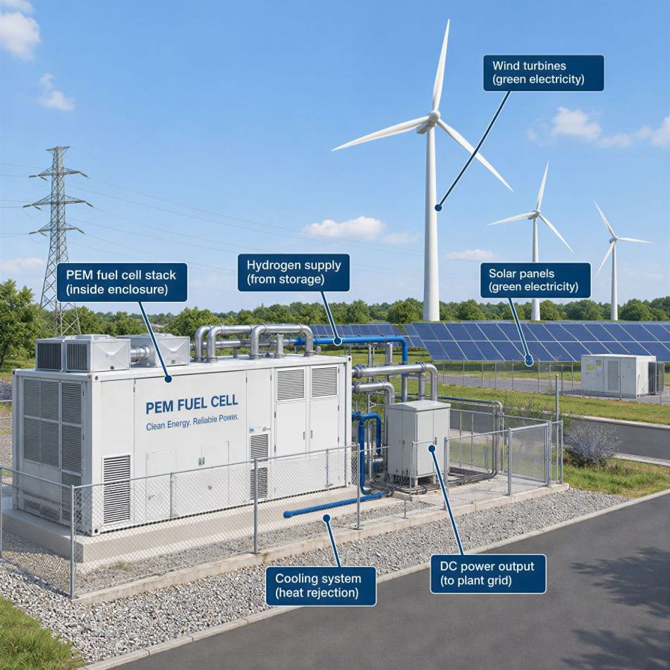
Stationary power generation: PEM plays here, though the high-temperature chemistries usually win at large scale.[3]
Recommended Reading: New fuel cell could enable electric aviation
Design Considerations and Common Mistakes
If you are specifying or building with PEM fuel cells, these are the errors that show up most often:
Treating the stack as a battery replacement: A fuel cell has a soft output characteristic and responds relatively slowly to load transients. Almost every practical system hybridizes with a battery to handle peaks and capture regenerative braking.
Ignoring balance of plant: The stack is only part of the system. Air compressor, humidifier, water separator, filters, and thermal management add cost, parasitic load, and failure modes. DOE flags both the humidifier (5,000 to 6,000-hour life) and air compressor bearings as unable to reach 25,000 hours without replacement.[7]
Underestimating air filtration: The cathode breathes ambient air, and airborne contaminants poison the catalyst just as fuel contaminants do.
Specifying hydrogen loosely: "High purity" is not a specification. Cite ISO 14687 Grade D and require certification, or you will pay for it in stack life.
Neglecting freeze behavior: Product water inside a stack freezes. Cold start capability from -20 °C requires a purge strategy at shutdown and is an explicit DOE target for good reason.[13]
Comparing efficiencies on different bases: An LHV number and an HHV number differ by about 18% for hydrogen. Make sure you are comparing like with like.[8]
For a system-level design, budget your voltage first: decide the cell count from your required bus voltage at roughly 0.65 V per cell under load, then set active area from your peak current, then oversize for end-of-life degradation.
Suggested Reading: New liquid can simplify hydrogen transportation and storage
Conclusion
A PEM fuel cell is a mature, well-characterized technology whose behavior follows directly from one design choice: a hydrated polymer electrolyte that only works in a narrow temperature and humidity window. Everything else, from platinum loading to water management strategy to hydrogen purity specifications, is a consequence of that choice.
The engineering problems that remain are cost and durability rather than fundamental performance. Platinum loading has already fallen by two orders of magnitude, shifting attention to bipolar plates and balance of plant. Durability of 25,000 hours is demonstrated in transit service but not yet routine.
Frequently Asked Questions
1. What does PEM stand for in a fuel cell?
PEM stands for both proton exchange membrane and polymer electrolyte membrane. The two terms are used interchangeably for the same technology, and you will see proton exchange membrane fuel cells abbreviated as PEMFC in technical literature.
2. What is the operating temperature of a PEM fuel cell?
Standard low-temperature PEMFCs run at roughly 60 °C to 80 °C, and DOE classifies the category as operating under 120 °C.[2] High-temperature variants using phosphoric acid-doped PBI membranes operate from 100 °C to 200 °C.
3. How efficient is a PEM fuel cell?
The thermodynamic limit is 83% at 25 °C and 80% at 80 °C.[8] Real systems achieve about 60% electrical efficiency on pure hydrogen and around 40% on reformed fuel.[2] By comparison, internal combustion engines typically convert 20% to 35% of fuel energy to work.
4. Why do PEM fuel cells use platinum?
The oxygen reduction reaction at the cathode is kinetically slow at low temperatures, and platinum is the most effective catalyst that survives the acidic environment. Loading has dropped from 28 mg/cm² in 1960s designs to about 0.3 mg/cm² today, which is why platinum is no longer the dominant cost.
5. How long does a PEM fuel cell last?
DOE's ultimate target for light-duty transport is 8,000 hours. Heavy-duty targets are 25,000 hours. Transit buses have demonstrated 17,000 hours to 20% degradation in real service, with individual units exceeding 32,000 hours.
6. What is the difference between a PEM fuel cell and a PEM electrolyzer?
They are the same technology running in opposite directions. A fuel cell consumes hydrogen and oxygen to make electricity and water. PEM electrolysis consumes electricity and water to make hydrogen and oxygen, using the same membrane, catalyst, and plate architecture.
References
Proton exchange membrane fuel cells (PEMFCs), low temperature cells, DoITPoMS, University of Cambridge.
Comparison of Fuel Cell Technologies, U.S. Department of Energy.
Fuel Cell Basics, U.S. Department of Energy.
Toyota Mirai Technical Specifications, Toyota UK Media.
Proton exchange membrane fuel cells: Membrane, DoITPoMS, University of Cambridge.
Nafion PFSA Membranes N115, N117, N1110 Product Information, Chemours.
Fuel Cell Cost and Performance Analysis, 2024 Annual Merit Review, Strategic Analysis for the U.S. DOE Hydrogen Program.
Proton exchange membrane fuel cells: Efficiency and reaction conditions, DoITPoMS, University of Cambridge.
Modelling the Proton-Conductive Membrane in Practical PEMFC Simulation: A Review, PMC.
Hydrogen Fuel Quality Specifications for Polymer Electrolyte Fuel Cells in Road Vehicles, U.S. Department of Energy.
Frequently Asked Questions About PEMs, Chemours Nafion.
DOE Technical Targets for Fuel Cell Systems and Stacks for Transportation Applications, U.S. Department of Energy.
On-Road Transit Bus Fuel Cell Stack Durability, Program Record 20008, U.S. DOE Hydrogen and Fuel Cell Technologies Program.
New Mirai hydrogen fuel cell vehicle, under the skin, Toyota UK.
Global Hydrogen Review 2025, Demand, International Energy Agency.
in this article
1. What Is a PEM Fuel Cell?2. How a PEM Fuel Cell Works3. Inside the Cell4. PEM Fuel Cell Efficiency5. Water Management6. Hydrogen Purity and Quality7. PEM Compared With Other Fuel Cell Types8. High-Temperature PEM Fuel Cells9. Cost and Durability: Where the Technology Actually Stands10. Where PEM Fuel Cells Are Used11. Design Considerations and Common Mistakes12. Conclusion13. Frequently Asked Questions14. References