Data Link Layer Design Issues: An integral element of every Network Stack
The data link layer in the OSI model is responsible for seamless video calls and swift file transfers. This article will dive deep into its mechanisms and operations appreciating how the layer silently powers our interconnected world.

Last updated on 06 Jul, 2024. 18 minutes read
Introduction
The Data Link Layer (DLL) is the second layer in the ISO’s OSI model, playing the most critical role in computer networks. Data link layer plays a key role in managing how the data packets are encoded, transmitted, and received across physical networks. It ensures reliable communication across network nodes through error detection, correction, and framing methods.
Understanding and optimizing the Data Link Layer helps ensure reliable network operations. Fixing design issues at this layer impacts the network performance, causing transmission errors, data loss, increased latency, and reduced efficiency. This article will delve into key concepts such as Medium Access Control (MAC), error control techniques, and flow control mechanisms.
Grasping the Basics: Foundational Concepts of the Data Link Layer
The data link layer, positioned as the second layer in the OSI (Open Systems Interconnection) model, is fundamental to network communication. Developed in the early 1980s, the OSI model provided a standardized framework that revolutionized networking by breaking down complex communication systems into manageable layers [6].
The data link layer bridges the physical and network layers, ensuring that data is transferred reliably across the physical medium. This layer is responsible for framing, which involves dividing data into manageable units called data frames. It also helps in physical addressing using hardware addresses known as MAC (Media Access Control) addresses. Error detection and correction are critical functions of the data link layer that identify and correct errors during transmission checksum.
The Role of the Data Link Layer in the OSI Model
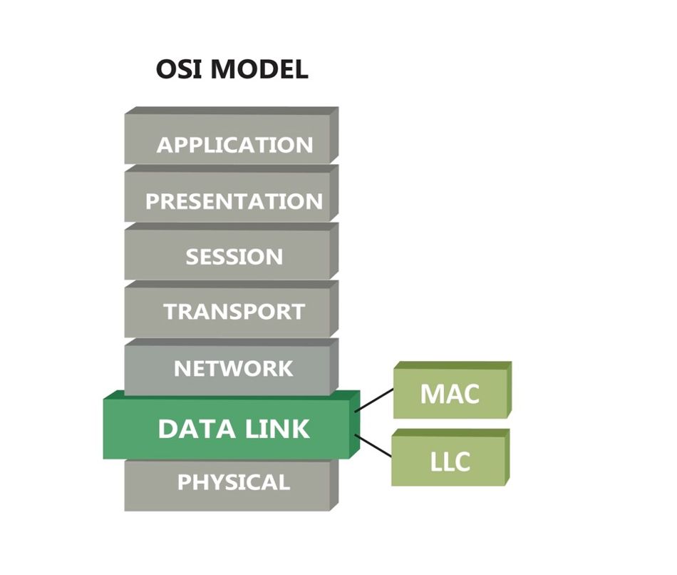
The OSI (Open Systems Interconnection) model is a conceptual framework for understanding and implementing network protocols in seven layers namely the Physical Layer, Data Link Layer, Network Layer, Transport Layer, Session Layer, Presentation Layer, and Application Layer. The data link layer, located above the physical layer and below the network layer, plays a crucial role in facilitating communication between these layers. It takes raw bits from the physical layer, organizes them into frames, and ensures that these frames are error-free and properly sequenced before passing them to the network layer. This layer handles both the Logical Link Control (LLC), which manages frame synchronization and flow control, and the medium access control (MAC), which governs how devices share the transmission medium. In practical terms, consider how Ethernet and Wi-Fi, two ubiquitous networking technologies, rely on data link layer protocols to function seamlessly, handling everything from data packet organization to collision detection and avoidance. The service interface provided by this layer is essential for the proper functioning of upper layers.
Recommended Readings: Understanding Modbus TCP-IP: An In depth Exploration
Key Functions and Responsibilities
The data link layer performs several essential functions to maintain robust and efficient network communication:
The data link layer performs several essential functions to maintain robust and efficient network communication:
- Framing: Divides the data stream into manageable units called frames. Each frame includes a header and trailer that contain control information for addressing and error detection. It is possible to identify the beginning and end of a frame based on a specified sequence of bits. This bit sequence is added in the frame to denote its boundaries. The method is called bit stuffing. Bit stuffing is implemented in many data link layer instances, including the data link layer of the popular USB (Universal Serial Bus) protocol.
- Flow Control: Manages the rate of data transmission between sender and receiver to prevent overwhelming the receiving device. Protocols like the sliding window mechanism are used extensively in reliable data transfer scenarios, such as in TCP/IP networks. These mechanisms are vital for slow receivers and fast senders.
- Error Detection and Correction: Implements techniques like CRC (Cyclic Redundancy Check) to detect and correct errors during data transmission, ensuring data integrity. Advanced error correction methods, such as Reed-Solomon codes, are increasingly important in high-reliability applications, including satellite and deep-space communication.
- Physical Addressing: Utilizes MAC addresses to identify devices on the network. These hardware addresses ensure that data is delivered to the correct device, or destination machine. In a Wi-Fi network, MAC addresses help route data to the appropriate wireless devices without interference.
- Access Control: Regulates access to the shared transmission medium, using protocols like CSMA/CD (Carrier Sense Multiple Access with Collision Detection) to avoid collisions and ensure efficient communication. Emerging technologies, such as the Internet of Things (IoT), pose new challenges and opportunities for medium access control, requiring innovative solutions to manage numerous connected devices efficiently.
By understanding these foundational concepts and their real-world applications, network engineers can better appreciate the complexities of data link layer design and the critical role it plays in ensuring effective and reliable network communication.
Services provided by the Data Link to the Network layer
In the OSI model, the Data Link layer resides between the physical layer and the network layer. Hence, it receives bits from the physical layer and undertakes to deliver them in a proper format to the network layer. When sending data, messages leverage the network layer services first, invoke data link layer services, and end up sending data through the physical layer. At the receiving side, the reverse path is followed: bits from the physical layer are delivered to the data link layer, which then delivers the message to the network layer. Thus, the data link layer intermediates between the physical and the network layers to ensure the reliability of the delivery by structuring the data into well-defined frames.
The data link layer ensures that the network layer receives the data of the sender without any losses. It can also establish a logical communication channel between the sender and the receiver of a message by keep track of a virtual connection between them. Virtual connections are managed by the data link Layer. In this context, the data link layer provides to the network layer the following types of services:
- Unacknowledged Connectionless Service: This service ensures data delivery without errors. However, the transmitted data frames are independent of each other and are not subject to any acknowledgement from the destination machine regarding their proper delivery. The service is characterized as “connectionless” because the data link layer does not establish any virtual connection between the sender and the receiver. Likewise, the service is unacknowledged i.e., in case a frame is lost, there are no provisions for detecting the loss and recovering from it. In essence, a connectionless service provides no error control and no flow control. The most prominent example of a connectionless data link layer protocol is the popular Ethernet protocol.
- Acknowledged Connectionless Service: Like in the case of the previous service, this service does not establish and does not keep track of any virtual connection between sender and receiver. Nevertheless, contrary to the previous service, the receiver acknowledges packet delivery. Hence, the sender knows whether the data that it has transmitted are gracefully and safely received. Given that there is no virtual connection between sender and receiver, the various frames are acknowledged individually. In case no acknowledgement is received within a specified time interval, the sender resends the data frame. In this way, this service provides increased reliability when compared with the unacknowledged connectionless service. Acknowledged connectionless services are commonly used over unreliable physical channels such as wider Wi-Fi services.
- Acknowledged Connection-Oriented Service: This service establishes a logical connection between the server and the receiver. The establishment takes place prior to the transferring of any data. Accordingly, data is transmitted over the established logical connection. Moreover, in the scope of this service, frames are labelled with appropriate numbers to ensure that each of the frames is received only one time, while also certifying their proper order and sequence.
In practice the data link layer provides also framing services to the network layer i.e., it encapsulates the transmitted information in frames. The latter is picked up at the receiving side and passed to the network layer. Moreover, the data link layer offers addressing functionalities based on the use of hardware addresses that are unique on the network link. Such addresses are encoded in network devices (e.g., switches, network interface cards) by their OEM (Original Equipment Manufacturer). Also, the data link layer enables the synchronization of senders and receivers and offers this as a service to the network layer i.e., it prevents the need for the network layer to deal with synchronization issues. The framing and synchronization services are illustrated in the following paragraphs.
Navigating Design Challenges: Core Issues in Data Link Layer Design
The data link layer faces several design challenges that can impact overall network performance. These challenges have evolved alongside networking technologies, highlighting the ongoing need for innovation in high-performance networks. A few of these include:
- Error detection and correction
- Flow control
- Medium Access Control (MAC)
- Scalability
- Interoperability
Addressing these design challenges is essential as we discuss below.
Tackling Error Detection and Correction
In high-performance networks, maintaining data integrity is crucial to ensure reliable communication and efficient operation. Error detection and correction mechanisms are fundamental to achieving this goal. As data travels across various physical mediums, it is susceptible to corruption due to noise, interference, and other environmental factors. Robust error handling techniques are therefore essential to detect and correct these errors, ensuring that the transmitted data remains accurate and reliable.
Advanced Methods for Error Detection and Correction
Several advanced methods have been developed to enhance error detection and correction capabilities in networks. Historically, these techniques have evolved to address the growing complexities and demands of modern communication systems.
- Hamming Codes: Introduced by Richard Hamming in the 1950s, Hamming codes are a set of error-correction codes that can detect up to two simultaneous bit errors and correct one-bit errors. These codes add redundant bits to the original data, allowing the detection and correction of errors through parity checks. Hamming codes are widely used in computer memory systems and early communication systems, providing a balance between simplicity and effectiveness [1].
- Reed-Solomon Codes: These are block error-correcting codes that work by oversampling a polynomial constructed from the data. Developed in 1960 by Irving S. Reed and Gustave Solomon, Reed-Solomon codes are particularly effective in correcting burst errors, where multiple bits are corrupted in a sequence. They are widely used in digital communication and storage systems, such as CDs, DVDs, and QR codes. Their robustness in handling errors makes them ideal for media that require high reliability [2].
- Convolutional Codes: Unlike block codes, convolutional codes process data bits sequentially and use shift registers to generate parity bits. These codes, developed in the 1950s and 1960s, are highly effective in real-time error correction and are commonly used in applications such as mobile communications and satellite links. The Viterbi algorithm, introduced by Andrew Viterbi in 1967, is typically employed to decode convolutional codes efficiently, making them a staple in modern communication systems [3].
Comparison of Error Detection Techniques
| Technique | Error Detection Capability | Error Correction Capability | ComputationalComplexity | Applications |
| Hamming Codes | Single-bit and double-bit errors | Single-bit errors | Low | Computer memory, early communication systems |
| Reed-Solomon Codes | Multiple-bit (burst errors) | Multiple-bit errors | Moderate | Digital storage, optical media, QR codes |
| Convolutional Codes | Continuous bit streams | Multiple-bit errors | High | Mobile communications, satellite links |
Error detection and correction are integral to ensuring the reliability and efficiency of data transmission in high-performance networks. By employing advanced techniques such as Hamming codes, Reed-Solomon codes, and convolutional codes, networks can achieve higher levels of data integrity, supporting robust and efficient communication even in challenging environments. As new technologies emerge, these error handling methods will continue to evolve, addressing the ever-increasing demands of modern networked systems.
Ensuring Efficient Flow Control
Flow control is a crucial aspect of data communication, designed to manage the rate of data transmission between sender and receiver to prevent data loss and congestion. Without proper flow control mechanisms, a sender might overwhelm a receiver with too much data at once, leading to packet loss, increased latency, and reduced network efficiency. In general flow control functionalities are implemented based on two main approaches:
- Feedback-based Flow Control: In this case, the sender sends frames following the reception of ACK packets from the receiver.
- Rate-based Flow Control: In this case, the transmission rate is restricted without depending on an ACK from the receiver.
Other than these, it utilizes the below flow control mechanisms
Various Flow Control Mechanisms
Several flow control mechanisms have been developed to ensure efficient data transmission and prevent congestion in different network conditions:
- Stop-and-Wait ARQ: The stop-and-wait Automatic Repeat reQuest (ARQ) protocol is one of the simplest flow control mechanisms. In this method, the sender transmits a single frame and then waits for an acknowledgment from the receiver before sending the next frame. This ensures that the receiver processes each frame before receiving the next one, preventing buffer overflow. However, the stop-and-wait protocol can be inefficient in high-latency networks, as the sender spends a significant amount of time waiting for acknowledgments [4].
- Sliding Window Protocol: The sliding window protocol is more efficient than stop-and-wait ARQ. It allows the sender to transmit multiple frames before needing an acknowledgment, up to a specified window size. This window size represents the number of unacknowledged frames that can be in transit. As acknowledgments are received, the window slides forward, allowing new frames to be sent. This method improves throughput and reduces waiting time, making it suitable for high-latency networks. The protocol can be fine-tuned to balance the trade-off between throughput and memory usage by adjusting the window size. It operates in one of the following two modes:
- Go-Back-N ARQ (Automatic Repeat Request): In this mode, the sender transmits packets without a need to wait for an ACK packet. The number of packets that can be sent without an ACK is indicated by the size of a specified window (N). In cases, no errors are detected, and the sender has sent the packets of the N sized window in their correct order, the sender has to wait for an ACK prior to sending more packets.
- Selective Repeat ARQ: This mode focuses on retransmission of potentially damaged or lost data. Data transmission from the sender to receiver is continuous and not constrained by any window. The sender retransmits only the frames that have not been acknowledged. Hence, this mode results typically in fewer retransmissions and higher throughput than the previous one.
- Leaky Bucket Algorithm: The leaky bucket algorithm is a traffic shaping mechanism that controls data flow into a network at a steady rate. It works by buffering incoming data and releasing it at a constant rate, regardless of the burstiness of incoming traffic. The analogy of a leaky bucket helps to understand this mechanism: data enters the bucket at varying rates, but it leaks out at a fixed rate. This helps in smoothing out traffic bursts and maintaining a consistent data flow, which is particularly useful in preventing network congestion in environments with variable traffic loads [5].
Examples and Performance Analysis
- Stop-and-Wait ARQ in Low-Latency Networks: In a local area network (LAN) with minimal latency, the stop-and-wait ARQ protocol can perform adequately. Since the round-trip time for acknowledgments is low, the sender does not experience significant idle time, and the simplicity of the protocol ensures minimal overhead.
- Sliding Window Protocol in Wide Area Networks (WANs): For high-latency environments like WANs, the sliding window protocol offers significant performance improvements over stop-and-wait ARQ. By allowing multiple frames to be in transit, the protocol keeps the network pipe full, maximizing throughput. For instance, in a satellite communication system with a high round-trip time, adjusting the window size appropriately can help maintain high data transfer rates without overwhelming the receiver.
- Leaky Bucket Algorithm in Variable Traffic Environments: The leaky bucket algorithm is particularly effective in networks with fluctuating traffic patterns, such as internet service provider (ISP) networks. By smoothing out bursts of data and maintaining a steady flow, it helps prevent sudden spikes in traffic from causing congestion. For example, during peak usage times, the leaky bucket algorithm can manage data flow more effectively, ensuring a consistent quality of service for users.
Understanding and implementing these flow control mechanisms are essential for network engineers to ensure efficient and reliable data transmission, tailored to the specific conditions and requirements of their networks.
Overcoming Medium Access Control Challenges
Medium Access Control (MAC) is a crucial component in networking that manages how data packets are transmitted over a shared communication medium. In environments where multiple devices need to communicate over the same channel, the MAC layer is responsible for regulating access to avoid collisions and ensure efficient use of the medium. This layer sits within the data link layer of the OSI model and plays a vital role in coordinating the communication process.
Challenges Related to Shared Medium Access
In shared network environments, several challenges must be addressed for effective communication:
- Collision: When two or more devices attempt to send data simultaneously over the same channel, a collision occurs, leading to corrupted data. Effective MAC protocols are essential to detect and mitigate collisions to maintain data integrity.
- Contention: This occurs when multiple devices compete for access to the communication medium. Proper contention management helps to avoid delays and ensure fair access for all devices.
- Channel Allocation: Its complex to allocate channels efficiently to numerous devices. The MAC layer must dynamically allocate channels to maximize throughput and minimize interference.
MAC Protocols and Their Technical Specifications
Different MAC protocols have been developed to address these challenges, each with its technical specifications and use cases:
- CSMA/CD (Carrier Sense Multiple Access with Collision Detection)
- Technical Specifications: Devices listen to the network before transmitting. If the medium is free, they transmit data. If a collision is detected, devices stop transmitting, wait for a random period, and then try again.
- Applications: Widely used in traditional Ethernet networks.
- CSMA/CA (Carrier Sense Multiple Access with Collision Avoidance)
- Technical Specifications: Devices listen to the network before transmitting and use acknowledgments to confirm successful transmissions. This protocol minimizes collisions by using a backoff algorithm and is particularly effective in wireless networks where collisions are harder to detect.
- Applications: Standard in Wi-Fi (IEEE 802.11) networks.
- Token Passing
- Technical Specifications: A token circulates around the network, and only the device holding the token can transmit data. This method eliminates collisions and ensures organized access to the medium.
- Applications: Used in token ring networks and some industrial network protocols like ARCNET.
Effective medium access control is essential for ensuring reliable and efficient communication in shared network environments. By understanding and implementing appropriate MAC protocols, network engineers can overcome challenges related to collisions, contention, and channel allocation, thereby enhancing the performance and stability of the network.
Recommended Readings: Understanding Ring Topology: A Detailed Exploration
Leveraging Advances: Recent Technological Innovations
The rapid evolution of networking technology has led to significant advancements in addressing data link layer design issues. These innovations stem from cutting-edge research and development in new algorithms, hardware implementations, and industry standards, each contributing to the reliability of modern networks.
Advanced Error Control Techniques
The two notable innovations in error detection and correction are LDPC (Low-Density Parity-Check) codes and Turbo codes:
- LDPC Codes: LDPC codes are highly efficient error-correcting codes that provide near-capacity performance. They are extensively used in applications such as digital television, wireless communication standards (e.g., 5G), and data storage systems. These codes use sparse matrices to create long codewords, enabling robust error detection and correction with relatively low computational complexity. The adoption of LDPC codes in modern systems has greatly enhanced the reliability and efficiency of data transmission.
- Turbo Codes: Turbo codes are another powerful class of error-correcting codes known for their high performance. They combine two or more convolutional codes with an interleaver to improve error correction capability. Turbo codes are widely used in deep-space communication, 4G LTE, and other wireless communication systems. Their ability to approach the Shannon limit—the theoretical maximum efficiency of error correction—makes them a critical component in achieving high data rates and low error rates.
Enhanced Flow Control Protocols
Advancements in flow control protocols have focused on making data transmission more adaptive and dynamic to meet the demands of high-speed networks:
- Adaptive Flow Control Mechanisms: Modern networks implement adaptive flow control mechanisms that dynamically adjust the data transmission rate based on network conditions. For example, TCP Congestion Control algorithms, such as TCP Cubic and TCP BBR (Bottleneck Bandwidth and Round-trip propagation time), optimize data flow by monitoring network congestion and adjusting the send rate accordingly. These mechanisms ensure efficient data transmission, minimize packet loss, and improve overall network performance.
- Dynamic Flow Control Protocols: Protocols like the Stream Control Transmission Protocol (SCTP) offer dynamic flow control capabilities. SCTP is designed to transport multiple streams of data between two endpoints, reducing the likelihood of congestion and improving data transfer efficiency. In modern high-speed networks, SCTP is utilized in applications requiring robust and reliable data transport, such as telecommunication signaling and real-time media streaming.
Innovations in Medium Access Control
Advancements in MAC protocols and technologies have focused on improving efficiency, reducing collision rates, and supporting higher data rates in diverse networking environments:
- TDMA (Time Division Multiple Access): TDMA is a channel access method that divides the communication channel into time slots, allowing multiple devices to share the same frequency band without interference. Each device transmits in its assigned time slot, reducing the chances of collision and ensuring efficient use of the available bandwidth. TDMA is widely used in digital cellular systems, satellite communication, and some broadband wireless access networks.
- OFDMA (Orthogonal Frequency Division Multiple Access): OFDMA is a multi-user version of the OFDM (Orthogonal Frequency Division Multiplexing) digital modulation scheme. It splits the channel into multiple orthogonal subcarriers, allowing simultaneous data transmission from multiple users. OFDMA significantly enhances spectral efficiency, reduces latency, and supports higher data rates. It is a cornerstone technology in modern wireless communication standards such as 4G LTE and 5G NR (New Radio).
These technological innovations in error control, flow control, and medium access control are pivotal in advancing the capabilities of the data link layer. By leveraging these advancements, network engineers can design and implement more robust, efficient, and reliable networks, capable of meeting the growing demands of contemporary communication systems.
Addressing Broader Challenges: Scalability and Interoperability
As networking environments become increasingly complex, broader challenges such as scalability and interoperability emerge, impacting the effectiveness of data link layer design. These challenges extend beyond specific technical issues, requiring a comprehensive approach.
Scalability: Meeting Growing Network Demands
Scalability is a critical concern for the data link layer, especially as networks expand in size and complexity. As more devices connect and data traffic increases, the data link layer must efficiently manage this growth to maintain optimal performance. The historical development of the internet provides a backdrop to these challenges. Early networks, such as ARPANET, had to adapt quickly as the number of connected devices grew exponentially, leading to the creation of more robust protocols and hierarchical network structures.
- Scalability Challenges: One major challenge is the increasing number of devices that need to communicate simultaneously. This requires the data link layer to handle higher traffic volumes and more complex communication patterns without compromising speed or reliability. Additionally, network topologies are becoming more dynamic, with devices frequently joining and leaving the network, which can strain the data link layer's capacity. Real-world examples include the surge in IoT devices, which demands networks to support millions of concurrent connections.
- Hierarchical Design: This involves structuring the network into layers or tiers, where each layer manages a subset of devices. This reduces the load on individual nodes and improves overall network efficiency. For example, the hierarchical structure of cellular networks allows efficient management of large-scale user bases.
- Distributed Protocols: These protocols enable decentralized management of network resources, allowing the network to scale more effectively. Examples include distributed scheduling algorithms and load balancing techniques that evenly distribute traffic across the network. Technologies like blockchain also offer decentralized solutions that can enhance scalability in certain network applications.
Interoperability: Ensuring Seamless Communication
Interoperability is essential for seamless communication in diverse networking environments, where devices from multiple vendors and various technologies need to interact smoothly. The evolution of networking standards, such as Ethernet and Wi-Fi, underscores the importance of interoperability in driving widespread adoption and innovation.
- Defining Interoperability: In the context of data link layer design, interoperability refers to the ability of different systems and devices to work together effectively. This requires adherence to common standards and protocols to ensure compatibility. For instance, the IEEE 802.11 standards for wireless networking ensure that devices from different manufacturers can communicate seamlessly.
- Standardization and Compliance: Adopting universal standards, such as those developed by IEEE (Institute of Electrical and Electronics Engineers) and IETF (Internet Engineering Task Force), is crucial. These standards provide a common framework that all devices can follow, ensuring interoperability.
- Middleware Solutions: Middleware acts as an intermediary layer that translates and facilitates communication between different systems, helping bridge compatibility gaps.
- Firmware and Software Updates: Regular updates ensure that devices remain compliant with the latest standards and protocols, enhancing interoperability. Emerging technologies like 5G are also designed with interoperability in mind, supporting a wide range of devices and applications.
Addressing scalability and interoperability is vital for the data link layer to support the growing demands of modern networking environments. By implementing scalable designs and ensuring cross-vendor compatibility, network engineers can build robust, efficient, and future-proof networks.
Conclusion
Previous paragraphs have illustrated the main functionalities of the data link layer. They have also presented the techniques that are most widely used when implementing these functionalities. It is quite evident that the data link layer is very rich in functionalities. Therefore, its implementations are sometimes complex and challenging, yet important for the good functioning of most networking infrastructures. Most importantly, the data link layer functionalities include many concepts that are replicated and implemented in other layers as well. As a prominent example, error control and flow control functionalities are present in the transport layer. They are very important for ensuring reliable data delivery and for boosting the scalability and availability of the network. Likewise, connection-oriented and connectionless services are seen in many other protocol implementations. Overall, the data link layer does not only have practical value for the operation of modern networks. It is also an excellent educational device for researchers, engineers, and network practitioners.
FAQs
What is the data link layer and why is it important?
The data link layer is the second layer in the OSI model, responsible for ensuring reliable data transfer across the physical network. It handles framing, physical addressing, error detection and correction, flow control, and medium access control. Its role is crucial for maintaining data integrity and efficient communication between devices.
How do error detection and correction techniques work in the data link layer?
Error detection techniques, such as Cyclic Redundancy Check (CRC), detect errors in transmitted data by adding redundant bits. Error correction techniques, like Hamming codes, Reed-Solomon codes, and Turbo codes, not only detect but also correct errors by using algorithms that analyze the redundant bits to identify and fix errors. These methods are vital for ensuring data integrity in high-performance networks.
What are the main flow control mechanisms used in high-performance networks?
The main flow control mechanisms include stop-and-wait ARQ, sliding window protocol, and leaky bucket algorithm. These mechanisms manage the rate of data transmission to prevent congestion and data loss, ensuring smooth and efficient communication. For example, the sliding window protocol allows multiple frames to be sent before needing an acknowledgment, improving throughput in high-latency networks.
How do MAC protocols address challenges related to shared medium access?
MAC protocols, such as CSMA/CD, CSMA/CA, TDMA, and OFDMA, manage access to the communication medium to avoid collisions and ensure fair use. They employ different strategies to coordinate access among multiple devices, optimizing medium utilization and reducing interference. For instance, TDMA divides the communication channel into time slots, allowing multiple devices to share the same frequency band without interference.
Why is scalability important in data link layer design?
Scalability is important because networks are constantly growing in size and complexity. Scalable data link layer designs can handle increasing traffic volumes and more devices without compromising performance. Strategies like hierarchical design and distributed protocols help manage this growth effectively, ensuring that networks can expand seamlessly to meet future demands.
What is interoperability and how is it ensured in the data link layer?
Interoperability refers to the ability of different devices and systems to work together seamlessly. It is ensured through standardization and compliance with protocols developed by organizations like IEEE and IETF. Middleware solutions and regular firmware updates also help maintain interoperability across diverse devices and technologies, allowing for seamless communication and compatibility.
How are emerging technologies impacting data link layer design?
Emerging technologies like 5G and IoT are driving the need for more advanced error control, flow control, and MAC protocols. These technologies require networks to support higher data rates, lower latency, and a larger number of connected devices, pushing the boundaries of current data link layer designs and prompting innovation. For example, 5G networks employ advanced MAC protocols to manage the increased density of devices and high-speed data transmission, ensuring efficient and reliable communication.
References
[1] Prepbytes. HammingCode. Link
[2] CMU. Reed Solomon Code. Link
[3] MIT. Convolution Coding. Link
[4] GeeksforGeeks. Sop and Wait ARQ. Link
[5] GeeksforGeeks. Leaky bucket Algorithm. Link
[6] J. D. Day and H. Zimmermann, "The OSI reference model," in Proceedings of the IEEE, vol. 71, no. 12, pp. 1334-1340, Dec. 1983, doi: 10.1109/PROC.1983.12775.
in this article
1. Introduction2. Grasping the Basics: Foundational Concepts of the Data Link Layer3. Services provided by the Data Link to the Network layer4. Navigating Design Challenges: Core Issues in Data Link Layer Design5. Addressing Broader Challenges: Scalability and Interoperability6. Conclusion7. FAQs8. References