An Engineers' Guide to Bending Sheet Metal
Here we look at the basics of bending sheet metal, including bending radius, K-factor, and bend allowance calculations, helping you design manufacturable sheet metal parts.

30 May, 2025. 10 minutes read

Sheet metal bending is a foundational process in hardware manufacturing, used to create everything from server chassis and electronic enclosures to brackets and mounting panels. It is one of the most important forms of sheet metal fabrication, alongside other techniques like stamping and punching.
Bending sheet metal may look straightforward, but achieving accurate parts involves careful calculations and considerations. In fact, even seemingly simple sheet metal parts (think of brackets, covers, or chassis) must account for material deformation: the metal elongates when bent, which can throw off dimensions if not properly accommodated.
In this guide, we’ll walk through sheet metal bending basics and key concepts like bending radius, K-factor, and bend allowance. We’ll see how these factors influence the flat pattern development and final part dimensions. The article also looks at how to use CAD for sheet metal design, ensuring your digital models incorporate the correct parameters for manufacturing.
Sheet Metal Bending Basics
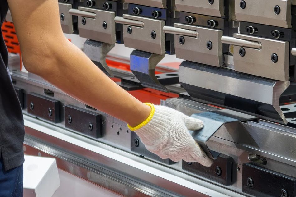
Bending sheet metal is the metalworking process of reshaping a flat metal sheet into a defined angle without breaking it, often using a press brake.[1] This involves placing the workpiece between a punch and die and applying force to form a bend. During bending, the outer portion of the sheet undergoes tension while the inner side experiences compression, causing the neutral axis—an imaginary line where no length change occurs—to shift toward the inner radius.[2] This shift results in a part whose outer length becomes slightly longer than its original flat layout.
Engineers have to consider many factors when designing parts for bending. For example, bends always produce rounded corners, not sharp angles, due to material limitations. And the design must also account for “springback”—the metal’s tendency to partially return to its original shape after bending. (Harder materials and larger radii lead to more springback, requiring fabricators to over-bend or use techniques like bottoming or coining.) Another important concept is bend allowance, which is the extra length needed to accommodate the stretch of the material along the neutral axis during bending. This must always be factored into the 2D flat pattern design.
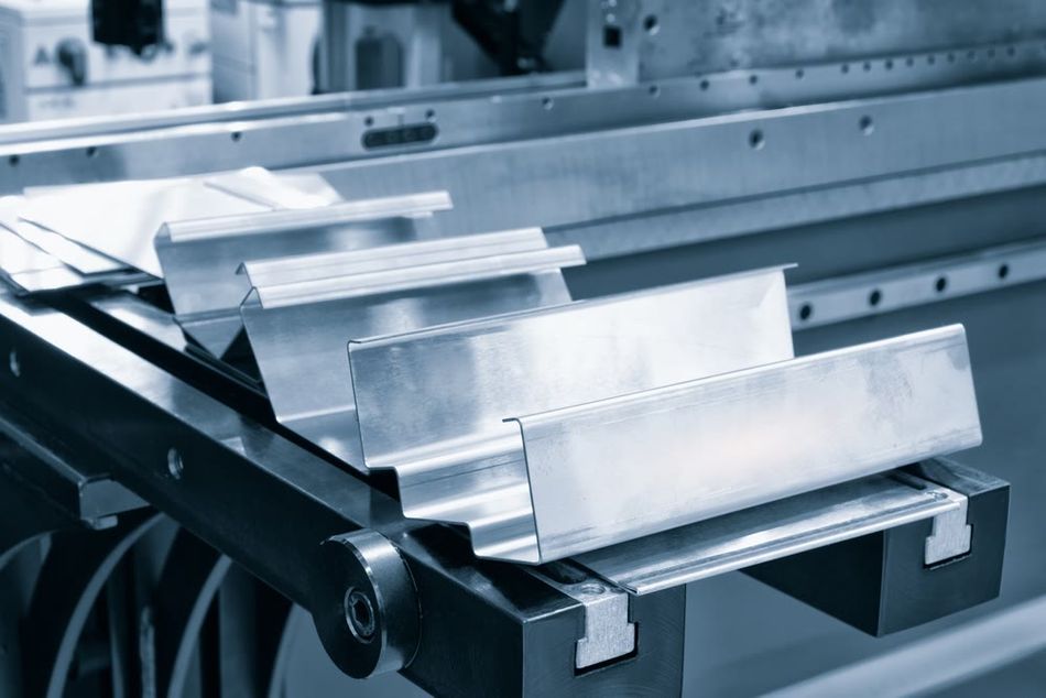
Sheet Metal Bending Hardware
Sheet metal bending is typically performed using a hydraulic press brake, and modern CNC (Computer Numerical Control) press brakes are the industry standard for high-precision work. These sheet metal brakes use programmable controls and back gauges to produce consistent bends with tight tolerances—typically around ±0.5° for angles and ±0.1–0.2 mm for linear dimensions like flange lengths. They can handle a wide variety of materials and thicknesses, and many support tooling changes to accommodate different bend radii, part geometries, or production volumes.
Simpler bending machines such as manual press brakes, leaf brakes, or pan brakes are also used, especially in prototyping, repair work, or low-precision applications. However, these bending tools have much looser tolerances and rely heavily on operator skill, making them less suitable for designs with tight stacking of bends or critical dimensions. In such cases, even with CNC equipment, achieving consistent results across multiple bends can be difficult due to tolerance “stack-up.” To overcome this, manufacturers may use custom fixtures, secondary machining operations, or dimensional inspection and adjustment steps to ensure final part accuracy.
Recommended reading: Sheet Metal Manufacturing: Innovating Industrial Techniques
Material Considerations
Not all sheet metals bend equally, so it’s important to choose the right one for a given part. The strength and ductility of the metal directly impact its ability to bend without cracking or deforming unpredictably. Softer, more ductile materials like aluminum and mild steel are easier to bend and exhibit less springback, whereas stronger materials like stainless steel or high-strength alloys are more resistant. These harder materials often require larger bend radii and more force to form.[3]
Grain direction is another important factor. Sheet metal has a grain, or rolling direction, from the manufacturing process. Bending parallel to the grain increases the risk of cracking, especially in brittle or work-hardened materials. To minimize cracking and improve bend quality, it’s generally recommended to bend perpendicular to the grain direction. (Designers should specify the grain direction on drawings when it matters to ensure consistent results in fabrication.)
Springback—the tendency of metal to partially return to its original shape after bending—varies depending on the material’s yield strength and modulus of elasticity. High-strength materials tend to exhibit more springback, requiring compensations like over-bending or using bottoming and coining methods. Material thickness also plays a role; thinner sheets typically bend more easily but may be more affected by springback if the radius-to-thickness ratio is small.
Material | Strength | Springback |
Mild Steel | Medium | Low |
Stainless Steel | High | High |
Aluminum | Low to Medium | Medium to High |
Copper | Low | Low |
Brass | Medium | Low to Medium |
K-Factor, Bend Allowance, and Bend Deduction
Understanding how bending affects flat pattern length can greatly help with sheet metal design—although good CAD software will do most of the work for you. For most purposes, the most important concepts to grasp are K-factor, bend allowance, and bend deduction.
The K-factor is a value used in sheet metal bending to describe how much the material stretches during a bend.[4] It represents the ratio between the distance from the inside surface of the bend to the neutral axis (the area that does not stretch or compress) and the total thickness of the material. In a flat state, the neutral axis sits at the center (K = 0.5), but during bending, it moves toward the inner surface. The exact K-factor depends on material type, thickness, bend radius, and the forming method. A lower K-factor indicates more stretching during bending, which increases the length of the material along the bend.
To determine how much material is used in a bend, engineers calculate the bend allowance (BA)—the length of the arc along the neutral axis. The formula is:
BA = θ × (R + K × T)
where θ is the bend angle in radians, R is the inside bend radius, and T is the material thickness. Once the bend allowance is known, the bend deduction (BD) can be used to calculate the flat length needed before bending. The formula is:
BD = 2 × (R + T) × tan(θ/2) – BA
Bend deduction shows how much material to subtract from the total length of the flanges to get an accurate flat pattern. While CAD software often handles these calculations, understanding how they work ensures better design decisions and helps prevent issues during fabrication.
CAD for Sheet Metal Design
Modern CAD software simplifies the task of designing bent sheet metal parts, whether you’ve fully grasped the above formulas or not. Packages like SolidWorks, Autodesk Inventor, and Fusion 360, and even free options like Onshape or Solid Edge, all have dedicated sheet metal design features. Below are some of the ways you can leverage CAD for efficient sheet metal design.
Sheet Metal Templates
In your CAD program, start a part using a sheet metal template or module. You’ll usually define a sheet thickness, default inside bend radius, and bend allowance (via K-factor or a bend table). These parameters ensure that all features you create (flanges, bends, hems, etc.) conform to that uniform thickness and use consistent bend rules. For example, you might set thickness = 1.0 mm, K-factor = 0.42, and inside radius = 1.0 mm for a stainless steel enclosure. Thereafter, every bend you add will assume those values unless you override them for specific bends.
Flange and Bend Features
Instead of drawing the final 3D shape directly, sheet metal CAD lets you design in a procedural way. Typically, you sketch the base shape (like a flat base panel) and then use a “flange” feature to extrude edges into flanges at a certain angle (often 90° by default). The software will automatically create the bend between the base and the flange with the correct radius and will calculate the bend allowance so that the flat pattern is correct.
You can also add bends to an existing flat wall using a “sketch bend” or “edge bend” tool, and CAD will again adjust the geometry to account for material stretch. This means you can focus on the functional dimensions (like the height of a flange, the enclosure width, etc.) and let the CAD worry about how the flat pattern needs to be cut.
Automatic Reliefs and Corner Treatments
Good CAD tools automatically insert bend reliefs when you create flanges that adjoin other flanges. A bend relief is a small notch or cut at the base of a flange where it meets another flange or wall. Its purpose is to prevent tearing or excessive deformation of the material at the corner of a bend.
For example, if you have two perpendicular flanges meeting at a corner, without a relief, the inside corner can pinch and tear. CAD will typically cut a small rectangular or tear-shaped relief so that when the part is flat, there’s a little gap that closes when bent. These relief dimensions can usually be set or are defaulted to about the material thickness in width.
Flat Pattern Generation
One of the most powerful features is the ability to unfold or flatten the model. With a click, CAD will generate the flat pattern layout. You can use this to check for any overlapping geometry and to output a DXF or drawing for fabrication. This flat pattern is directly informed by your K-factor/bend table settings. Many CAD programs allow you to annotate bend lines on the flat pattern with notes, which is helpful for the fabrication team or for documentation.
Manufacturer Design Tables
If your sheet metal fabricator provides a design guide, it may include recommended bend radius and allowance values for each material and thickness. Some CAD systems let you create a custom bend table, overriding the generic K-factor and using your manufacturer-specific values. This approach can yield very accurate parts on the first try, as it mimics the real-world results more closely. In absence of that, using a consistent K-factor (like 0.38 or 0.40 for steel) is often acceptable as a general approximation.
Design Feasibility
CAD can also help visualize if flanges will interfere during bending. Some software has a simulation feature where you can see the bending sequence. If a flange is too short or a tool can’t reach a bend, the part needs redesigning. Usefully, you can adjust the design (e.g., lengthen a flange or add a cutout) in CAD and immediately see the flat and formed outcome.
Recommended reading: The STEP File Format: A Technical Guide
Design for Manufacturability (DFM) Guidelines for Sheet Metal Bending
Designing with DFM in mind means anticipating the limitations of the bending process and ensuring your part can be fabricated properly by the manufacturer. The table below shows some of the most important rules to consider when designing sheet metal parts for bending.
Rule | Description | Example |
Use Appropriate Bend Radii | Use a consistent inside bend radius ≥ material thickness to ensure predictable bends and avoid cracking. | For 3 mm thick sheet, use a 3 mm radius on all bends. |
Ensure Minimum Flange Lengths | Flanges must be long enough for tooling to grip and form properly, typically ≥ 4× thickness + bend radius. | For 2 mm thick sheet with 2 mm radius: 4×2 + 2 = 10 mm flange length. |
Hole Placement Near Bends | Keep holes at least 3× material thickness + bend radius away from bends to prevent deformation. | In 1.5 mm thick sheet with 1.5 mm bend radius, holes should be ≥ 6 mm from the bend. |
Slot and Cutout Placement | Avoid placing slots too close to bends or parallel to bend lines; they may act as weak points. | Reinforce with bend relief or post-process slots if they must be near a bend. |
Add Bend Reliefs | Use relief cuts at the start/end of bends within material to prevent tearing or wrinkling. | A rectangular relief slightly wider than thickness and extending beyond bend tangent line. |
Use Adequate Notch and Tab Sizes | Notches and tabs should follow guidelines to avoid fragile features: notches ≥ thickness; tabs not longer than 5× their width. | Don’t use a narrow tab that's thinner than 2× material thickness. |
Maintain Bend Spacing | Leave space between adjacent bends to avoid distortion—typically ≥ 2–3× thickness. | If using 2 mm thick sheet, leave 4–6 mm between bend lines. |
Consistent Bend Orientation | Keep bend directions uniform to reduce tooling changes and streamline manufacturing. | Avoid mixing 90° and 45° bends unless necessary. |
Account for Tolerances | Use realistic tolerances; bend angles ±1°, lengths ±0.25 mm typical. Watch for accumulation over multiple bends. | Don’t specify ±0.1 mm across four bends unless post-processing is allowed. |
Account for Springback | Springback makes bends open slightly after release—use K-factor or over-bending to compensate. | For critical angles, over-bend slightly or specify compensation in CAD. |
Design Hems Correctly | For hems (folded edges), leave space for thickness doubling and consider proximity to nearby bends. | Fully closed hem doubles thickness—leave gap and spacing ≥ 5× thickness + bend and hem radii. |
Design Curls Properly | Curls (rolled edges) require outside radius ≥ 2× thickness and buffer distance from adjacent features. | Curl edge should not start too close to a bend or hole—leave material equal to curl radius as buffer. |
Place Hardware Away from Bends | Keep PEM inserts, studs, or welds away from bends—ideally insert after forming, or keep ≥ 3× thickness distance. | A PEM nut in a 2 mm sheet should be ≥ 6 mm from a bend. |
Consider Finishing Impacts | Bending can damage coatings—perform forming before painting/plating; also consider grain direction for visible surfaces. | Avoid bending anodized aluminum; align brushed finish direction consistently on cosmetic faces. |
Conclusion
Designing sheet metal parts is both an art and a science. In this guide, we’ve covered the scientific fundamentals (like how the K-factor and bend allowance help predict the stretching of metal) and best practices during design. To recap, always start with the basics: choose a suitable bend radius, apply known material K-factors or bend tables for your calculations, and use CAD tools to their fullest to avoid manual errors.
Fortunately for those of us who want to improve our bent sheet metal parts, this area of manufacturing is still evolving. Modern techniques like robotic bending cells and advanced simulation software are making it easier to predict and compensate for bending outcomes with even greater accuracy. And CAD integrations now can simulate bending sequences and even optimize part layouts for minimal waste and better end results.
As a final thought, always communicate with your fabricator. Each shop may have unique tooling or preferences (for example, they might prefer a specific minimum flange or have different stock radius tools). By involving them early, you can ensure that your carefully designed parts come out just right.
FAQ
Q: What is sheet metal bending and why is it important in design?
A: Sheet metal bending forms flat sheets into 3D shapes like brackets using tools like press brakes. It enables strong, lightweight designs without complex assemblies or castings.
Q: What is the K-factor in sheet metal bending?
A: The K-factor is the ratio of the neutral axis position to material thickness, used to calculate how much metal stretches during bending. It helps determine accurate flat patterns for forming.
Q: How do you calculate sheet metal bend allowance and bend deduction?
A: Bend allowance (BA) and bend deduction (BD) are formulas that adjust flat pattern lengths to match bent part dimensions. BA = θ × (R + K·T); BD = 2(R+T)tan(θ/2) – BA.
Q: What is the minimum bend radius for sheet metal, and why does it matter?
A: It’s the smallest bend you can make without cracking or deforming the metal, typically ≥ material thickness. Using too small a radius can ruin the part or cause manufacturing issues.
References
[1] Benson SD. Press Brake Technology: A Guide to precision sheet metal bending. Society of Manufacturing Engineers; 1997.
[2] Wang NM, Tang SC. Analysis of bending effects in sheet forming operations. International journal for numerical methods in engineering. 1988 Jan;25(1):253-67.
[3] Leu DK. A simplified approach for evaluating bendability and springback in plastic bending of anisotropic sheet metals. Journal of Materials Processing Technology. 1997 Apr 1;66(1-3):9-17.
[4] Karachalios E, Vairis A. The study of design of constants in sheet metal forming. InProceedings of the 2nd International Conference of “From Scientific Computing to Computational Engineering”, Athens, July 2006 (pp. 5-8).