6 Tips for Tackling Complex Features in Moulding Design
Mould-making techniques make complicated features like o-ring grooves, mushroom studs, and text on parts possible
Designing an injection-moulded part with the proper draft, wall thicknesses, radii, and other considerations can be complicated in itself, so when unique features like bayonets and gears are integrated into your geometry, another layer of complexity can arise. If your part requires intricate features, we’re often able to manufacture them through the use of side-actions, sliding shutoffs, pickouts, and other moulding methods. Here are some of the more commonly found complex features, and how they’re achieved.
Bayonet Mounts
Our capabilities allow for internal bayonet features in part design, which are created using relief holes and a sliding shutoff. The shutoff forms an internal through-hole in a part by bringing the A-side and B-side in contact, preventing the flow of resin into the through-hole. Protolabs requires at least 3 degrees of draft on bayonets.
O-Ring Grooves and Mushroom Studs
If you design a bayonet that contains an O-ring groove, Protolabs will use a two-piece pickout. A pickout is a detachable part of the mould that is manually inserted into the mould prior to the injection process and manually removed from the part after ejection (before the next cycle begins). An O-ring feature can also be made using two side-actions depending on its orientation, proximity to the parting line and freedom from interference from other features. Additionally, we support geometries that contain mushroom studs; those features are achieved similarly to O-rings, with a two-piece pickout or two side-actions. Note that with two-piece pickouts, there will be a witness line where they come together.
Text on Parts
Text on parts is used for different reasons, and if your design requires it, we typically recommend that it be raised above the part versus recessed into it; recessed text on parts are not only difficult to read, but raised letters in a mould make it difficult to achieve a good finish. It gets a bit more complicated depending on the location of the text on your part. Text extruded parallel with the mould’s open and close direction requires only a simple straight-pull mould to create the feature, but text extruded parallel to the parting line creates undercuts that require a side-action. A cam-operated side-action is used on the part’s mould because it operates automatically during the moulding process, which saves you production dollars in the end.
You can also design text on ribs. Instead of milling a long, thin rib, then milling even down farther to machine the tiny text, we use one of two options. A very small end mill (0.5mm) is used to first machine the text, then two bolted inserts create the rib afterward. The second option is electrical discharge machining (EDM) where a rapid series of electric sparks burn the desired text into the part. Both solutions will add cost to the mould. Finally, remember to apply draft to your text to facilitate easy release of the part from the mould.
Clips
Spring clips can be created in different ways, each with pros and cons. If a relief hole at the base of the clip and additional draft are acceptable, Protolabs can use a sliding shutoff to create an equally functional, yet less expensive clip. If a relief hole compromises your design, a side-action can be used to mould the clip, but it must be positioned to provide access from the outer parting line. A pickout is the most costly method to create the undercut in the clip, but it can overcome nearly every shape and positioning restriction. Material is also an important consideration in regards to clip functionality. The more rigid a material is, the harder it is to release a clip, so softer materials are used more for removable connections that see repetitive use.
Gears
A gear that is aligned parallel to the mould’s open and close direction is created with a simple straight-pull mould, but if the gear is deep, the faces on the gear teeth may need to be drafted to allow the gear to eject from the mould. Furthermore, if the tooth profile is very sharp or the teeth are small, an electrical discharge machining (EDM) electrode, in place of milling, may be required to form the gear.
Bosses
Bosses are essentially raised stud features used to engage fasteners or support features of other parts passing through them. Most bosses are relatively easy to mould; the challenge comes when they are placed on angled surfaces or are quite tall and thin. An angled boss is neither parallel to the mould open/close direction nor the parting line, which forms an undercut that is resolved with a pickout. If you have bosses that are tall and thin with a very high aspect ratio, Protolabs may use a steel core pin to ensure the pin doesn’t break during the moulding process.
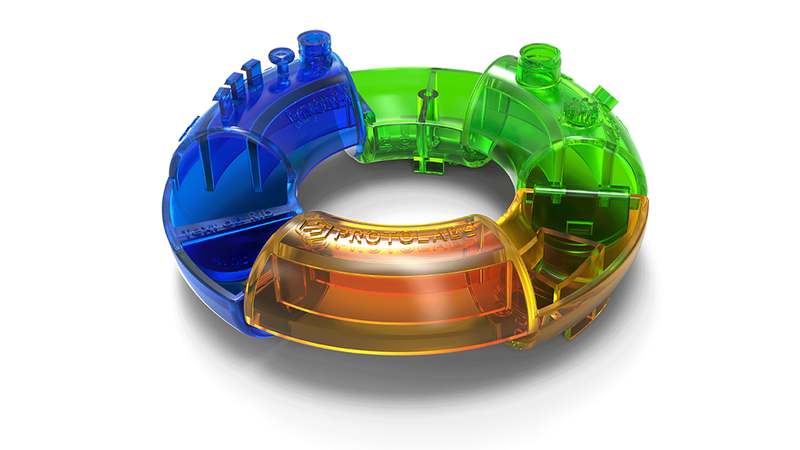
Protolabs has grown in capabilities over the years. Upload a model that you think may not be mouldable, and let us surprise you. Our automated quoting system will provide manufacturability analysis and our staff of applications engineers are available at +44 (0) 1952 683047 to discuss complex features, or any other design questions you might have. To help you further visualise and design these features, we created the Torus. It’s a physical design aid that illustrates some of the complex features that your part may require. If you would like a demonstration of the features on the Torus design aid then please contact customer services +44 (0) 1952 683047 to arrange a call with an account manager.
