3D Printer Filament Strength Chart: Understanding Strength, Toughness, and Print Behavior
This article looks at how to optimize strength in additive manufacturing and provides a 3D printer filament strength chart for easy material comparison.

22 Dec, 2025. 9 minutes read
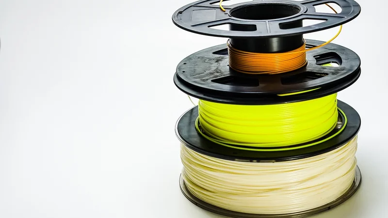
Additive manufacturing has moved from a niche prototyping tool to a standard part of the engineering workflow. Digital design and hardware engineers now use desktop fused filament fabrication (FFF/FDM) printers to produce parts like sensor brackets, PCB enclosures, jigs, and fixtures on demand. The convenience is clear, but consistent results require more than simply pressing print.
Unlike injection molded plastics, 3D printed polymers are anisotropic and sensitive to process conditions. Layer adhesion, print orientation, and thermal history all affect strength, introducing variability that engineers must account for. Mechanical performance therefore becomes a design variable rather than a given material constant.
This article explains the fundamentals of 3D printed polymer strength and includes a 3D printer filament strength chart comparing tensile and flexural properties of common materials, including popular thermoplastics and composite materials.
Fundamentals of Mechanical Strength in Fused Filament Fabrication
When engineers move from printing visual models to making parts that carry real loads, questions of strength quickly come to the foreground. With fused filament fabrication, mechanical performance is shaped not only by the polymer itself but also by how it is deposited, bonded, and oriented during printing. The following sections outline the key concepts that govern how printed parts behave under stress.
Stress–Strain Behavior
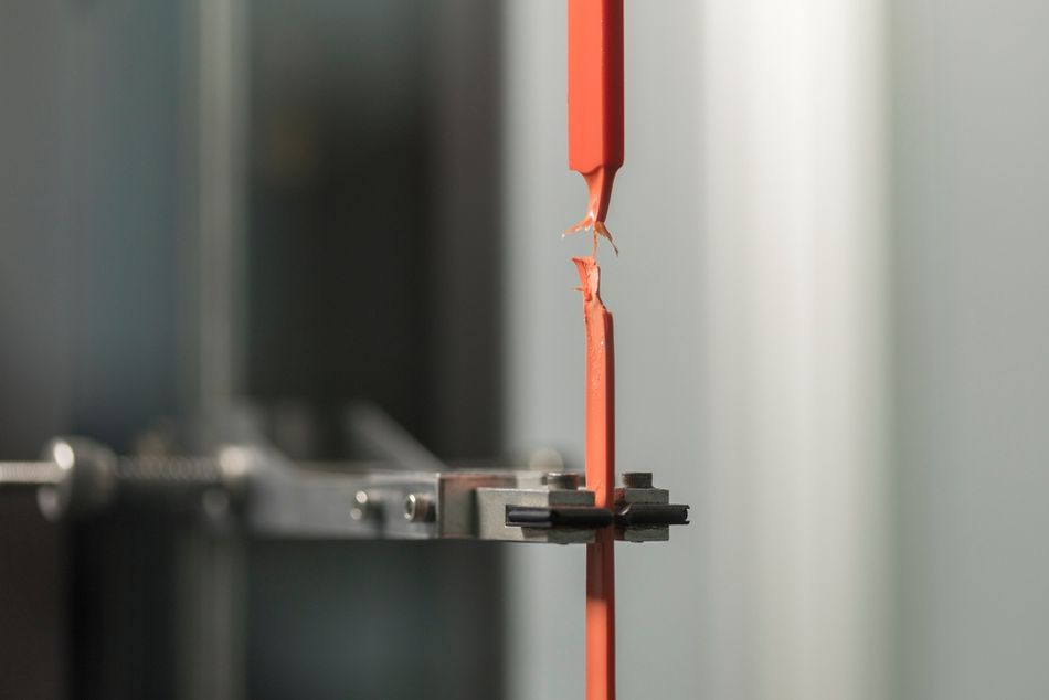
In a tensile test, a polymer specimen initially stretches in a predictable, elastic way. Stress and strain rise together, and the material returns to its original shape once the load is removed. At higher loads, the material reaches its yield point and begins to deform permanently. The yield strength marks this transition. As loading continues, stress increases until the specimen fractures. This maximum value is the ultimate tensile strength (UTS), which is higher than the yield strength. In most 3D printing discussions, “tensile strength” refers to UTS rather than yield strength.
Testing Standards and Units
To make strength data comparable, mechanical properties are measured using standardized test specimens and procedures. ASTM D638 and ISO 527 define the shape of the test samples, how they are gripped, the rate at which they are pulled, and the test environment.[1][2] Tensile and yield strengths are reported in megapascals (MPa) or pounds per square inch (psi). Other commonly cited metrics include flexural strength, which describes resistance to bending, and impact strength, which reflects how much energy a material can absorb before failing.
Material Microstructure and Anisotropy
FFF filaments are thermoplastics, but their internal structure varies. Semi-crystalline materials, such as nylon and PETG, contain ordered crystalline regions within an amorphous matrix, which can improve toughness and ductility. Amorphous polymers, including ABS and polycarbonate, lack these crystalline domains and tend to show more uniform, though sometimes lower, stiffness. Molecular weight and additives, such as fillers or plasticizers, further modify these properties.
The printing process itself introduces anisotropy. Strength within a printed layer, in the XY plane, is typically much higher than strength between layers along the Z axis, where bonding is less complete.[3] This difference makes part orientation a practical design decision. Loads are best carried along the plane of the layers rather than across them.
Yield vs Tensile Strength: Why Both Matter
Yield strength indicates whether a printed part will bend or creep under normal use, while tensile strength defines the point at which it will break. In practice, engineers aim to keep service stresses below the yield limit and apply safety factors well below the ultimate tensile strength. Considering both values provides a clearer picture of how a printed part will behave in real applications.
3D Printer Filament Strength Chart
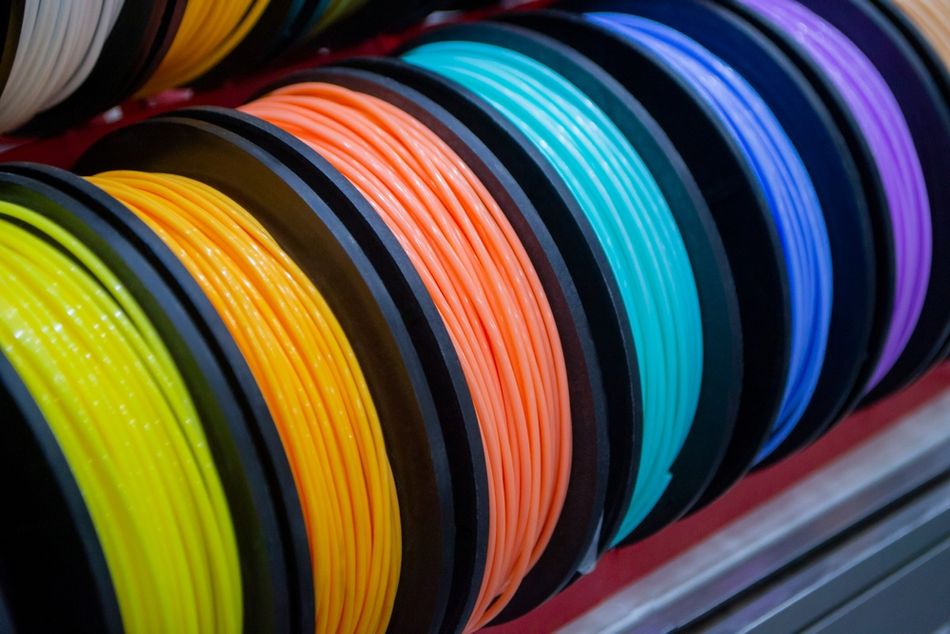
Selecting a filament for functional parts involves more than choosing what is easiest to print or most widely available. Strength, stiffness, and toughness vary widely across materials, and published datasheet values rarely reflect how parts behave once they are printed layer by layer. A clear comparison helps bridge the gap between material claims and real-world performance.
The 3D printer filament strength chart below brings together typical tensile strength, flexural strength, and impact resistance for common fused filament fabrication materials, from low-cost PLA through high-temperature engineering polymers such as PEKK and PEEK. The values are intended as practical reference points for printed parts, not idealized laboratory maxima, and they assume reasonable print quality and proper material handling.
Material | Tensile Strength (MPa) | Flexural Strength (MPa) | Impact Resistance | Relative Cost | Printability Notes |
PLA | ~55–65 | ~80–100 | Low | Low | Very easy to print; low warp; brittle under shock |
PLA Tough | ~50–60 | ~70–90 | Medium | Low | Improved ductility over PLA; limited heat resistance |
ABS | ~35–45 | ~60–75 | Medium–High | Low | Heated bed and enclosure recommended |
ASA | ~40–50 | ~65–85 | Medium–High | Medium | Similar to ABS; better UV stability |
PETG | ~45–55 | ~70–85 | Medium | Low | Heated bed; tough but notch-sensitive |
PET | ~50–60 | ~75–90 | Medium | Medium | Requires controlled cooling; stiffer than PETG |
HIPS | ~30–40 | ~55–70 | Medium | Low | Enclosure helpful; relatively impact tolerant |
PP (Polypropylene) | ~25–35 | ~45–60 | High | Medium | Difficult adhesion; excellent fatigue and impact behavior |
TPU (95A) | ~30–40 | ~60–80 | Very High | Medium | Flexible; slow speeds; direct drive preferred |
TPE | ~20–30 | ~40–60 | Very High | Medium | Extremely flexible; challenging extrusion control |
Nylon 6 (PA6) | ~50–70 | ~80–100 | High | Medium | Hygroscopic; heated bed and enclosure recommended |
Nylon 66 (PA66) | ~65–80 | ~90–120 | High | High | High print temps; moisture sensitive |
Nylon 12 (PA12) | ~45–55 | ~70–90 | Medium–High | High | Better dimensional stability than PA6/66 |
POM (Acetal) | ~60–70 | ~90–110 | Medium | High | Warping risk; enclosure required |
PMMA (Acrylic) | ~60–70 | ~90–110 | Low | Medium | Brittle; enclosure recommended |
PC (Polycarbonate) | ~60–70 | ~90–110 | High | High | High nozzle and bed temps; enclosure required |
PPS | ~70–90 | ~110–140 | Medium | Very High | Industrial printer required; excellent thermal stability |
PSU (Polysulfone) | ~65–75 | ~100–130 | Medium | Very High | High temp; controlled chamber mandatory |
PEKK | ~80–100 | ~120–150 | Medium | Very High | Industrial-grade temperatures and chamber |
PEEK | ~90–100 | ~140–170 | Medium | Very High | Extreme temperatures; heated chamber essential |
Other Material Selection Considerations
Before settling on a filament, it helps to consider factors that sit outside simple strength rankings. Printed parts often succeed or fail based on how materials behave in use, how difficult they are to process, and whether their cost is justified for the application.
Strength vs Ductility: Stiff materials like PLA resist deformation but fail abruptly. More ductile polymers, such as PETG and many nylons, tolerate flexing and are better suited to snap fits and compliant features.
Impact Behavior: Parts exposed to drops or sudden loads benefit from tougher materials. Polypropylene, TPU, and nylon absorb energy far better than brittle polymers, even if their tensile strength is lower.
Temperature Resistance: PLA softens at relatively low temperatures, limiting its use in warm environments. ABS, polycarbonate, and higher-end polymers maintain strength as temperatures rise.
Environmental Sensitivity: Moisture, UV exposure, and chemicals can degrade performance. Nylon absorbs water and must be dried, while ASA offers improved outdoor stability compared with ABS.
Processing Difficulty: PLA and PETG print with minimal setup. ABS, nylon, and polycarbonate often require heated beds and enclosures to control warping and layer adhesion.
Cost and Practicality: Low-cost filaments support rapid iteration. High-performance materials demand higher investment in both material and hardware, which should be justified by clear performance needs.
Composite Filament Strength Chart
Composite filaments are typically encountered as familiar base polymers modified with short, dispersed reinforcements rather than as entirely new materials. These additives are used to change stiffness, dimensional stability, thermal behavior, or surface finish, often at the expense of ductility and impact resistance.
The table below summarizes the most common composite filaments used in fused filament fabrication, focusing on how each reinforcement alters real-world print behavior and part performance.
Composite Filament | Base Polymer | Reinforcement Type | Mechanical Effect | Printability Notes |
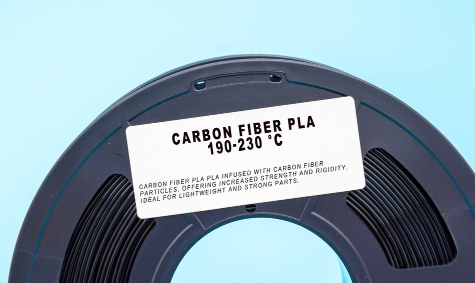
PLA-CF | PLA | Chopped carbon fiber | Higher stiffness; reduced creep | More brittle; hardened nozzle recommended |
PETG-CF | PETG | Chopped carbon fiber | Improved rigidity; better dimensional stability | Less stringing; abrasive |
ABS-GF | ABS | Chopped glass fiber | Improved toughness and heat resistance | Enclosure required; abrasive |
Nylon-CF | PA6 / PA12 | Chopped carbon fiber | High stiffness-to-weight; reduced warp | Moisture sensitive; abrasive |
Nylon-GF | PA6 / PA66 | Chopped glass fiber | Improved impact resistance and stability | Higher extrusion temps; abrasive |
PC-CF | Polycarbonate | Chopped carbon fiber | Very high stiffness and heat resistance | High temps; enclosure mandatory |
Factors Affecting Printed Part Strength
Printed part strength is ultimately a question of durability, not just headline numbers. In fused filament fabrication, the same 3D printing filament can produce parts with very different mechanical behavior depending on orientation, print settings, and thermal control. Understanding how these factors interact with underlying material properties is essential when comparing 3D printing materials for functional use.
Print Orientation and Anisotropy
Because parts are built layer by layer, strength depends strongly on direction. Loads applied parallel to the layers are carried along continuous extrusions, while loads applied in the Z direction must cross weaker interlayer bonds. This is why materials with high tensile strength on paper, such as polylactic acid, can still fail prematurely if oriented poorly. Engineers working with acrylonitrile butadiene styrene or polyethylene terephthalate glycol often prioritize orientation first, since interlayer bonding has more influence on real strength than the base filament properties alone.
Infill Density and Internal Structure
Infill controls how stress is distributed through the part. Higher infill densities and stronger lattice patterns improve stiffness and modulus, but they also increase print time and material use.[4] In many cases, strength gains come more efficiently from thicker outer walls than from filling the interior completely. This balance is central to any meaningful filament comparison, especially when durability rather than cosmetic finish is the goal.
Wall Thickness and Perimeters
Perimeters carry most of the load in tension and bending. Increasing wall count improves load sharing and reduces stress concentrations, particularly in brittle materials. For tougher, high impact filaments, added perimeters also improve resistance to crack propagation and abrasion at edges and fastener interfaces.
Layer Height, Temperature, and Adhesion
Layer height affects how well adjacent extrusions fuse, while printing temperatures control polymer flow and molecular diffusion. Higher extrusion and bed temperature generally improve interlayer adhesion, but excessive heat can reduce dimensional accuracy or degrade the material. Adhesion to the build surface also matters: techniques such as using a glue stick are common with ABS and PETG to prevent warping, indirectly improving final strength by maintaining proper geometry.
Printing Speed, Cooling, and the Extruder
Printing too fast limits bonding time between layers, reducing strength and elasticity. Cooling must be tuned carefully; aggressive fan use can weaken interlayer adhesion in materials like PETG or nylon. Extruder performance also plays a role, as inconsistent flow leads to voids that reduce wear resistant behavior and long-term durability.
Support Materials and Post-Processing
Support material choices can influence surface integrity. Soluble supports such as PVA improve compatibility with complex geometries but require careful moisture control and removal. Post-processing methods, including thermal annealing or chemical solvents, can alter material properties, sometimes increasing stiffness while reducing impact resistance.
Recommended reading: How Strong Are 3D Printed Parts? A Comprehensive Analysis
High-Performance Materials and Future Directions
As fused filament fabrication moves into production settings, progress is coming less from stronger base plastics and more from coordinated advances in materials, reinforcement methods, and printer capability. The focus has shifted toward predictable performance, thermal stability, and structural efficiency rather than headline strength alone.
Carbon Fiber Reinforcement and Hybrid Materials
Carbon fiber–reinforced filaments have evolved into engineered materials with controlled fiber length, surface treatment, and loading. Companies such as 3DXTECH offer carbon and glass fiber–filled grades based on nylon, PEKK, PEEK, and PEI, aimed at stiffness and dimensional stability rather than toughness. At the structural end, Markforged and similar vendors embed continuous fibers during printing, allowing strength and stiffness to be placed selectively along load paths instead of uniformly throughout a part.
High-Temperature and Engineering Polymers
Materials such as PEEK, PEKK, and PEI are becoming more practical as printer manufacturers improve chamber heating, temperature control, and support strategies. Suppliers like Filamentive and industrial OEMs now emphasize consistency, crystallization control, and process repeatability over marginal strength gains. This has expanded use cases into electrically insulating components, chemical environments, and parts exposed to long-term thermal cycling.
Recommended reading: PEEK 3D Printing: Unlocking the Potential of High-Performance Polymers
Structural Design and Algorithmic Geometry
Material advances increasingly work alongside structural optimization. Gyroid lattices, graded infill, and topology-optimized geometries are used to achieve high stiffness or high impact resistance with minimal material. When paired with fiber reinforcement or multi-material printing, these approaches enable lightweight parts with behavior closer to engineered structures than traditional plastics.
Hybrid and Post-Processed Materials
Bound metal and ceramic filaments extend FFF into sintered metals and wear resistant ceramics, with companies refining debinding and sintering workflows for better dimensional control. While distinct from polymer printing, these systems reflect a broader trend toward hybrid manufacturing, where printed geometry is only one stage in achieving final performance.
Conclusion
Mechanical strength defines whether a 3D printed part is merely a prototype or a functional component. Understanding yield versus ultimate tensile strength, and using a 3D printer filament strength chart to compare common and engineering-grade materials, helps frame realistic design limits. In practice, ductility, heat resistance, printability, and cost are often as important as raw strength.
Just as critical are process choices. Orientation, wall count, infill, temperature, and speed can transform the same material from fragile to robust, while high-performance filaments such as carbon fiber composites and PEEK extend the usable range of printed parts. With disciplined design and process control, fused filament fabrication can deliver reliable, load-bearing components rather than just convenient prints.
FAQ
What is the strongest 3D printer filament?
Among conventional FFF filaments, polycarbonate, fiber-reinforced nylons, and high-temperature polymers such as PEEK and PEKK are typically the strongest options available.
How does infill percentage affect strength?
Increasing infill reduces internal voids and generally increases strength. The largest improvements occur when moving from low to moderate infill; beyond roughly two-thirds solid, extra material tends to add weight and print time with diminishing returns.
Is PLA strong enough for functional parts?
PLA is stiff and reasonably strong in tension, but it is brittle and softens at relatively low temperatures. It works well for fixtures and lightly loaded parts, while PETG or ABS are better choices where impact resistance or heat tolerance is required.
Can 3D printed parts replace injection molded parts?
Printed parts can be competitive for low volumes, customized designs, or rapid iteration. Injection molding still offers more uniform strength, better surface finish, and superior economics for high-volume or heavily loaded components.
How can I ensure consistent strength across batches?
Consistency depends on controlling variables. Keep filament dry, use stable temperatures and speeds, maintain the same print orientation, and avoid frequent profile changes. Printing simple test coupons alongside parts can help confirm repeatability.
Why do printed parts sometimes fail at layer lines?
Layer lines are inherent weak points because bonding between layers is weaker than within a layer. Low extrusion temperature, aggressive cooling, or moisture in the filament can worsen this effect. Higher temperatures, slower prints, and enclosed build chambers usually improve layer bonding.
What are the future trends in FFF material strength?
Current development focuses on continuous fiber reinforcement, improved high-temperature polymers, multi-material printing, and optimized lattice structures. These advances are steadily expanding the range of load-bearing and industrial applications for filament-based printing.
References
[1] ASTM International. ASTM D638-14: Standard Test Method for Tensile Properties of Plastics. West Conshohocken (PA): ASTM International; 2014.
[2] International Organization for Standardization. ISO 527-1:2019: Plastics — Determination of tensile properties — Part 1: General principles. Geneva (CH): ISO; 2019.
[3] Zohdi N, Yang R. Material anisotropy in additively manufactured polymers and polymer composites: a review. Polymers. 2021 Sep 30;13(19):3368.
[4] Tanveer MQ, Mishra G, Mishra S, Sharma R. Effect of infill pattern and infill density on mechanical behaviour of FDM 3D printed Parts-a current review. Materials Today: Proceedings. 2022 Jan 1;62:100-8.