Keysight CAE-Manufacturing Suite-Assembly
Virtual Modeling of Assembly Sequences and Geometric Variation
General
| Product Type | Software |
| Applications | Prototyping & Development, Automotive Systems, 3D Printing & Manufacturing, Precision Mechanics |
| Key Features | Assembly Sequences, Geometric Variation, Virtual Simulation |
Technical Specifications
| Simulation Type | Process Level Virtual Assembly Simulation |
| Joining Operations | Prepositioning, Clamping, Spot Welding, and Release Sequences |
| Input Data | Simulation Data |
| Process Modeling | Sequential Part Positioning and Release |
| Distortion Prediction | Post-Assembly Deformation and Deviation Analysis |
| Workflow Integration | Connects with CAD, PLM, and Simulation Tools |
| User Interaction | Through the Graphical Environment or Excel |
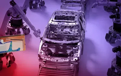
| Primary Application | Automotive Body-in-White Assembly Analysis |
Overview
Overview
Keysight Assembly is a process-level simulation tool engineered to replicate and validate physical joining and assembly workflows in a virtual environment, with particular emphasis on complex Body-in-White (BIW) automotive structures. The software models the sequence of part positioning, clamping, joining operations (e.g., spot welding), and subsequent release to assess resulting dimensional changes and distortions well before physical try-outs are available.
This enables engineers to quantify assembly outcomes, such as gap closures, residual stresses, and geometric deviations, under realistic process conditions by incorporating CAD data, scan inputs, and simulation data, as well as from the stamping process. It supports integration with existing PLM, CAD, and simulation ecosystems to maintain continuity across design, validation, and manufacturing planning. The workflow of this tool mirrors shop-floor logic, allowing users to construct and iterate assembly sequences visually without requiring any finite-element expertise.
Keysight Assembly - Simulation Software Features
Keysight Assembly is a process-level simulation environment focused on modeling joining, clamping, and sequencing effects on final assembly geometry and distortion. Let’s go through its features in detail:
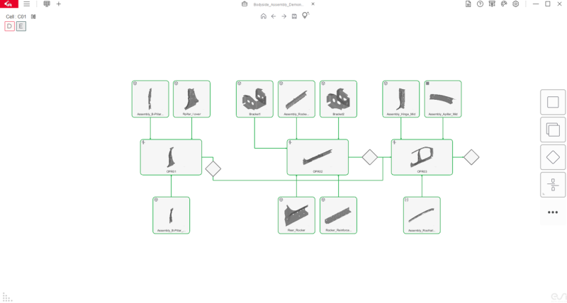
Process-Driven Workflow That Mirrors BIW Assembly Cells
Keysight Assembly is organized around the same sequence logic used on the shop floor: part positioning, clamping, spot-weld operations, and unclamping.
Users build assembly cells and process steps via a graphical, drag-and-drop workflow, and can define subassemblies that are reused downstream to reflect real line build-up behavior.
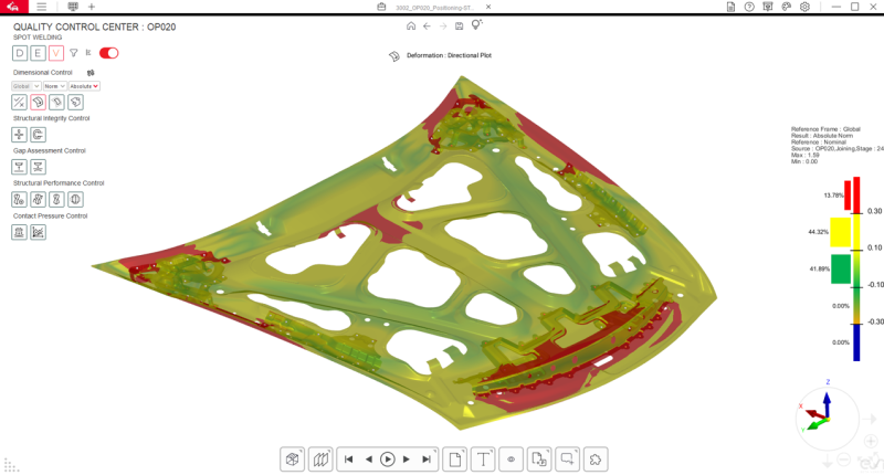
Distortion and Dimensional Accuracy Prediction
The software targets BIW distortion mechanisms that appear when gaps are forced closed by clamps, welds are applied, and stresses are released after unclamping, often pushing assemblies out of tolerance.
It includes an accurate solver for predicting geometrical distortions with short turnaround times, supporting early assessment of the final body geometry against dimensional targets.
Sequence Optimization for Clamping and Welding
Engineers can test alternative positioning strategies, clamping sequences, and weld orders/layouts, including spot welds executed one-by-one or in parallel (e.g., multiple weld robots). This supports virtual evaluation of process changes before physical try-outs and fixture modifications.
Data Continuity From Concept CAD to Scan-Based Validation
The same process model can be refined as inputs mature: nominal CAD for concept setups, simulation-based geometries for higher realism, and scanned part/subassembly data to validate against real shapes (useful when parts are outsourced). Besides this, some parts are taken over from one model to the next, so by scanning the previous (same) components, the accurate description of the final part geometry of that specific part can already be taken into account at the start of the engineering process. This reduces “rebuild-at-each-milestone” modeling and keeps the process definition consistent across phases.
Realistic Geometry Generation for Early-Phase Studies
Nominal CAD (CAD-0) represents a ‘perfect’ geometry, where no gaps appear during closing due to idealized conditions. To introduce realism, the tool generates manufactured shapes with deviations using part geometry, material type, and thickness as input. These non-nominal inputs replicate actual gap conditions during clamping, enabling more accurate prediction of stresses and distortions, and supporting process optimization and countermeasure development from the start of the project.
Built-In Tooling, QC Gates, and Domain Checks
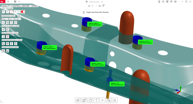
Tooling can be created directly in-app (e.g., clamps, locators, guides, supports) without external CAD, with commonly used geometries stored in a database. The workflow can insert quality control gates where the user can check distortions, stresses, and displacements after each assembly step.
The dedicated virtual QC cell can measure dimensional deviations, internal stresses, clamp forces, and component gaps before/after welding. Domain intelligence can flag rules such as spot-weld spacing and edge proximity.
References
Recommended Specs

Continue Reading
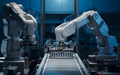
Automation on automotive assembly lines maximizes production quality and throughput.
Keysight Assembly is a process-level simulation environment focused on modeling joining, clamping, and sequencing effects on final assembly geometry and distortion.


Physics is about the web, rather than the spider.