Hybrid Mobile Robot Mechanism
A mechanically hybrid mobile robot.
Overview
The robot is has a combination of parallel and serially connected links which results in a hybrid mechanism that consists of a mobile robot platform for locomotion and a manipulator arm for manipulation.
Unlike most other mobile robot designs that have a separate manipulator arm module attached on top of the mobile platform, this design has the ability to simultaneously and interchangeably provide locomotion and manipulation capability.
Design
- Design and package the manipulator arm and the mobile platform as one entity rather than two separate mechanisms.
- Integrate the manipulator arm into the platform such that to eliminate its exposure to the surroundings.
- Nest all robot links and the end-effector into each other to allow complete symmetry of the platform’s geometry.
- Provide the ability to deploy/stow the manipulator arm from either side of the platform
- Integrate passive wheels into the robot joints in order to support the robot links when used for locomotion/traction.
- Integrate each link with a revolute joint and to be able to provide continuous 360 deg rotation.
- Attach rounded and pliable covers to the sides of the platform to prevent immobilization as well as to absorb some of the energy resulting from falling or flipping over of the robot.
- Embed interchangeable track tension and suspension mechanism in the mobile robot base links to form the locomotion subsystem of the robot.

**Figure 6. **Deployed-link configuration mode of the mobile robot.
The design includes two identical base link tracks left and right, Link 2, Link 3, passive wheels, and end-effector mechanism Fig. 6, Detail A. The two base links have identical orientations and they move together. This is achieved by fixing each of the base links to the ends of one common shaft. The common shaft is stationary and is located in Joint 1, as shown in Figs. 6 and 8.

**Figure 7. **Stowed-link configuration mode of the mobile robot „top/bottom covers removed.
To support the symmetric nature of the design, all links are integrated into the platform such that they are nested into one another. Link 2 is connected between the left and right base link tracks via Joint 1 and is rotating about the main common shaft. Passive wheels are inserted between Links 2 and 3 and connected via Joint 2 and another passive wheel is inserted between Link 3 and the end effector via Joint 3. The design also includes a built-in dual-operation track tension and suspension mechanism situated in each of the base link tracks.
Along with the challenge and effort to realize the concept into a feasible, simple, and robust design, most of the components considered in this design are off the shelf. The assembly views show the platform/chassis design and the different internal driving mechanisms along with the description of the components used and their function. The closed configuration of the robot Fig. 7—all links stowed is symmetric in all directions x, y, and z.
This design characteristic is extremely important for significantly enhancing locomotion ability. As shown in Fig. 7, rounded and pliable side covers are attached on the sides of the mobile robot to prevent immobilization when flipover occurs as well as to absorb some of the energy resulting from falling or flipping over events. Although the design is fully symmetric, for the purpose of explanation only, the location of Joint 1 will be taken as the reference point, and it will be called the front of the robot.
Motor Layout and Driving Mechanisms
The design includes four motors situated in the base links and two more in the space available in Link 3 for the gripper mechanism. Of the four motors located in the base links, two are situated at the back of each of the base links and the other two at the front Fig. 8. All four motors at the base link tracks are identical Brushless DC Motors BN34-25EU-02, available from Moog Components Group with a rated power of 363 W and a continuous stall torque of 0.7 N m.
The motor at the back of each base link provides propulsion to the track attached to that specific base link. The motion from each motor at the back is transmitted through a 1:32 ratio planetary servo gearhead Series E60, available from Textron Fluid & Power and a 1:2 ratio bevel gear in order to transfer the motion in a 90 deg angle as well as to amplify the torque capacity required for propelling the pulleys that drive the tracks.

**Figure 8. **Open configuration mode and general dimensions, front and top views—all covers removed.
Both motors at the back together provide the mobile robot translation and orientation in the plane of the platform. The motor at the front of each base link provides propulsion to one additional link. The motion is transmitted through a 1:120 ratio harmonic drive CSF20-120-2UH, available from Harmonic Drive Systems Inc. and two additional transmission stages, namely, a 1:2 ratio bevel transmission followed by a 1:2.5 ratio chain and sprocket transmission in order to achieve greater torque capacities as required for Links 2 and 3 Fig. 8.
The motor at the front of the right base link propels Link 2 and the motor at the front of the left base link propels Link 3 Figs. 6 and 8. Each of the motors is equipped with a spring applied break FSBR007, available from Inertia Dynamics as well as a miniature optical encoder E4 series, available from US Digital for position and velocity control purposes.
The overall location of the platform’s COG is an important characteristic that affects the robot’s tip-over stability. Therefore, the mechanical structure was derived such that motors and driving mechanisms for the tracks and all links are situated at the base to maintain the entire structure’s COG closer to the ground.

**Figure 9. **Isometric view of base link track showing internal pulley arrangement.
The gripper mechanism along with its associated electronics and independent power sources are situated in the space available in Link 3. For the existing design, the gripper has two DOFs and
hence two additional motors and gear systems. As for Links 2 and 3, the gripper submechanism is integrated such that it can provide continuous rotations about Joint 3 Fig. 6, Detail A and hence can
be deployed from either side of Link 3.
Rotation about Joint 3 is generated with a DC Micromotor Series 3557-012C, available from Faulhaber Group with an output power of 14.5 W and a continuous stall torque of 115 mN m, connected to a 1:246 ratio planetary gearhead Series 38/2, available from Faulhaber Group and a 1:3 ratio bevel gear.
The open/close motion of the gripper is implemented with a flat brushless DC motor EC45, available from Maxon Motor with an output power of 12 W and a nominal torque of 22.8 mN m connected to a miniature 1:100 ratio Harmonic Drive CSF-Mini Series Type 2XH-J, available from Harmonic Drive Systems Inc. and a 1:30 ratio worm gear Fig. 8.
Other accessories typically found in mobile robots such as cameras, lights, and antennas are embedded in the platform. In other designs of mobile robots, these items typically stick out or protrude from the platform. In order to prevent their exposure to the surrounding and thereby eliminate risk of damage in cases were the robot flips over or falls, the charge-coupled device CCD cameras and light-emitting diode LED lights were embedded in the front and back of the left and right base link tracks, respectively, as shown in Fig. 7 and the top view in Fig. 8.
Two special flat antennas are embedded in the right and left side covers for Data RF signals and Audio/Video RF signals, respectively Fig. 7. The flat shape of the antennas and their location in the side covers maintain the symmetric nature of the entire hybrid platform and minimize the chance for loss of data or breakage of the antenna if it were to protrude vertically up.
Built-In Dual-Operation Track Tension and Suspension Mechanism
The arrangement of the supporting planetary pulleys is shown in Fig. 9. Each of the supporting pulleys is mounted on a supporting bar Fig. 9 that is connected at each end to a compression spring Fig. 6, Detail B. The ends of each supporting bar are guided through a groove on either side of the base link as shown in Detail B of Fig. 6.
Therefore, each set of three planetary pulleys in the top and bottom of the left and right base link tracks is suspended by a 23 spring array. The purpose of the supporting pulleys is dual and provides two very important functions. While the bottom three supporting pulleys in each base link are in contact with the ground, they act as a suspension system.

**Figure 10. **Side view of base link track showing general pulley arrangement and track tension/suspension mechanism.
At the same time, the upper three supporting pulleys will provide a predetermined tension in the tracking system, as shown in Fig. 10. This dual operation track suspension and tension mechanism accounts for the symmetric nature of the design and operation of the mobile robot. In other words, if the platform is inverted, the three supporting pulleys that were used as suspension will act to maintain the tension in the tracks, while the other three pulleys that were used to provide tension in the tracks will act as a suspension system.

**Table 1. **Robot design specifications.
The required tension in the track belt and the suspension stroke can be preset by fastening or loosening the compression nuts Fig. 6, Detail B. Another usage of the spring array is to absorb some energy resulting from falling or flipping, thus providing compliance to impact forces. General design specifications of the robot are provided in Table 1. Photos of the hybrid mobile robot physical prototype in the close and open configurations are shown in Figs. 11a and 11b. In order to support the reported mobility of this robot, a photo showing the prototype in the configuration illustrated in Fig. 13a is shown in Fig. 11c.
Robot Degrees of Freedom Coordination
The remote operating control unit OCU includes two control sticks in order to coordinate the robot degrees of freedom when generating the motions required for a given task. Of the four motors located in the base links, two are situated at the back of each of the base links and the other two at the front Fig. 8. The motor at the back of each base link provides propulsion to the track attached to that specific base link. Both motors at the back together provide the mobile robot translation and orientation in the plane of the platform. The motor at the front of the right base link propels Link 2 and the motor at the front of the left base link propels Link 3 Figs. 6 and 8.

**Figure 11. **A photo of the physical prototype: „a… stowed-link configuration mode, „b… open configuration mode, and „c… and „d… cylinder climbing configuration.
For the existing design, the gripper mechanism has two DOFs and hence two additional motors are located in the system. The forward, backward, right turn, and left turn motions of the base link tracks are controlled by up, down, right, and left movements of the first control stick. The second control stick is used to control Links 2 and 3 degrees of freedom. A right movement of this control stick will generate a clockwise CW independent motion of Link 2 while a left movement of the stick will generate a counterclockwise CCW independent motion of Link 2.
Specifications
- Total estimated weight including batteries and electronics: 65 kg
- Length arm stowed: 814 mm
- Length arm deployed: 2034 mm
- Width with pliable side covers: 626 mm
- Height arm stowed: 179 mm
References
Provides a brief background to the field of mobile robots along with examples of existing types of design architectures. Introduces a conceptual function-oriented analysis that outlines a summary of existing issues related to tracked mobile robots. Describes the design resulting from the analysis of
Elaborate dissertation which provides a detailed mechanical design and outlines the development of a new systematic approach for a modular control architecture. The experimental setup and results that corroborate the hypothesis of this work are discussed and the conclusions presented.
Recommended Specs


Continue Reading
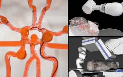
The system could provide teleoperated endovascular treatment to patients during the critical time window after a stroke begins.

In this episode, we talk about how ostriches are inspiring a new generation of bipedal robots and the innovation enabling remote endovascular surgery.


Humans excel at manual tasks, and ideally, robots should surpass us in these functions. We have the advantage due to our superior dexterity, and we can perform tasks that robots should, in theory, be capable of. As we advance robotics our goal is to effectively transfer our human skills to robots.

6 minutes read