AILA Robot
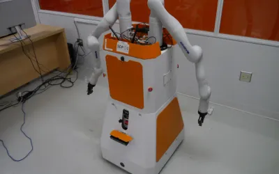
A mobile dual-arm robot developed as a research platform for investigating mobile manipulation. The robot AILA integrates and allows in a single platform to perform research in most of the areas involved in these field of autonomous robotics: navigation, mobile and dual-arm manipulation planning, active compliance and force control strategies, object recognition, scene representation, and semantic perception.
Overview
The robot AILA integrates and allows in a single platform to perform research in most of the areas involved in these field of autonomous robotics: navigation, mobile and dual-arm manipulation planning, active compliance and force control strategies, object recognition, scene representation, and semantic perception.
AILA has 32 degrees of freedom, including 7-DOF arms, 4-DOF torso, 2-DOF head, and a mobile base equipped with six wheels, each of them with two degrees of freedom. The primary design goal was to achieve a lightweight arm construction with a payload-to-weight ratio greater than one. Besides, an adjustable body should sustain the dual-arm system providing an extended workspace. Mobility is currently provided by means of a wheel-based mobile base.
Design
AILA consists of an anthropomorphic upper body mounted on a wheeled mobile platform. The upper body carries two arms, each of them with seven degrees of freedom, a torso with four joints, and a head with two degrees of freedom.
The mobile platform (Fig. 5) consists of six wheels with two degrees of freedom each, one for the steering axis and one for driving the wheel. The main focus of the design was on the development of the arms and the upper torso, being the mobile base a first solution to provide with mobility to the robot. Future developments will concentrate on new concepts of mobility/locomotion.
**Figure 5. **Wheeled mobile base used to provide mobility to the first platform. Future developments will focus on new concepts of mobility/locomotion for AILA.
The robot's hardware includes two Prosilica GC780C cameras that create a stereo system unit in the head which is mounted on a neck able to pan and tilt on an anthropomorphic path. A periodically-tilting short-ranged Hokuyo URG Laser scanner in the chest and a Mesa SR-4000 3D Time of Flight (TOF) camera in the robot’s stomach are combined for object and scene recognition, as well as for pose estimation.
Two long-ranging Hokuyo UTM Laser scanners provide circumferential view for the mobile base. These six different visual systems allow to extract a multi modal view of the environment. AILA is equipped with three computers. Two 3,5-inches embedded PCs: one for motion control located in the head and one for navigation located in the mobile base.A mini-ITX board in combination with a dedicated graphics card for vision processing is located in the torso.
The communication network consists of five independent CAN-lines for controlling the two arms, the torso, and the wheel modules of the base. Giga Ethernet routed through two five-port switches connect the head cameras, the three computers,and the outside world.
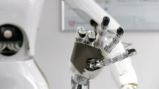
The motion computer communicates through a dedicated RS-485 bus with the Skyetek M4 RFID module which is integrated together with its antenna in the left hand. Further external sensors are two six-axis force-torque sensors at the robot’s wrists. Proprioceptive sensors include the hall-sensors for the measurement of the absolute position of the joints, motor current measurements, and incremental optical encoders for the motor commutation and joint torque measurement.
Mechanics
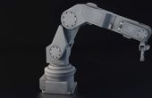
For the design of the arms, a kinematic model of seven degrees of freedom was chosen with pair-wise grouping of joints with intersecting axes at the wrist, and three intersecting axes at the shoulder (Fig. 2, Top).
The grouping of joints lowers the weight of their combined housing and helps to reduce the moment of inertia of the limb by placing the relatively heavy motors near to the arm’s base. The joints of the elbow and shoulder consist of brushless DC motors in combination with harmonic drives and are independently controlled by a stack of three PCBs housing power and control electronics.
**Figure 2. **Top: Arm specification. Bottom: Detail of the elbow housing containing two joints.
The two degrees of freedom of the wrist are controlled by a parallel kinematic structure driven by two DC linear motors, each of them including planetary gear, encoder, and its own controller. The assembly of two joints in one housing (Fig. 2, Bottom) is connected to the upper and lower arm structure by four-point thin-section bearings.
Specifications
- Two Prosilica GC780C cameras that create a stereo system unit in the head.
- A periodically-tilting short-ranged Hokuyo URG Laser scanner in the chest and a Mesa SR-4000 3D Time of Flight (TOF) camera in the robot’s belly.
- Two long-ranging Hokuyo UTM Laser scanners provide a circumferential view for the mobile base.
- Two 3,5-inches embedded PCs: one for motion control located in the head and one for navigation located in the mobile base.
- A mini-ITX board in combination with a dedicated graphics card for vision processing is located in the torso.
- The communication network consists of five independent CAN lines for controlling the two arms, the torso, and the wheel modules of the base.
- GigaEthernet routed through two fiveport switches connect the head cameras, the three computers, and the outside world.
- Two six-axis force/torque sensors at the robot’s wrists.
- In-house developed joint electronics consisting of a stack of three PCBs (power electronics, FPGA, interfaces and sensors).
References
Provide an overview of the design, especially in the mechatronics area, as well as of its realization, the sensors incorporated in the system, and its control software.
Selected steps out of its design process are discussed, as well as the requirements to develop the system. This paper outlines an approach to increase the efficiency of engineering design in the field of robotics by analyzing the bilateral influence of the system concept with embodiment design drive
Provides an overview of the mechatronics design, the variety of sensors incorporated in the system, and its required control software.
Recommended Specs

Continue Reading

This guide delves into the basics and components of PID control, implementation, application examples, impacts, challenges, and solutions aiming to provide readers with a thorough understanding of this integral concept.

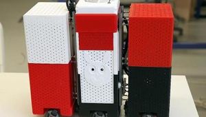
Rosie is a dual arm mobile manipulation robot designed for pick and place in an industry 4.0 setting.

8 minutes read
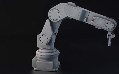
Ever wondered how robotic arms achieve precise movement in manufacturing, healthcare, or logistics? It’s all about smart design — from sturdy components and kinematics to advanced control systems. Discover how these elements work together to deliver accuracy, flexibility, and real-world efficiency.