sTetro
A modular, reconfigurable, and autonomous staircase cleaning robot.
Overview
The sTetro uses a vertical conveyor belt mechanism and is capable of navigating over flat surfaces (e.g., floor) as well as climbing staircases, thus significantly extending the cleaning capabilities of home cleaning robots. The working principle concept of sTetro is borrowed from the Tetris Tiling Theory. The sTetro's body consists of three cuboids connected with two sliders attached to each side of the central cuboid.
Design
The sTetro robot consists of six DC motors; among them, four (M1–M4) are Worm Gear DC motors, and two (M5, M6) are Pololu DC motor. It also has four high torque servo motors (Herkulex 0201: SM1 to SM4). The motors M1 to M4 operate at 11.1 V and draw an average current of 800 mA with power rating 1600 mAh to deliver a nominal torque of 3 kg cm. The Pololu DC motor (M5, M6) has more torque of about 14.5 kg cm and has a gear ratio of 172 : 1. Four Omni-directional wheels are used in sTetro, with a diameter of 48 mm, to navigate the robot in planar directions (X, Y plane).
Two of these Omni wheels (forward wheel) are driven by Pololu motors (M5, M6), and the side Omni wheels are driven by Worm Gear motors (M2, M3). In the 1st and 3rd blocks, DC motors M1 and M4 are installed to control the motion of monowheels (H-wheels), and Herkulex servo motors, SM3 and SM4, are used to control the direction of the 1st and 3rd block mono wheels. At the 2nd block, two servo motors (Herkulex: SM1, SM2) are attached to lift all three blocks using a vertical conveyor belt mechanism. Six long bump sensors are attached on the left/right sides of the robot to detect side boundaries of the stair, and two time of flight (ToF) sensors are attached on the bottom of block-1 and block-2 to detect touch down on tread. A 3rd ToF sensor is attached in front of block-3 to detect front riser touching during reconfiguration.
Locomotion
The sequence of sensing and control actions enables the sTetro robot to reconfigure itself and move forward, left/right wards and upwards. In the previous prototype, motion and reconfiguration actions were controlled by a human operator by sending control commands through a remote control, but in the current version, we have automated most of these actions. Different sensors are installed to accomplish the self-reconfiguration and locomotion task.
To make the locomotion and self-reconfiguration of sTetro automatic, simple, low-cost, low-weight, and power-efficient sensors have been used in this project. As it is a slow-moving wheeled robot to physically interact/negotiate with its environment (e.g., walls/stairs and human), the contact sensors are used in the design due to the robot’s slow motion and low momentum. Moreover, physical contact sensors are unaffected with environmental conditions, for example, light conditions and target material type, and are more accurate than electronic sensors. Contact sensors react only when they have physical touch with the surrounding environment and have a zero limiting range.
Six long bump sensors (BM1~6) are installed on the left and right sides of the robot to detect the side boundaries of the staircase. A contact switch (SW0) is installed in the front of block-1. Two touch sensors (SW2 and SW3) of the SPDT type are fixed on the front face of block-2 to detect the front riser and smooth sliding motion against the front riser. Two ToF1 and ToF2 sensors are fixed in the bottom of each block-1 and block-2 to detect the touchdown of these blocks on the tread of the stair. The third ToF3 sensor is attached in the front of block-3 to detect the front riser.
Misalignment Correction Technique
During operation, the sTetro robot must be aligned with the staircase riser so that it can cover all tread area for cleaning purposes. If some misalignment occurs uncorrected, the robot may fall back from the narrow tread’s area. In order to detect misalignment with the front riser, an attitude and heading reference system (AHRS) has been used in this work.
The AHRS consists of inertial IMU sensor (3 × gyros, 3 × accelerometers) on three orthogonal axes that provide attitude information (roll, pitch, and yaw/heading) for any moving platform on which the sensor is installed. When the robot touches the riser in the first step and is aligned with the staircase, the yaw angle at that position is taken as the reference heading, and any subsequent changes from this reference heading angle are taken as misalignments (with some tolerance/threshold). The AHRS algorithm is able to detect such misalignments very reliably and gives feedback to the control system for corrective measures.
Specifications
- Fully autonomous operation
- Enhanced cleaning time and larger area covered
- Visual components for stair and surface recognition
- Omni wheels for improved maneuverability
References
Recommended Specs

Continue Reading
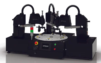
In the ever-evolving landscape of manufacturing and automation, efficiency and precision are paramount. Autoblocks™ understands this fundamental need and has introduced the groundbreaking Turn Block™ indexing table, a game-changer in the world of industrial automation.

2 minutes read

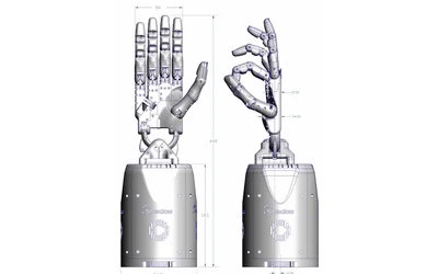
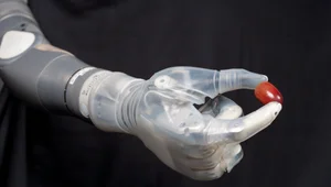
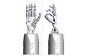
Part 2 of our dexterous robotic hand series.
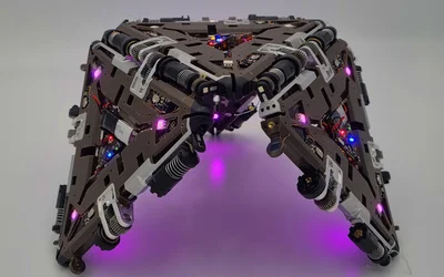
EPFL roboticists have shown that when a modular robot shares power, sensing, and communication resources among its individual units, it is significantly more resistant to failure than traditional robotic systems, where the breakdown of one element often means a loss of functionality.

3 minutes read