120-GHz Wideband IQ Receiver
A 120-GHz wideband I/Q receiver based on Baseband Equalizing Technique
Technical Specifications
| Transmitter | Power amplifier (PA): 9-dB back-off region |
| Simulated EVM: less than −30 dB from 69 to 140 GHz | |
| Receiver | Input power: −32 dBm |
| SNDR level: 19.8 dB | |
| NF: 11.75 dB | |
| Operating point of baseband amplifier: at least at 7-dB back-off | |
| Low Noise Amplifier | fLLNA: 105 GHz (1st, 5th, and 6th) |
| fHLNA: 135 GHz (1st, 5th, and 6th) | |
| Bypass capacitors with different capacitance values: 148, 204, 274, and 344 fF | |
| 3-dB conversion gain bandwidth | 26 GHz |
| Noise figure (NF) | 10.8 dB |
| DC power consumption | 153.4 mW |
| Maximum data-rate | BPSK: 12.5 Gb/s |
| QPSK: 16 Gb/s | |
| 16-QAM: 16 Gb/s | |
| Conversion gain | High gain mode: 28.2 dB |
| Low gain mode: 14.8 dB | |
| Receiver Chip area | 1.5 mm2 |
Overview
This tech spec was submitted by Taehwan Jang as part of the University Technology Exposure Program.
Problem / Solution
The use of millimeter-wave (mm-wave) and sub-terahertz spectrum in wireless connectivity systems has rapidly evolved over the years. As the frequency band integrates wideband unlicensed spectrum, facilitating fast data rates in short-range high-speed communication, demand for applications above 100GHz is also increasing. Thus, the need for a wide bandwidth in the utilization of the full potential of the mm-wave link. This system is mostly fabricated via a deep-scaled complementary metal oxide semiconductor (CMOS). The limitation in cutoff frequency for CMOS transceiver technology prompts challenges in bandwidth extension for mm-wave systems.
Using a baseband equalizing amplifier, a 120-GHz wideband I/Q receiver is observed through a 40nm CMOS technique. The receiver chipset integrates a direct conversion structure for low-power operation. A frequency equalizing technique allows for high data-rate wireless communication, placed between the low noise amplifier (LNA)-mixer and the baseband amplifier. In attaining a wider bandwidth along with a peak 6-dB gain, the amplifier boards third-order feedback on top of its inductive peaking technique. The technique lodges a bandwidth increase of as wide as 5 GHz, methodically increasing the overall gain of the system at a minimum gain loss.
Design
Receiver Architecture
Using the 40nm CMOS process, both the transmitter and receiver demonstrate a direct conversion structure. The power amplifier operating at a 9-dB back-off region ensures there is enough linearity performance in the transmitting signal, indicating results of less than -30dB from 69 to 140 GHz. For 3 cm distances, a path loss of 44dB and an antenna gain of 6 dBi result in an input power of -32dBm in the receiver.The required noise configuration for maintaining the ratio of the output signal to noise and distortion is 11.75dB, which will maintain a level of 19.8dB for 16 QAM signals. Setting the amplifier to a minimum of 7dB from the P1 dB will ensure the linearity of the receiver. To prevent saturation, a gain variation stage is added, which will also reduce DC power consumption.
In the direct conversion receiver, four parts include LNA, QILT, I/Q mixer, and the said baseband amplifier. The LNA reduces the NF of the receiver. The mixer down-converts the low noise signal from the LNA before allowing the QILT to generate four times the LO signal, which is the in-phase and quadrature mixer process. The baseband amplifier, as discussed, amplifies the I/Q signals. This receiver design covers a 105 to 135 GHz range for broadband data transmission. The condition requires at least 7, 10, and 17dB of SNR for 10-3 BER BPSK, QPSK, and 16-QAM modulation, while for 10-6 BER modulation, 9, 12, and 20dB are required.
Bandwidth Requirement of LNA, Down-Mixer, and Baseband Amplifier for the Bandwidth Expansion Technique
It is likewise necessary that the characteristics of the overall gain in the LNA-mixer be symmetric at the center of the frequency distribution as the gain of the amplifier mixed with the output cascades over an extended overall bandwidth. If not symmetric, the signal experiences a gain fluctuation of more than 3dB. Setting the peak frequency to 13 GHz will set the 6 dB peak gain to compensate for the rolling-off, thereby reassuring the bandwidth broadening. Even though high frequencies like this cause rapid loss in gain, the system exhibits a 3dB gain bandwidth of 28GHz.
Low-Noise Amplifier
In the LNA, a six-stage source amplifier minimizes the loss using only a single inductor, where a staggering tuning technique increases the 3dB gain of the amplifier. On the other hand, a bypass capacitor between the VDD and GND eliminates the AC ripple and noise, resulting in a stable LNA. Given this, the VDD line and matching inductor correspond to the AC ground node. However, over-cascading results in a long VDD line, causing parasitic impedances at the nodes—thereby using multiple capacitors with varying values to have an AC ground that caters to frequency values from 20–200GHz.
Down-Conversion Mixer
To down-convert the RF signal for higher conversion gain, the down-conversion mixer has a double-balance design that increases the IP2 in the design. The presence of an inductor in each node of the NMOS drain and gate will then neutralize parasitic capacitances under high gain. A current-bleeding stage further improves the conversion gain by inserting it at the common transistor gates to the transconductance stage drain. In order to measure the conversion gain, the mixer assumes that a -10dBM LO signal is sent into each quadrature port.
Baseband Amplifier With Equalizing Function
Meanwhile, the baseband amplifier amplifies the demodulated signal coming from the mixer without compromising the high-gained bandwidth at low power dissipation. A monotonically increasing gain slope ensures the desired 6dB peaking, together with the inductor peaking technique and active feedback topology approach. Two more techniques, such as offset cancellation circuits and current steering, are employed to prevent amplifier saturation and control the variable gain. Lastly, the output buffer will have a differential pair and an active load topology meant for single-ended measuring.
Quadrature Injection Locked Tripler Chain
The injection-locked frequency multiplier is commonly used to generate high-power signals efficiently at low noise. In this device, the QILT chain has an injection-locked oscillator (ILO), an ILFT (injection-locked tripler), a quadrature hybrid coupler, and an output ILO buffer. The two wideband hybrid couplers guarantee optimum quadrature signal since passive types may cause wide operational bandwidth with low amplitude and phase differentials. The design also allows for layout size reduction to only a 50 × 60 μm2 chip area.
Antenna
For the antenna, a Vivaldi model grants high gain compensation for path loss. It also provides wide bandwidth as targeted for operation. Its low profile is also within the short-length bond of a 300-μm-radio-frequency integrated circuit.
Results
The overall bandwidth gain at 3dB is 26 GHz, with NF at 10.8dB and consumption at 153.4 mW. The device supports a data rate of 16 gb/s for BPSK (binary phase shift keying), and in dual-mode operation, the conversion for the high gain mode is 28.2dB while the low gain registers at 14.8dB. The receiver tallies a max rate of 12.5 Gb/s for BPSK, 16 for QPSK (quadrature phase shift keying), and also 16 for 16-QAM (quadrature amplitude modulation).
References
A research paper describing the challenge, design, and outcome of the research.
Recommended Specs


Continue Reading

U-turns and left turns are sometimes forbidden even though it increases travel distances. We demonstrate through simulations that in comparison with conventional schemes, the ZTC road network can carry approximately 50% more vehicular traffic without incurring gridlock.

At the Delft University of Technology, a series of “self-propelling” needles have been developed for downsizing the diameter of tissue transportation systems.
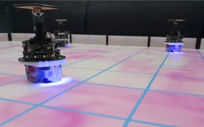
Researchers developed a system to conduct experiments in swarm robots that enables the e-puck robots to release and detect artificial pheromone to mimic stigmergic mechanisms.