The electrified car's powertrain explained
An illustrated deep dive into hybrid electric vehicle's architecture, system requirements, what that means for power semiconductors.

Last updated on 05 Aug, 2020. 14 minutes read
Image: Goceris
This article was originally written as a series of blog posts by Ian Kennedy and has been edited and formatted by Wevolver.
Electrification of the powertrain – introduction
Vehicle electrification has recently started to pick up aggressive speed in the automotive industry. The main drivers of this phenomena appear to be based around clean driving, decarbonisation, air quality and health in the urban environment. Often implemented through emission reduction requirements agreed locally or between governments and relevant organisations across the globe, these regulations require a quick response by the automotive OEMs to reduce the carbon footprint of their vehicles and avoid potentially heavy penalties.
The fundamental change is away from reliance on the conventional internal combustion engine (ICE) to some form of electrical powertrain. Multiple powertrain solutions are being implemented respective to the separate OEMs’ strategies, visions and financial capabilities. This has led to a plethora of new terminology within the industry. At first glance it can be bewildering, especially as new energy vehicles start to hit the roads in greater numbers. The most popular powertrain solutions being mentioned are: 48V mild hybrid (MHEV); full-hybrid (HEV); plug-in hybrid (PHEV); battery electric (BEV); and fuel cell (FCV).

Each one of these types has a specific architecture as well as individual operational and power requirements. Furthermore, the achieved carbon dioxide (CO2) reduction differs vastly, ranging from approximately 15% for 48V MHEVs to 100% for BEVs and FCVs.
These details need to be carefully considered and analysed by the automotive tier 1s, who directly supply the OEMs with the relevant automotive systems and parts (DC/DC converter, battery management system (BMS), inverter, etc.).
Among the key questions that all players in this industry would love to have the answer to, is which vehicle / powertrain type(s) will be the most dominant (both short term and long term) and when will the tipping point arrive for mass adoption. This is essential to develop a successful strategy and increase market share in the business.
In a nutshell, while solutions such as 48V MHEV and HEV are currently acceptable, long term they cannot offer a satisfying CO2 reduction and driver experience. Inversely, these partially electrified vehicles are relatively cost-effective to develop as they are close to the well-known conventional vehicle making it easy for OEM’s to implement within their existing manufacturing base. A simple evolutionary step.
End-game vehicle solutions such as BEVs and FCVs can solve the CO2 emission drama (at least in terms of vehicle emissions) while also providing customers with an entirely new driving experience (e.g. instant torque (BEV), autonomous driving functions, etc.). The main challenge for those vehicles is the high cost of production – battery cost (BEV), production of hydrogen (FCV), etc. – and manufacturing capacity to supply the millions of batteries needed for mass adoption. Furthermore, there are external challenges such as the charging infrastructure and power distribution which need further development to meet vehicle demand for electricity and allay consumers fears.
The appearance of 48V Mild hybrid
So how do MHEVs differ from a traditional ICE vehicle. In this section we dig into some of the key differences in terms of architecture.
The days of the internal combustion engine (ICE) are numbered. Well certainly you can be forgiven for thinking that given the number of major cities and even some countries talking about banning all diesel and petrol automobiles within the next 15-20 years. But hang on, is it really that easy to swap every vehicle with an electric equivalent? Of course, not. If it was, everyone would already be driving a fancy Tesla and hoping we don’t collide with a pedestrian or cyclist because of its extremely quiet electric motors.
Jokes aside, there are many challenges impeding the faster spread of electric vehicles (EV). From vehicle cost, charging infrastructure, power generation demand and range anxiety, to consumer behavior and attitudes to the new technology along with legal and insurance concerns. While these issues may take a decade or two to be fully sorted out, the regulations being imposed to curb carbon dioxide (CO2) emission are forcing vehicle manufacturers to come up with alternative, cost-effective, pragmatic solutions.
Mild hybrids (MHEV) and full hybrids (HEV) are stepping stones towards full vehicle electrification. This is mainly due to the high battery costs in full electric vehicles and the time pressure imposed on manufacturers. While batteries are gradually getting cheaper (80% lower costs between 2008-2018 according to the US Department of Energy) mass market EVs are not the short-term solution that CO2 regulation institutions are looking for, especially in Europe and China.
How MHEVs differ from ICE vehicles
So how do MHEVs differ from a traditional ICE vehicle? To start Figure 2 highlights the main system changes applied in an MHEV. The most obvious difference between a conventional vehicle and the mild hybrid is the addition of a 48-volt battery.
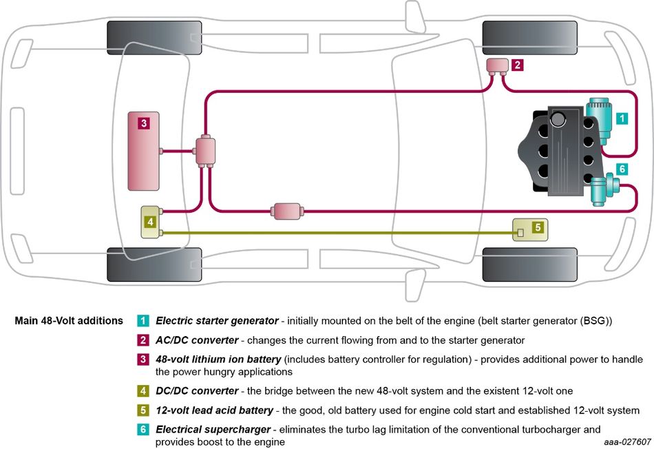
The main purpose of the 48-volt battery is to provide the additional power demanded by power-hungry applications as well as reducing the electrical current throughout the system. This trick allows for smaller cable cross-sections to be used, massively cutting the amount of copper in the 4+ kilometers of wiring in today's high-end vehicles. And therefore enabling significant weight and cost reductions. Other notable differentiating factors of mild hybrid are the new 48-volt modules such as the electric starter generator, electrical supercharger and DC/DC converter. The latter simply converts the 48-volt battery power to support established 12-volt applications in the vehicle.
Starter generators and superchargers
The 10 kW (or higher) starter generator is a very valuable 48-volt system addition and offers multiple functions. Firstly, it acts as an alternator (converting mechanical energy into electrical) and is connected to the crankshaft of the engine. Secondly, it boosts the engine to increase the vehicle’s acceleration performance and manages engine load to reduce fuel consumption. Lastly, when the vehicle is cruising or decelerating/stopping the starter generator can recover electrical energy back to the battery. Currently there are a few different architecture topologies, each of which provide a certain level of CO2 benefits.
Looking somewhat like the shell of a snail, the other main 48-volt addition is the electric supercharger. Its primary purpose is to increase the air/fuel mixture density that goes into the cylinder of the engine. Thus, more power is output from the engine without increasing cylinder size. With this capability, the supercharger effectively contributes to the fuel economy of the mild hybrid.
What to do with all that energy
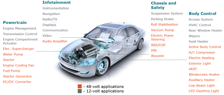
Of course, all this extra power still needs to be used efficiently, and not all vehicle systems need to be powered with 48-volts. From a pure power perspective, high power applications such as the starter generator, supercharger, DC/DC converter and A/C compressor would be the first to be ported across to the 48-volt supply network.
Figure 3 below shows which applications have the potential to transition to the higher voltage side.
The 48-volt starter generator
In this third section we try to understand firstly the reasoning behind the new 48-volt vehicle architecture and then delve into one of its main applications – the 48-volt starter generator, and look at some of the different mounting options for them.
An obvious initial question is: “But why exactly 48-volt?”. This is an important question, bearing in mind that in the late 1990s a 42-volt electrical power standard was proposed to replace the 12-volt standard. Although it did not gain momentum, it’s purpose was to address some of the same issues we face today, such as more powerful electrically-driven accessories and lighter wiring harnesses. However, there are two main reasons for selecting 48-volts as the nominal value – safety and efficiency.
A major concern when increasing voltage is the potential safety hazard it may impose on us humans. While some continue to debate whether 48-volt is safe enough, this voltage level provides the additional power required without drifting into the ‘high-voltage’ domain. Figure 4 shows the different voltage levels of operation for the 48-volt battery. The limit of 60-volts (DC) is the upper safety maximum before the battery voltage is considered too dangerous – as mentioned in ZVEI’s document ‘Voltage Classes for Electric Mobility’. Optimal performance is achieved in the ’normal operation‘ range, however electronic components within the vehicle should be able to withstand worst case high-voltage conditions.

As I’ve previously stated, the current 12-volt system is unable to cope with the growing demand for electrical power within conventional vehicles. However the 42-volt proposal was a complete replacement of the 12-volt electrical architecture while 48-volt complements it. The 48-volt battery simply adds an additional power source for new applications which also contribute to a smoother driving experience. Furthermore, the size and cost of wiring and components is significantly reduced due to the higher voltage of the 48-volt battery.
A closer look at the 48-volt starter generator options
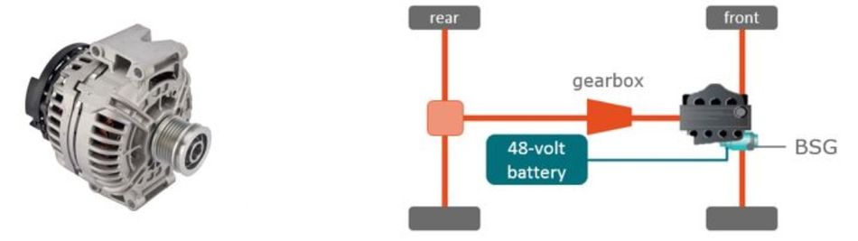
Having a similar appearance as the car alternator (Figure 5a) but slightly bigger in size, the 48-volt starter generator’s initial topology position is at the engine’s belt. The belt-driven starter generator (BSG), also known as P0 architecture (Figure 5b) is a cost-effective solution which can provide up to a 15% reduction in CO2. Looking at some boost recuperation systems (such as Bosch’s), the maximum power ratings are around 10 kW for mechanical output in boost mode and 12 kW for electrical output during recuperation – both at 48-volts. While these numbers are rated for short periods of time, the BSG’s continuous power can reach up to 5 kW with maximum efficiency of 85%.
However with tightening emission regulations, automotive Tier 1 suppliers have developed different starter generator topologies to further reduce the CO2 footprint of 48-volt mild hybrid vehicles. In ascending order, these configurations offer better emission reduction but become increasingly complex and costly.
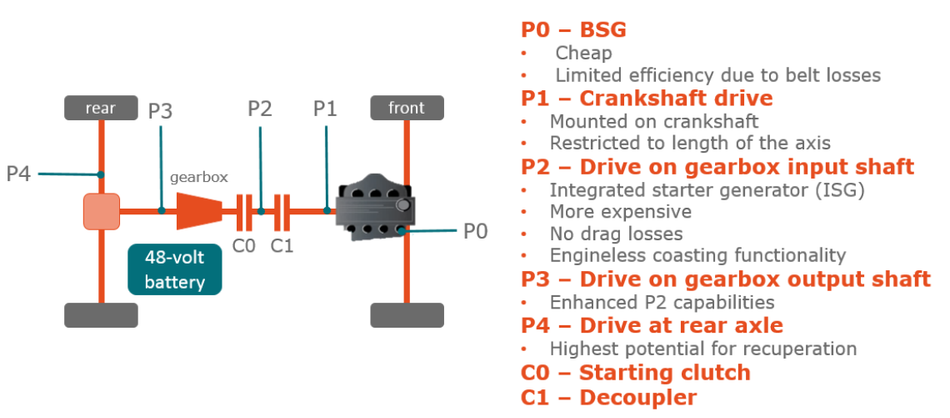
Crankshaft mounted starter generator (P1)
As the name suggests this solution has the starter generator mounted directly on the crankshaft (which converts the linear motion of pistons into rotary motion). This provides higher torque than the P0 architecture due to the absence of a belt drive, and with no belt losses there is greater efficiency. The maximum power required is 10 kW but the efficiency goes up to 94%. However one significant limitation of this solution is that torque requirements can be demanding, due to no torque/speed ratio between the crankshaft and the starter generator. An example of this topology is the 2010 Mercedes-Benz S400 BlueHybrid.
Shaft mounted machine (P2/P3)
Both P0 and P1 architectures are mounted on the engine, but there are other mounting options such as having the 48-volt electrical machine on the gearbox’s input/output shaft (P2/P3 respectively). By providing a mechanical disconnect, this translates to improved energy flow efficiency and allows for the provision of hybrid functions (e.g. e-drive).
The P2 architecture is ether integrated into the transmission on the input shaft or attached on the side, and results in increased energy recuperation and electrical drive capabilities. Mounting the solution on the output shaft (P3), provides the highest level of the above-mentioned benefits. The obvious disadvantage of the shaft mounted electrical machine is the cost of integration.
Rear axle mounted electrical machine (P4)
The ultimate architecture at this time involves mounting at the rear axle drive (P4). This provides the vehicle with 4-wheel drive capabilities, with the combustion engine at the front and the electrical machine at the back. Maximum power requirement of the P2-P4 architectures can reach up to 21 kW with an efficiency of 95%. Moving the starter generator closer to the rear axle also provides more hybrid functionality to the vehicle. The new 48-volt machine is able to reduce the CO2 emissions by up to 21% in urban driving environment depending on its architecture.
What is more, this high-power application requires a significant portion of electronics to drive it. Power MOSFETs play a key role in these electronic modules, but they need to be capable of withstanding worst case scenarios such as excessive currents and thermal leakages.
After talking about the 48-volt architecture and describing some of the main applications, it is imperative we delve into the electronic requirements of these new systems, which I'll do in the next sections.
Power MOSFETs – the muscle in 48V systems
A brief introduction into why the capabilities of power MOSFETs make them ideal for automotive applications like 48-volt starter generators.
The rise of automotive semiconductors
Semiconductors are an essential element in today’s technical applications because of their ability to both conduct and insulate the flow of electricity under certain conditions. In a way they act as the ‘valves’ of the system, controlling the flow of electricity in the electronic circuit. And of course, systems require different types of devices depending on what the desired outcome is – rectification, amplification or switching for example.
Power semiconductors are used in many automotive applications, including the 48-volt starter generator. The main benefit of these devices is their ability to withstand high voltages and large currents without being damaged. In the last decade, power requirements of automotive applications significantly increased which led to the higher demand for efficient power semiconductors.
So what is a power MOSFET?
There are different types of power semiconductors - power diode, thyristor, bipolar-junction transistor (BJT), insulated-gate bipolar transistor (IGBT) and the metal-oxide-semiconductor field-effect transistor (MOSFET). The use of each one of these devices depends on the application’s requirements.
Putting our focus on MOSFET devices, these are voltage-controlled switches with faster switching capability compared to other power semiconductors. This is particularly useful for applications which require fast operational speeds (e.g. motor control). Figure 7 shows the schematic representation of a basic MOSFET device.
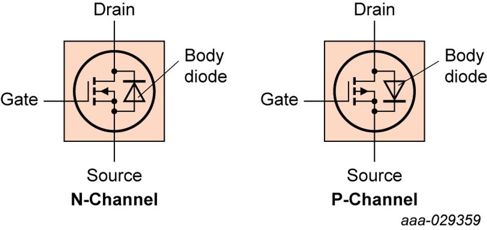
The MOSFET is controlled through a Gate terminal which acts like a bridge between the Drain and Source terminals where the current flows. This bridge can be opened and closed depending on whether a voltage is applied to the terminal. How much current flows between the Drain and Source is proportional to the amount of voltage applied.
Depending on how the transistor is fabricated and which material is used to create the channel affects how the gate works. In N-channel semiconductors, most of the charge carriers are electrons, while in P-channel types the charge carriers are electron holes. In other words, N-channel devices require a positive gate voltage while P-channel need negative gate voltage to operate.
Role of power MOSFETs in 48-volt starter generator
Having scratched the surface of MOSFETs, it is worth discussing how such devices find their place in the 48-volt starter generator. The starter generator consists of a multi-phase motor which needs to be managed by a sophisticated control circuitry. MOSFETs provide the muscle in 48V systems, and prove to be advantageous over older BJT switches because of their lower conduction losses and faster switching speed. Figure 8 displays a typical 3-phase motor control circuit which utilizes 6 MOSFET switches in an H-bridge configuration. The reason for phasing is to provide better efficiency of operation as well as cost.
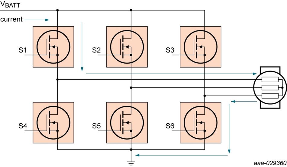
In a motor control circuit, only one switch from the power supply side and one from the ground end can operate at a single time, provided they are not connected in series. For example, closing S1 and S6 gives a smooth connection whereas closing S1 and S4 together will lead to a short circuit. Furthermore, the transition between switch phases needs to be managed carefully to avoid mis-connections. This is achieved by a short dead time (normally nanoseconds) where all switches are open.
Figure 8 also highlights the correct flow of current for one of the phases where the flow goes through S1, then to the motor and finally to ground through S6. The current then transfers to subsequent phases through S2 and S4, and S3 and S5, before going back to the first phase.
Normally, the motor control topology of a 48-volt starter generator can be greater than 3-phase (e.g. 6-phase) to address the needs of higher power and better efficiency. The current flowing to the multiphase motor is typically in the range of 200 A to 520 A. This current is quite significant and imposes the use of MOSFETs with very low RDS(on) and high ID current capabilities.
The switches used in Figure 8 are chosen to be N-channel because of n-type’s lower RDS(on). This leads to less power consumption and lower power losses, where the power losses equal the resistance times the square of the current (Ploss=I2*R). Preferred MOSFET devices must be able to handle ID MAX of 250 A – 300 A per piece and have RDS(on) lower or equal to 1 mΩ.
On the other hand, the MOSFET devices must also be capable of handling the voltage spikes of the 48-volt system. Voltage spikes are short and fast electrical bursts of energy (transients) in the supply voltage. Without such capability, the switch will be easily destroyed. Hence, electronic engineers look at devices able to withstand at least 1.5x times the system voltage. In the case of 48-volt systems, this means MOSFETs with voltage between the drain and source (VDS) [3] of 80 V and sometimes 100 V.
Encapsulated or bare-die
The thermal aspects of MOSFET switches are of great importance in high-power applications. Therefore there is a specific need for reliable MOSFET packaging, capable of meeting exacting thermal requirements and board level reliability. For a 48-volt starter generator, where power levels can reach up to 25 kW, no such packaging solution is available, which forces manufacturers to use bare die (packageless) solutions.
Even though the starter generator is not addressable by a discrete packaged solution, many other 48-volt applications (48/12 V DC/DC converter, electric supercharger, battery management systems, etc.) can benefit from this luxury. In the final section I will discuss these packaged solutions in detail and explain how they fit into applications such as the 48/12 V DC/DC converter.
The right package for 12 / 48 V DC/DC conversion
In this final section I explain the benefits of the latest MOSFET packaging solutions and why they should be the preferred choice for most automotive systems. Furthermore, we delve into one of the essential 48-volt systems – the 48 V DC/DC converter – and take a quick look at its basic function and power semiconductor contents.
Power MOSFET packaging – the benefits of copper clip
Traditionally power MOSFET packages were quite significant in terms of size, as this provided better thermal dissipation and performance, increasing overall safety and reliability of the device. Conventional packages such as TO-220, TO-247, I²PAK, DPAK and D²PAK have been used for years and some suppliers still make use of them due to their cost and known characteristics.
However, as automotive electronic systems have become more advanced, power MOSFET devices have had to become more efficient. This has led to the emergence of packages using copper clip bonding technology rather that the wire bonding technology for the MOSFET terminal connections. Copper clip technology provides numerous benefits including reduced total device resistance, improved power density and better switching performance.
One of those package designs, the LFPAK, has gained significant acceptance for many automotive applications since its introduction back in 2003. A major benefit of LFPAK is its improved performance in thermally demanding environments, where the board reliability of the device is crucial. Another key technology factor is the shorter leads (legs) of the device which contribute significantly to the lower inductance and package resistance. The exposed leads also contribute to better stress handling compared to packages such as power quad flat no-lead (PQFN) packages where micro pins are used instead of leads.
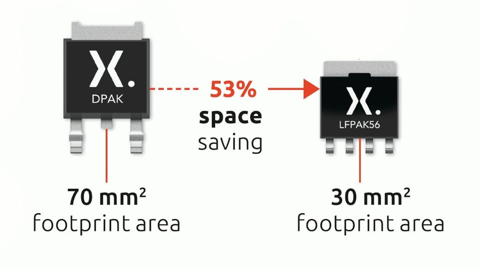
Figure 1 shows the package footprint improvement of LFPAK compared to traditional wire-bonded DPAK. It is estimated that a 5 mm x 6 mm LFPAK (or LFPAK56) has less than half of the total footprint of a DPAK while offering lower package resistance and higher power density. For more information on the benefits of LFPAK and its copper clip technology, take a look at this quick learning video.
48-volt DC/DC converter
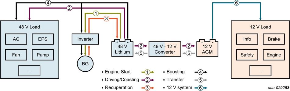
The 12 to 48 V DC/DC converter plays an essential role in 48-volt automotive systems. As its name suggests, it converts the voltage level from the 48-volt bus to the 12-volt one and vice versa. The converter aims to increase the efficiency of the system and provide a stable power supply even when the engine is turned off during start-stop or while the vehicle is coasting.
Figure 3 summarises the converter’s functions between the two voltage levels. In the context of a 48-volt mild hybrid, whenever the belt-starter generator (BSG) recovers energy back to the 48-volt battery, the converter can transfer this power to 12-volt loads. As already mentioned, the converter can also transfer power from the 12-volt battery to start the engine and support the driving functionality during coasting on the motorway.
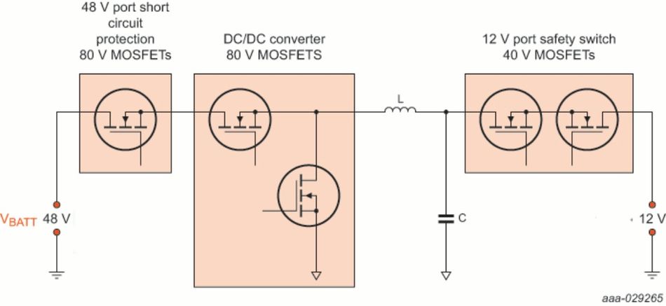
Looking at the 48-volt DC/DC converter from a power semiconductor perspective, the converter requires sophisticated MOSFET circuitry for short circuit protection, phase switching and 12-volt reverse battery protection. Figure 4 highlights these main areas and the corresponding MOSFET voltage requirements. Additionally, the MOSFET switches are required to have very low resistance (RDS(on) < 1 mΩ) to reduce losses and be capable of dissipating a significant amount of generated heat.
What the future holds
In this article I aimed to introduce the growing topic of vehicle electrification and how it could impact the automotive and power semiconductor industries. It was important to delve into some of the 48-volt systems and understand how they operate and what requirements they have. There is no doubt that 48-volt will become the new mainstream system in automotive. It will allow internal combustion engine cars to become more efficient by enabling the vehicle’s kinetic energy to be recovered back to the 48-volt battery.
In the long run, the 48-volt system may also be applied to other forms of electrified vehicles such as full hybrids, plug-in hybrids and even fully electric vehicles. From a power semiconductor, more specifically MOSFET point of view, the demand for better and more efficient MOSFETs will continue. Hence, manufacturers need to stay innovative and make sure they keep with the latest technology trends. That is why packages such as LFPAK will play an important role in improving the system efficiency and safety.