Sparse Infill Density Explained: Slicer Terminology and Best Settings
A guide for engineers about what sparse infill density refers to, with practical recommendations backed by research and slicing software data.

18 Mar, 2026. 9 minutes read
Most 3D printed parts are partly hollow inside—and the interior structure matters more than many beginners realize. Instead of 3D printing a part completely solid, slicers typically fill the interior with a patterned lattice that supports the outer walls. The density of this internal structure strongly influences how strong, heavy, and material-efficient a print will be.
Terminology can vary across 3D printer slicing software. Some slicers use the term “sparse infill” to describe any interior structure that is not fully solid, while others simply refer to it as “infill” without a separate label. In the first case, “sparse infill density” refers to how tightly packed that interior pattern is. Different slicing software may display or organize the setting differently, but all control the same basic variable: how much material fills the inside of a print.
Understanding sparse infill density is important because it directly affects print performance. Lower densities reduce filament use and speed up prints, while higher densities increase strength and stiffness. In the sections that follow, we’ll examine how different infill densities affect print time, material consumption, and mechanical performance, along with practical guidance for choosing the right setting.
What Is Sparse Infill?
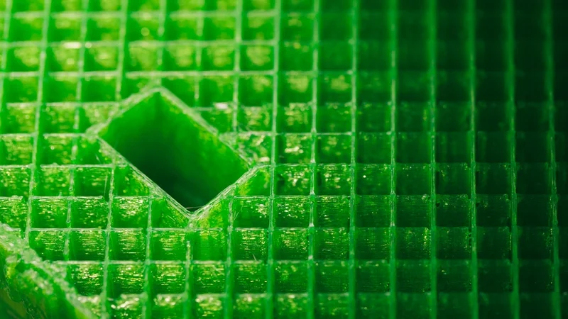
In 3D printing, infill refers to the internal structure that fills the inside of a 3D printed part. Instead of making objects completely solid, most slicers generate a repeating pattern inside the outer walls. This pattern provides structural support while reducing material use and print time. The result is a part that is strong enough for many applications without requiring the filament, time, or weight of a fully solid print.
The term “sparse infill” is where some terminology confusion appears. In several modern slicers, sparse infill refers to the patterned interior used in most prints—the lightweight lattice that sits between the outer walls and top/bottom layers.[1][2] These programs often contrast sparse infill with solid infill, which is used in certain layers or regions where the part needs to be fully dense. On the other hand, many slicers simply refer to the sparse internal regions as infill.
Several popular slicers use the term “sparse infill” directly in their settings and documentation, including:
OrcaSlicer
Bambu Studio
Creality Print
These slicers all trace their lineage back to Slic3r, an open-source slicing engine that helped define many of the modern infill concepts used today. Interestingly, Slic3r itself—along with software like Cura and PrusaSlicer—generally uses the simpler term “infill” rather than “sparse infill.”[3] Over time, forks and derivatives introduced additional terminology to distinguish between patterned interior fill and fully solid regions.
In practical terms, (sparse) infill works by generating geometric patterns—such as grid, gyroid, or triangular structures—inside the model. These patterns distribute loads while leaving open space between lines of plastic. Because the outer walls of a print typically carry much of the mechanical stress, this internal lattice can provide adequate strength without filling the entire volume with material.
It is also worth noting that some people will use the phrase sparse infill informally to mean low-density infill, as Creality has done in some blog posts.[4] In this usage, the term does not distinguish between different types of infill; it simply refers to interior fill that leaves a lot of empty space. While this interpretation is common in discussions and tutorials, slicer software typically uses the term more specifically to contrast patterned interior fill with solid infill regions.
Understanding this terminology helps clarify the settings you see in slicing software. Whether it is labeled infill or sparse infill, the concept remains the same: a structured internal lattice designed to balance strength, weight, material usage, and print time.
Why Sparse Infill Density Matters
Sparse infill density—or just infill density, depending on your software—is one of the most important settings in a slicer because it directly affects how a printed part behaves. (Note that some versions of Creality Print call this parameter “infill sparse density,” which is grammatically and technically confusing.) By adjusting how much internal structure a part contains, you control the balance between strength, weight, material use, and print time. Two prints with identical outer dimensions can perform very differently depending on the infill density used.
At a basic level, sparse infill density determines how tightly packed the internal lattice of a part is. Low densities create large gaps between infill lines, producing lighter parts that print quickly. Higher densities fill more of the interior, creating stronger parts that resist bending and compression.
Sparse infill density affects:
Mechanical strength: Denser infill generally increases resistance to compression and bending.
Print time: Higher densities require more extrusion paths, which increases print duration.
Material consumption: More infill means more filament used per part.
Weight: Low-density infill produces significantly lighter prints.
Top surface quality: Extremely low densities may cause top layers to suffer sagging or pillowing.
Even small changes can have noticeable effects. Increasing infill density from a very low level to a moderate one can significantly improve stiffness without dramatically increasing print time.
Below is a simplified comparison of how different infill densities typically behave:
Infill Density | Typical Characteristics | Common Uses |
Low | Very lightweight, fast to print, minimal internal support | Decorative models, visual prototypes |
Medium | Balanced strength and material use | Functional parts, enclosures |
High | Stronger internal support, heavier and slower to print | Load-bearing parts, mechanical components |
It’s also important to remember that infill density works together with other settings. Wall thickness, top and bottom layers, and infill pattern can sometimes influence strength more than density alone. For example, increasing wall count often improves strength more efficiently than dramatically increasing sparse infill density.
In practice, most prints do not require extremely high densities. Because the outer walls carry much of the structural load in FDM parts, moderate infill levels are often sufficient for everyday prints. The key is selecting a density that provides enough internal support without wasting material or time.
Factors Determining the Ideal Sparse Infill Density
Choosing the right sparse infill density is rarely a universal decision. The best infill settings depend on several interacting factors, including the geometry of the part, the material being printed, and the intended use of the object. By considering these variables together, you can select an infill density that provides sufficient strength without unnecessarily increasing print time or filament consumption.
Infill Pattern
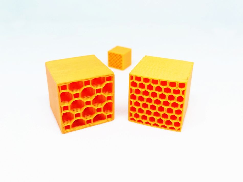
The infill pattern generated by the slicer plays a major role in determining how much density is needed. Different patterns distribute forces in different ways, which means two prints with identical densities may perform differently depending on the pattern used.
For instance, simple grid patterns provide strong support along straight axes, while triangular patterns improve rigidity. Gyroid infill is often praised for its excellent strength-to-weight ratio and more uniform stress distribution. Because some patterns inherently resist deformation better than others, switching patterns can sometimes allow you to lower sparse infill density without sacrificing performance.
Patterns also influence how well top layers are supported. Denser or more evenly distributed patterns can reduce the risk of sagging in upper surfaces.
Recommended reading: Cura Infill Patterns: What They Are and When to Use Them
Material
The filament material used in a print affects how much internal support is required. Plastics differ significantly in stiffness, flexibility, and layer adhesion, all of which influence the appropriate sparse infill density.
Common examples include:
PLA: A relatively stiff material that often performs well with moderate densities.
PETG: Slightly more flexible than PLA, sometimes benefiting from higher densities in functional parts.
ABS: Durable and impact-resistant but may require increased density for load-bearing applications.
Flexible filaments introduce additional considerations. Materials such as TPU or TPE behave very differently from rigid plastics. Because they bend easily, very low densities can produce parts that feel overly soft or unstable, while extremely high densities can make flexible parts too stiff.
For flexible prints, many users combine moderate infill densities with patterns that deform smoothly, such as gyroid or lines. These patterns allow the part to flex more uniformly compared with rigid grid-style structures.
Composite filaments like PETG-CF have different requirements. Carbon fibers improve strength markedly at higher densities (50% or more), while lower densities may not fully utilize the reinforcement.
On the other hand, exceptionally strong engineering plastics like PEEK are inherently strong, so moderate densities (30–50%) often provide sufficient strength even for load-bearing parts while minimizing warping and print time.
Recommended reading: Infill Percentage: Best Infill for TPU 3D Prints and More
Part Application
The purpose of the printed object strongly influences how much internal structure it needs. Decorative objects usually require minimal internal support, while mechanical parts may need much more.
Typical approaches include:
Application Type | Density Strategy |
Decorative models | Low sparse infill density (5–15%) |
Visual prototypes | Low to moderate density (5–25%) |
Functional rigid parts | Moderate density (30–50%) |
Load-bearing components | Higher density (50–90%) |
Flexible parts (e.g., gaskets, grips) | Moderate density (5–30%) |
Flexible components often rely on infill structure to control how the part compresses or bends. Too little infill can make the part collapse easily, while too much can eliminate the desired flexibility.
Part Size and Geometry
The shape and dimensions of the model also affect optimal density. Large flat surfaces may need more internal support to prevent sagging in top layers. Parts with thin features or tall structures can also benefit from higher densities to maintain rigidity.
Conversely, small parts with thick outer walls may remain strong even with relatively low sparse infill densities.
Print Time and Material Efficiency
Finally, practical considerations often influence infill choices. Higher densities increase both print time and filament usage, sometimes dramatically. For prototypes or large models, lowering sparse infill density can significantly reduce production time while still producing acceptable results.
Research on Sparse Infill Density
Research into infill density sometimes reveals a non-linear relationship between how much plastic is inside a part and how strong it becomes. In theory, increasing density should increase strength because more material carries the load. Experiments broadly confirm this trend: for example, a study in the Journal of Engineering Technology and Applied Physics found that raising PLA infill density from 40% to 80% significantly improved tensile strength and stiffness in FDM specimens.[5]
However, some tests show that the relationship is more complicated. A recent materials study reported that mechanical performance does not always increase with density; in a test with PLA, researchers found that “excessive densification can generate internal constraints and premature cracking,” resulting in a test specimen with 30% infill density outperforming ones with 60% and 100% density.[6] Very high densities can also lead to overextrusion issues.
These findings explain a counterintuitive observation sometimes reported by makers: 100% infill is not always the best option, even when strength is the highest priority. Fully solid prints can trap residual stresses, amplify over-extrusion errors, and reduce the structure’s ability to absorb energy. Slightly lower densities—often combined with thicker walls—can therefore produce parts that are lighter, easier to print, and often just as strong in real-world use.
Conclusion
Sparse infill density might look like a small setting in a slicer, but it has a big impact on how a print turns out. By adjusting how much internal structure a part contains, you’re essentially deciding how the printer balances strength, weight, material use, and print time. Two parts with identical outer dimensions can behave very differently depending on how dense their internal lattice is.
The ideal sparse infill density depends on context. Material choice, infill pattern, part geometry, and the intended use of the object all influence how much internal support is necessary. A decorative print might work perfectly well with very low density, while functional or load-bearing parts usually benefit from more internal structure.
Once you understand how these factors interact, infill density becomes less of a guess and more of a tuning tool. With a few adjustments, you can make prints faster, lighter, or stronger—depending on what the part actually needs.
Frequently Asked Questions
What is sparse infill in 3D printing?
Sparse infill refers to the patterned internal structure inside a print that isn’t fully solid. Some slicers, like OrcaSlicer, Bambu Studio, and Creality Print, explicitly label this as sparse infill to differentiate it from solid infill, while others simply use the term infill. Regardless of the label, the concept is the same: a lattice of infill lines that supports top layers and the outer walls while saving material and reducing print time.
How does infill density affect print strength and durability?
Higher infill density improves mechanical properties, load-bearing capacity, and durability, but also raises material consumption and print time. Lower densities make prints lighter and faster but can reduce stiffness and stability, especially for functional parts or prototypes.
Which sparse infill patterns are best for strength versus speed?
Gyroid infill and honeycomb provide balanced strength with efficient material usage, ideal for high-strength parts. Rectilinear infill and zig-zag patterns are faster to print, making them suitable for prototypes or decorative models. Concentric patterns improve top surface quality and layer support under wide overhangs.
How can modifiers and layer-specific settings affect sparse infill?
Many slicers, including Cura, PrusaSlicer, and Bambu Lab, allow modifiers to vary infill density in specific regions of a part. For example, areas that need higher strength can use higher density or gyroid infill, while low-stress areas use low-density patterns to save material and reduce print time. These settings give more control over internal support without affecting the entire part.
Does sparse infill affect print quality or top layers?
Yes. Low-density sparse infill (or sparse sparse infill, if you want to mix definitions) may cause sagging or uneven top surfaces, especially with wide overhangs. Denser patterns or concentric infill under top layers improve finish. Layer height and retractions also influence overall print quality.
How do I choose the right sparse infill density for my part?
Consider material, function, and geometry. For load-bearing or high-strength parts, use higher density. For lightweight prototypes, low density saves material and print time. Flexible parts benefit from moderate density and patterns that deform evenly.
How do adaptive cubic and lightning infill affect print speed?
Both adaptive cubic and lightning infill adjust infill percentage and print paths to reduce unnecessary extruded material. This helps maintain part strength while improving print speed and reducing filament usage.
References
[1] OrcaSlicer Wiki. Strength settings: infill [Internet]. GitHub: OrcaSlicer; 2025 Sep 9 [cited 2026 Mar 11].
[2] Bambu Lab. Strength advanced setting [Internet]. Shenzhen: Bambu Lab; [cited 2026 Mar 11].
[3] Hodgson G, Ranellucci A, Moe J. Print settings. In: Slic3r Manual [Internet]. [cited 2026 Mar 11].
[4] Creality. 3D printing infill patterns: strength, speed, and efficiency [Internet]. Shenzhen: Creality; 2025 Dec 19 [cited 2026 Mar 11].
[5] Muzli MF, Ismail KI, Yap TC. Effects of infill density and printing speed on the tensile behaviour of fused deposition modelling 3D printed PLA specimens. Journal of Engineering Technology and Applied Physics. 2024 Sep 15;6(2):1-8.
[6] Hozdić E, Hozdić E. Mechanical Parameters and Microstructural Evolution of FDM-Printed PLA and PLA+ CF Under Variable Infill Architecture and Lubricant Exposure. Polymers. 2025 Dec 26;18(1):72.