Solid Oxide Fuel Cell: How It Works, Materials, and Design Trade-Offs
A solid oxide fuel cell converts fuel directly into electricity through a ceramic electrolyte that conducts oxygen ions at high temperatures. This guide covers the electrochemistry, the material choices, where the efficiency really comes from, and the degradation mechanisms.

29 Sep, 2026. 17 minutes read
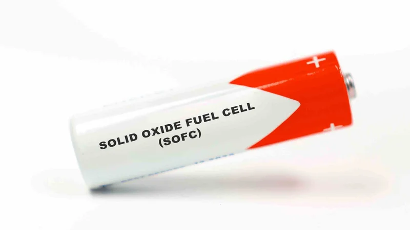
A tubular Solid Oxide Fuel Cell
Key Takeaways
- A solid oxide fuel cell (SOFC) uses a dense ceramic electrolyte, usually yttria-stabilized zirconia, that conducts oxygen ions from the cathode side to the anode side at 500 °C to 1000 °C.[1][2]
- High operating temperature buys you fuel flexibility. Nickel in the anode reforms hydrocarbons internally, and hydrogen and carbon monoxide oxidize as fuel, so you don't need platinum or an external reformer.[3][4]
- Commercial systems specify 53% to 65% electrical efficiency (LHV) on natural gas, and one reaches above 90% total efficiency once the exhaust heat is captured.[5][6]
- The same temperature that buys fuel flexibility also limits the technology: thermal cycling cracks brittle ceramics, chromium evaporates from steel interconnects onto the cathode, and a commercial unit takes about 24 hours to start up.[3][7][5]
- Every material choice is dominated by one number: the thermal expansion coefficient. Nickel sits at 13.3 × 10⁻⁶ K⁻¹, YSZ at 10.5 × 10⁻⁶ K⁻¹, and matching them across the stack is the central mechanical design problem.[8]
What Is a Solid Oxide Fuel Cell?
A solid oxide fuel cell is an electrochemical device that converts the chemical energy of a fuel and an oxidant directly and reversibly into electrical energy. It is fundamentally different from a heat engine, so the efficiency limit that governs thermal cycles does not set its ceiling.[9]
The defining component of a solid oxide fuel cell is a solid ceramic electrolyte. It’s placed between an anode and a cathode, and conducts the oxygen ions formed by the electrochemical reduction of molecular oxygen from the cathode side to the anode side, while blocking electrons and gas.[2]
Because the electrolyte is a ceramic rather than a polymer or a liquid, it only conducts usefully when hot. The U.S. Department of Energy classifies SOFCs as operating from 500 °C to 1000 °C, with stack sizes from 1 kW to 2 MW and about 60% electrical efficiency.[1]
That single design choice, a ceramic electrolyte and the temperature it demands, explains almost everything else about the technology, such as the fuel flexibility, the efficiency, the applications, and the failure modes.
Recommended Reading: What Is a Fuel Cell? Theory, Components, Types, and Applications
How a Solid Oxide Fuel Cell Works
The cell splits one oxidation reaction into two half-reactions separated by the electrolyte, and forces the electrons to take a detour through your load.
Charge-Carrying Oxygen Ions
At the cathode, oxygen from the air is reduced. Oxygen atoms are reduced on the porous cathode surface by electrons arriving from the external circuit, forming oxygen ions.[3]
Cathode: ½O₂ + 2e⁻ → O²⁻
Those oxide ions then diffuse through the dense electrolyte toward the fuel-rich, porous anode. Fuel diffuses through the anode to the anode/electrolyte interface, where it reacts catalytically with the oxygen ions and releases electrons.[2]
Anode: H₂ + O²⁻ → H₂O + 2e⁻
Overall: H₂ + ½O₂ → H₂O
This is the key structural difference from a proton exchange membrane cell. In a PEM fuel cell, the electrolyte is a perfluorosulfonic acid polymer that carries protons.[1] Moreover, in a PEM cell, protons cross toward the oxygen.
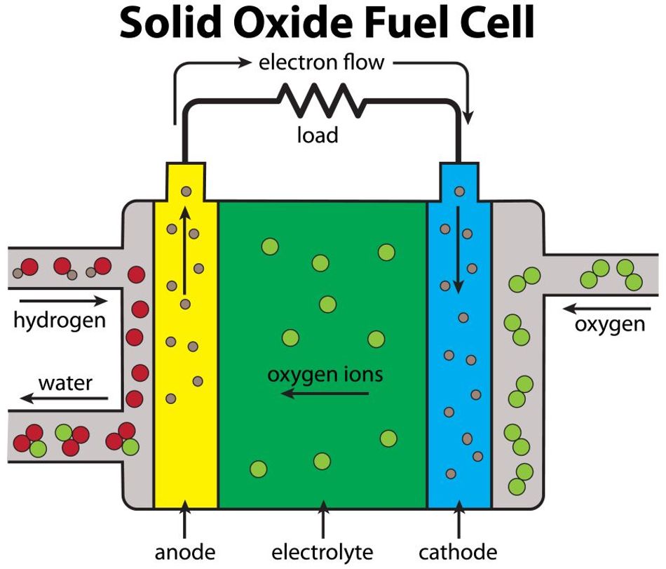
In SOFC, the oxygen ions cross toward the fuel, so the product water forms on the anode side rather than the cathode side. Also, it allows the fuel stream to contain species other than hydrogen.
Carbon monoxide oxidizes under the same conditions and produces carbon dioxide as a result. Both hydrogen and carbon monoxide serve as fuels in a SOFC.[3] A commercial system running on liquefied natural gas therefore runs two electrochemical reactions in parallel inside the stack:[5]
H₂ + ½O₂ → H₂O
CO + ½O₂ → CO₂
The Need for Stack and Interconnects
A single cell produces about 1 V at no load. A recent cell study concludes that the voltage drops from 0.98 V to 0.73 V across the measured current range at 800 °C, and from 0.75 V to 0.53 V at 500 °C.[10]
Therefore, practical use of SOFC only comes with stacking, where individual cells are linked with a metallic interconnect in electrical series to increase voltage and power.[2]
Power increases with active area and current density. Also, cell-level power density is strongly temperature-dependent. The study of nickel-assisted gadolinium-doped ceria anodes measured approximately 0.094, 0.118, 0.146, and 0.184 W/cm² at 500 °C, 600 °C, 700 °C, and 800 °C, respectively.[10] As the temperature is raised from 500 °C to 800 °C, it roughly doubles the power density. So it clearly indicates why SOFC must be kept hot.
The electrochemical reaction also produces a large amount of heat, which an integrated heat management system can put to use rather than reject.[3] In a full plant, that heat preheats incoming fuel and air, drives the internal reforming step, and in hybrid systems drives a gas turbine.[4]
Cell Materials Layer by Layer
Both electrodes and the electrolyte are made of ceramic materials, because the high operating temperature prevents the use of cheaper metals.[3] Each layer has a different job and a different failure mode.
Layer | Typical material | Function | Key constraint |
Electrolyte | 8 mol% Y₂O₃ stabilized zirconia (8YSZ) | Conducts oxygen ions, blocks electrons and gas | Dense and leak tight, thin enough to keep ohmic loss low |
Anode | Ni-YSZ cermet | Oxidizes fuel, reforms hydrocarbons, conducts electrons | Ni coarsening, coking, sulfur poisoning |
Cathode | LSM-YSZ composite or LSCF | Reduces oxygen to oxygen ions | Chromium poisoning, thermal expansion mismatch |
Interconnect | Ferritic stainless steel or doped lanthanum chromite | Connects cells in series, separates fuel and air | Chromium evaporation, oxide scale resistance |
Seals | Glass-ceramic | Gas-tight closure at cell edges and manifolds | Must survive thermal cycling without cracking |
Ceramic Electrolyte
The SOFC electrolyte must meet several key requirements. These properties include [11]:
Dense and leak-tight formation
Stability in oxidizing and reducing conditions
Good ionic conduction at operating temperatures
Non-electron conductivity
Thin structural formation to oppose ionic resistance
Good thermal shock resistance
Economic viability for large-scale production
While some of these requirements are somewhat contradictory, they are critical for effective cell performance. It’s important to note that ionic conduction in ceramics is a thermally activated hopping process, depending heavily on temperature. At high temperatures, the conductivity can reach 1 S/cm, the same order of magnitude as a liquid electrolyte. For a practical cell, a desirable conductivity is 0.01 to 0.1 S/cm for an electrolyte 1 to 100 µm thick.[8]
Limitations with Zirconia and Its Remedy
Pure zirconia cannot do this job for two reasons:
It is monoclinic at room temperature and changes to the denser tetragonal phase from around 1000 °C.
The phase change involves a large volume change that causes extensive cracking.[11]
Doping is a good fix for both problems. Zr⁴⁺ is too small to sustain the fluorite structure at low temperatures, so it is partly substituted with a larger, lower-valence cation, and charge neutrality then requires oxygen vacancies, which are exactly what allows oxygen ion migration.[11]
Adding 8 mol% Y₂O₃ (8YSZ) is enough to form fully stabilized zirconia, giving a cubic solid solution with no phase transformation from room temperature up to 2500 °C.[11]
Current cells use either 3YSZ or 8YSZ. YSZ is not the best ion conductor available, but it is the cheapest to process and has low enough electronic conductivity, and its abundance, chemical stability, and non-toxicity make it the most suitable material at present. Its drawbacks are a high thermal expansion coefficient and the sealing problems that follow.[11]
The Anode and the Triple Phase Boundary
Nickel is used as the anode material because it is economical and performs well. However, pure nickel flakes off the electrolyte due to poor adherence and mismatched thermal expansion. Mixing it with zirconia to form a cermet solves this issue.[7]
The thermal expansion numbers show why this is not optional. Nickel has a thermal expansion coefficient of 13.3 × 10⁻⁶ K⁻¹, against 12.0 × 10⁻⁶ K⁻¹ for GDC and 10.5 × 10⁻⁶ K⁻¹ for YSZ.[8] Nickel therefore expands roughly a quarter more than the YSZ it is bonded to, which is the mismatch behind the flaking, and mixing zirconia into the anode is what pulls the composite back toward the electrolyte.
Also, the reaction itself needs three phases meeting in the same place. Because gas atoms discharge or absorb electrons at the electrode, a three-phase boundary zone is required, combining a gas phase (which needs high porosity for access), an electrolyte phase for ion transport, and a metal phase for electron conduction.
Nickel-GDC anodes are an alternative to conventional Ni-YSZ, offering improved catalytic behavior and reduced carbon deposition.[10] Anode conductivity is not the bottleneck in either case: a 70 vol% Ni-SDC anode has been measured at roughly 4000 S/cm at 800 °C.[8]
The Cathode
The cathode operates in a highly oxidizing environment, so cheap base metals are impossible, and the best compromise is semiconducting oxides, specifically doped lanthanum cobaltites and manganites.[7]
Lanthanum strontium manganite, La₀.₈Sr₀.₂MnO₃ (LSM), has good electronic conductivity and a matching thermal expansion coefficient. Once operating temperatures dropped below 1000 °C, it became possible to mix LSM with YSZ in a 50/50 proportion to form the first surface on the electrolyte, which extends the reaction zone into the electrode.[7]
The other common choice is lanthanum strontium cobalt ferrite, La₀.₆Sr₀.₄Co₀.₂Fe₀.₈O₃ (LSCF). It has lower power losses at lower temperatures and is less susceptible to chromium poisoning, and it is used with ceria-based electrolytes.[7]
Interconnects, and the Chromium Problem
The interconnect needs to be inert and impervious, and to survive both oxidizing and reducing atmospheres at once, because it has fuel on one face and air on the other.[12]
Doped lanthanum chromite has the necessary properties in systems operating at 1000 °C and can be doped to match the thermal expansion coefficient of LSM, providing cell lifetimes up to 70,000 hours.
Metallic Alloys for Low Temperatures
For lower operating temperatures, metallic alloys can be used instead.[12] Crofer 22 APU is the reference material. It’s a ferritic high-temperature stainless steel designed specifically for SOFCs, containing 20.0% to 24.0% chromium with additions of manganese, titanium, and lanthanum.[13]
Chrome-Manganese Oxide
At temperatures up to 900 °C, a chrome-manganese oxide layer forms on its surface, which has good thermodynamic stability and good electrical conductivity, so the scale conducts instead of insulating.[13]
Evaporation with Stainless Steel
Steel has its own failure mode. If stainless steel interconnects are used, chromium evaporates from the steel and condenses preferentially on the cathode, degrading it. The rate of chromium poisoning decreases with decreasing operating temperature.[7]
The vaporization proceeds through gaseous chromium oxide species formed from the Cr₂O₃ scale.[14] Alloy makers respond by engineering for a low rate of chromium evaporation, which is one of the properties Crofer 22 APU is specified on.[13]
Optimal Operating Temperature
Operating temperature is the master variable in SOFC design, and the industry has spent decades pushing it down. Cell generations are distinguished by exactly this: the operating temperature is between 600 °C and 1000 °C depending on the generation of the fuel cell- first, second, and third- with decreasing operating temperature.[3]
The physics behind the push is simple. A thick electrolyte needs a high operating temperature to reduce its ohmic impedance, because that impedance is proportional to thickness.[14] That is why cell architecture and operating temperature are the same decision [15]:
Cell architecture | What carries the mechanical load | Typical operating temperature | Trade-off |
Electrolyte-supported (ESC) | Thick ceramic electrolyte | 750 °C to 900 °C | Robust and simple, but high ohmic loss forces high temperature |
Fuel-electrode-supported (FESC) | Thick Ni cermet anode | ≤ 750 °C | Thin electrolyte, high performance, but redox and thermal cycling sensitive |
Metal-supported (MSC) | Porous ferritic steel substrate | ≤ 650 °C | Best thermal and redox cycling tolerance, but interdiffusion and oxidation of the metal |
Metal-supported cells show much better stability under rapid thermal and redox cycling than anode-supported cells, because metals have excellent ductility and high thermal conductivity.[14]
With higher temperature, you get better kinetics, easier internal reforming, and higher-grade waste heat, but faster chromium poisoning, more sintering, and no cheap metals anywhere in the stack.
At cooler temperatures, you get metal parts, faster start-up and better cycling, but lower power density and a harder cathode problem.
SOFC Efficiency
Fuel cell efficiency claims deserve scrutiny, so it is worth separating the thermodynamic ceiling from what a shipping product does.
The reversible efficiency of a fuel cell is the ratio of the Gibbs energy to the reaction enthalpy,
η = ΔG/ΔH,
which follows directly from the first and second laws.[9] The practically important consequence is that this ratio falls as temperature rises for hydrogen: the molar Gibbs energy of the reaction drops from about 1.23 V at room temperature to about 0.95 V at 900 °C. In comparison, the reaction enthalpy stays almost constant at about 1.3 V.[15]
Here is what that produces in real, commercially specified systems [6][16]:
System | Rated output | Electrical efficiency | Total efficiency | Fuel |
Bloom Energy Server 6.5 | 325 kW net AC | 65% to 53% (LHV net AC) | Above 90% with heat capture | Natural gas, biogas, blended hydrogen or hydrogen |
Mitsubishi Power MEGAMIE (SOFC plus micro gas turbine) | 210 kW | 53% LHV | 73% LHV (hot water) or 65% LHV (steam) | LNG |
DOE program target | n/a | Above 60% without carbon capture | n/a | Natural gas or coal-derived syngas |
There are two things to consider:
Electrical efficiency is quoted as a range, not a point: the Bloom system is specified at 65% to 53% (LHV net AC) cumulative electrical efficiency.[6] The datasheet does not explain the spread, but a declining band across a service life is what stack degradation looks like, so treat a single-number efficiency claim for any SOFC as a beginning-of-life figure until the vendor says otherwise.
The exhaust heat dictates the total efficiency. The Bloom unit offers over 36% cumulative thermal efficiency with exhaust heat available above 350 °C, giving over 90% total efficiency.[6] The MEGAMIE recovers 86 kW of thermal output as hot water on top of its 210 kW electrical output.[5]
Fuel Flexibility and Internal Reforming
Fuel flexibility is the practical headline advantage of the technology, and it is a direct consequence of temperature.[1] Common hydrocarbon fuels can be used in a SOFC, including diesel, natural gas, gasoline, and alcohols.[3] Commercial systems are specified for natural gas, biogas, blended hydrogen, and hydrogen.[6]
Steam reforming happens inside the cell
Because of the high operating temperature, internal reforming can take place at the anode when steam is added to the fuel.[4] Nickel is not only the electrochemical catalyst, it is also an active reforming catalyst.[7] A methane feed therefore runs through two chemical steps before the electrochemistry:
Methane reforming: CH₄ + H₂O → CO + 3H₂
Water gas shift: CO + H₂O → CO₂ + H₂
Overall: CH₄ + H₂O → CO₂ + 4H₂
Both hydrogen and carbon monoxide can react with the oxygen ions directly, and the shift reaction proceeds at the anode as well because the reaction of CO is slow, producing more hydrogen.[4] In a full plant, the preheater raises fuel and air to near operating temperature and reforms the gas by steam reforming at the same time.[4]
Steam reforming is endothermic, and the stack reaction is exothermic, so running the reforming step inside the anode absorbs heat exactly where it is being produced.
Carbon Deposition Constraint
The price of hydrocarbon fuels is coking. Nickel is susceptible to becoming coated with a carbon layer when reacting with carbon-based fuels, which can prevent further reaction.[7] Two reactions do it:[4]
Boudouard: 2CO → CO₂ + C
Methane cracking: CH₄ → 2H₂ + C
Adding steam to the fuel is the standard countermeasure, since the reforming and shift reactions above consume carbon into gaseous products.[4] Materials help too. Additives to the Ni-YSZ cermet, such as 5% ceria or 1% molybdena, inhibit carbon layer formation,[7] and Ni-GDC anodes show reduced carbon deposition compared with Ni-YSZ.[10]
Sulfur poisons at both electrodes
Only desulfurized natural gas can be used as fuel, because even at high temperature sulfur is absorbed by the anode.[4] The durability of a SOFC is determined mainly by what happens during thermal cycles, redox cycles, and sulfur contamination.[4]
Less widely appreciated is that sulfur attacks the air side too. Airborne SO₂ contaminates cathodes, and LSCF is considered vulnerable because surface-segregated SrO reacts with SO₂ to form SrSO₄. LSM is also contaminated, although the effect may not be as severe as on LSCF.[17]
The recovery behavior differs usefully: the performance of sulfur-contaminated LSM is almost restored on subsequent exposure to clean air, whereas sulfur-poisoned LSCF only partially recovers.[17]
Degradation and Durability
The DOE target frames what "good" means here: less than 0.2% performance degradation per 1,000 hours over an operating lifetime of 40,000 hours, alongside a stack cost target of $225/kW and a system cost target of $900/kW.[16]
That degradation target is demanding but demonstrated. A 1 kW metal-supported stack has run at 0.2% per 1,000 hours over 17,600 hours at 610 °C on reforming gas.[14]
The mechanisms that eat into it are well characterized:
Nickel coarsening. Nickel particles grow and agglomerate at operating temperature, shrinking the triple phase boundary. The scale of the change is large even at first reduction: particle size increased from 3 µm to 10 µm when NiO was reduced to nickel.[14] Ni coarsening and migration over time lead to a decline in electrochemical performance.[10]
Chromium poisoning of the cathode. Chromium evaporates from steel interconnects and condenses on the cathode.[7] It proceeds via gaseous species formed from the Cr₂O₃ scale.[14]
Sulfur contamination. At the anode from fuel, and at the cathode from air.[4][17]
Coking. The activity of the nickel anode decreases due to sintering and coke formation when carbon-containing fuels are used.[4]
Thermal and redox cycling. Thermal cycling can crack the brittle ceramic components,[3] and thermal expansion mismatch and cracking are among the known problems of the flat plate design.[3]
Interdiffusion. In metal-supported cells, elements migrate between the metal substrate and the electrode.[14]
SOFC Compared With Other Types of Fuel Cells
Choosing among the types of fuel cells is mostly a question of operating temperature, which then sets fuel flexibility, start-up behavior, and materials cost.[1]
Type | Electrolyte | Operating temperature | Typical stack size | Electrical efficiency |
Solid oxide (SOFC) | Yttria-stabilized zirconia | 500 °C to 1,000 °C | 1 kW to 2 MW | 60% |
Proton exchange membrane (PEMFC) | Perfluorosulfonic acid polymer | Under 120 °C | Under 1 kW to 100 kW | 60% on direct hydrogen |
Alkaline (AFC) | Aqueous KOH or alkaline polymer | Under 100 °C | 1 kW to 100 kW | 60% |
Phosphoric acid (PAFC) | Phosphoric acid in a porous matrix | 150 °C to 200 °C | 5 kW to 400 kW | 40% |
Molten carbonate (MCFC) | Molten Li, Na, K carbonates | 600 °C to 700 °C | 300 kW to 3 MW | 50% |
The comparison that matters most is against proton exchange membrane fuel cells, since those two dominate the conversation about hydrogen fuel cells. DOE puts both at about 60% electrical efficiency, but on completely different terms.
The PEM figure applies to direct hydrogen and falls to 40% on reformed fuel, whereas the SOFC figure is quoted for a technology whose stated fuels include natural gas and coal-derived syngas.[1][16] The reforming penalty a PEM system pays upstream, a SOFC absorbs inside the anode.
The other structural difference is the catalyst. SOFCs get fast electrocatalytic activity while using non-precious metals,[8] which is why the cost conversation for solid oxide is about steel, ceramics, and manufacturing rather than about platinum loading.
Recommended Reading: PEM Fuel Cell: How It Works, Materials, and Design Trade-Off
Solid Oxide Electrolysis
The same cell runs backward. A solid oxide electrolysis cell (SOEC) is essentially the reverse of a SOFC: instead of using hydrogen to produce electricity, it uses electricity to produce hydrogen.[2] A SOEC can be operated in reverse mode as a solid oxide fuel cell to directly reconvert stored hydrogen to electricity.[15]
High temperature is an even bigger advantage in this direction. Operating a SOEC at the thermoneutral voltage of 1.29 V means no external heating or cooling is needed.[15] High-temperature electrolyzer systems achieve electrical efficiencies of up to 84% (LHV), against 50% to 70% (LHV) for low-temperature electrolyzer systems.[15]
Suggested Reading: Expediting Infrastructure Development for Fuel Cells and Electrolysis to Enhance Hydrogen Energy Use.
Where Solid Oxide Fuel Cells Are Used
Because it takes a long time to reach operating temperature, the best applications for SOFCs are ones that use both the heat and the electricity: stationary power plants and auxiliary power supplies.[3]
Stationary Power Generation and Data Centers
This is the mainstream commercial application. Bloom Energy reports over 1.5 GW deployed across more than 1,200 sites, with installations across retail, data centers, hospitals, sporting arenas, manufacturing, and warehousing.[6] Continuous, high-load, heat-usable sites are exactly the duty cycle the technology wants.
Microgrids and Primary Power
Commercial systems are designed for on-site distributed generation operating 24 hours a day, supporting demand in grid-parallel or in a microgrid architecture.[6] Used this way, a SOFC is primary power rather than a backup generator, which is a different specification problem: you size for baseload, not for outage duration.
Utility-Scale and Distributed Generation
DOE identifies auxiliary power, utility-scale electric systems, and distributed generation installations as SOFC applications.[1]
Biogas and Waste Gas Valorization
Commercial systems list biogas among their fuels alongside natural gas, blended hydrogen and hydrogen, so a site already producing gas can feed the stack with it. Bloom notes that biogas, blended hydrogen, and hydrogen operation need to be arranged with the vendor rather than simply selected.[6]
The scaling behavior is what makes the modular design approach work. Bloom describes a modular architecture of simple repeating elements, so capacity is added by adding units rather than by redesigning around a bigger machine,[6] and DOE frames the technology as applicable at both smaller, modular scale and large scale.[16]
Further Reading: New fuel cell could enable electric aviation
How SOFC Fares in the Environmental Case
The low emissions claim is worth putting numbers on rather than asserting. Because a SOFC is a combustion-less power source, DOE calls it virtually pollution-free, clean energy and notes that it runs almost silently and has few moving parts.[16]
The Bloom datasheet quantifies it: 0.001 kg/MWh NOx, negligible SOx, and 308 to 378 kg/MWh CO₂ at stated efficiency, at under 65 dBA measured at 3 m.[6] The MEGAMIE specifies 15 ppm or less NOx (at 16% O₂ at rated power output) and less than 0.1 ppm SOx.[5]
Suggested Reading: Podcast: Eliminating Emissions With IoT, Shapeshifting Fabrics, Fuel Cell Flight
Design Considerations and Common Mistakes
Sizing for a duty cycle with frequent shutdowns. Cold start on a commercial unit is about 24 hours, against roughly 2 hours for a hot restart.[5] DOE explicitly lists a limited number of shutdowns as a challenge.[1] If your load profile involves daily stops, this is the wrong technology.
Quoting total efficiency when there is no heat sink. Over 90% total efficiency is real, but it requires a use for exhaust heat above 350 °C.[6] Without that, use the electrical number.
Ignoring the thermal expansion budget. Nickel at 13.3 × 10⁻⁶ K⁻¹, YSZ at 10.5 × 10⁻⁶ K⁻¹, and Crofer 22 APU at 11.9 × 10⁻⁶ K⁻¹ at 800 °C all have to live in the same clamped assembly.[8][13] Mismatch shows up as delamination and cracked seals, not as a gradual performance decline.
Treating fuel flexibility as fuel indifference. The cell tolerates hydrocarbons but not sulfur, and it needs enough steam to suppress carbon deposition.[4] Specify a desulfurized supply and a steam addition strategy.
Filtering only the fuel. Cathode air carries SO₂ that degrades LSCF in particular, and the recovery is only partial.[17]
Assuming beginning-of-life performance. Datasheet efficiency is specified as a declining band, not a point.[6] Design the system around end-of-life output, and use the DOE target of under 0.2% degradation per 1,000 hours as your reference for what a good stack should hold.[16]
Vibration. Ceramic parts break easily under vibrational forces, which is a major reason SOFCs suit stationary rather than mobile applications.[4]
Suggested Reading: A disruptive approach to fuel cell tech
Conclusion
A solid oxide fuel cell is best understood as a set of consequences flowing from one decision: use a ceramic oxygen ion conductor as the electrolyte. That choice forces an operating temperature of 500 °C to 1000 °C, and the temperature is what delivers the technology's real advantages: non-precious metal catalysts, internal reforming of hydrocarbon fuels, direct oxidation of carbon monoxide, and exhaust heat valuable enough to push total efficiency above 90%.
The same temperature is the source of every hard problem: brittle ceramics that crack on thermal cycling, chromium that evaporates onto the cathode, nickel that coarsens, sulfur that poisons both electrodes, and a start-up measured in hours rather than seconds.
The engineering work now is mostly about lowering the operating temperature without giving up performance, through thinner electrolytes, alternative ceramics like GDC and LSGM, metal-supported architectures, and cathodes that work below 700 °C. Every one of those moves buys cheaper materials and better cycling and cost-effective power density.
Frequently Asked Questions
1. What is the operating temperature of a solid oxide fuel cell?
DOE classifies SOFCs as operating from 500 °C to 1,000 °C. In practice, the range depends on cell generation and architecture: 600 °C to 1000 °C across generations, with metal-supported cells running at or below 650 °C and electrolyte-supported cells at 750 °C to 900 °C.
2. What fuels can a solid oxide fuel cell use?
Both hydrogen and carbon monoxide serve as fuels, and common hydrocarbon fuels including diesel, natural gas, gasoline, and alcohols can be used. Commercial systems are specified for natural gas, biogas, blended hydrogen, and hydrogen.
3. What is the difference between a SOFC and a PEM fuel cell?
The electrolyte and everything downstream of it. A SOFC uses a ceramic that conducts oxygen ions at 500 °C to 1,000 °C; proton exchange membrane fuel cells use a perfluorosulfonic acid polymer that conducts protons below 120 °C. SOFCs run on non-precious metal catalysts[8] and reform hydrocarbons internally, whereas the 60% PEM efficiency figure applies only to direct hydrogen and drops to 40% on reformed fuel. The trade-off is start-up: DOE lists long start-up time as a SOFC challenge.
4. Why do SOFCs use yttria-stabilized zirconia?
Pure zirconia undergoes a phase change near 1000 °C that causes cracking. Adding 8 mol% Y₂O₃ fully stabilizes the cubic structure with no phase transformation up to 2500 °C, and the doping creates the oxygen vacancies that carry the ionic current. YSZ is not the best ion conductor available, but it is cheap to process, chemically stable, abundant, and non-toxic.
5. How long does a solid oxide fuel cell last?
The DOE target is less than 0.2% degradation per 1,000 hours over a 40,000-hour lifetime. That rate has been demonstrated: a 1 kW metal-supported stack held 0.2% per 1,000 hours over 17,600 hours at 610 °C.
6. Can a solid oxide fuel cell run in reverse?
Yes. A solid oxide electrolysis cell is essentially a SOFC in reverse, using electricity to produce hydrogen rather than hydrogen to produce electricity. SOEC systems reach up to 84% electrical efficiency (LHV), and at the thermoneutral voltage of 1.29 V they need no external heating or cooling.
7. Why does a SOFC take so long to start?
The ceramic components must reach operating temperature, and they have to get there slowly, because thermal cycling cracks brittle ceramics. A commercial unit specifies about 24 hours from cold and about 2 hours from hot. DOE lists long start-up time as a standing challenge for the technology.
References
Comparison of Fuel Cell Technologies, U.S. Department of Energy.
SOFC Operating Principle, U.S. DOE National Energy Technology Laboratory.
Solid oxide fuel cells (SOFCs), DoITPoMS, University of Cambridge.
Solid oxide fuel cells: System and outlook, DoITPoMS, University of Cambridge.
MEGAMIE Solid Oxide Fuel Cell specifications, Mitsubishi Heavy Industries, Energy Systems.
The Bloom Energy Server 6.5 Data Sheet, Bloom Energy, February 2026.
Solid oxide fuel cells: Electrode materials, DoITPoMS, University of Cambridge.
Review of solid oxide fuel cell materials: cathode, anode, and electrolyte, Saddam Hussain and Li Yangping, Energy Transitions, 2020.
Solid oxide fuel cells: Thermodynamics, DoITPoMS, University of Cambridge.
Enhanced power density in solid oxide fuel cells using nickel-assisted gadolinium-doped ceria anodes, PMC.
Solid oxide fuel cells: Electrolyte, DoITPoMS, University of Cambridge.
Solid oxide fuel cells: Interconnection, DoITPoMS, University of Cambridge.
VDM Crofer 22 APU Material Data Sheet No. 4146, VDM Metals, Revision 01, March 2022.
Degradation Mechanisms of Metal-Supported Solid Oxide Cells and Countermeasures: A Review, PMC.
High Temperature Solid Oxide Electrolysis: Technology and Modeling, Mueller et al., Chemie Ingenieur Technik, 2024.
Solid Oxide Fuel Cells, U.S. Department of Energy, Office of Fossil Energy and Carbon Management.
Sulfur Poisoning and Performance Recovery of SOFC Air Electrodes, Frontiers in Energy Research, 2021.
in this article
1. What Is a Solid Oxide Fuel Cell?2. How a Solid Oxide Fuel Cell Works3. Cell Materials Layer by Layer4. Optimal Operating Temperature5. SOFC Efficiency6. Fuel Flexibility and Internal Reforming7. Degradation and Durability8. SOFC Compared With Other Types of Fuel Cells9. Solid Oxide Electrolysis10. Where Solid Oxide Fuel Cells Are Used11. Design Considerations and Common Mistakes12. Conclusion13. Frequently Asked Questions14. References