Modeling Sensing Technologies for Harsh Environments
Article #5 of Connectivity and Sensing in Harsh Environments Series: Protecting sensors without affecting their performance is a challenge when designing sensors for harsh and corrosive environments.

04 Apr, 2022. 8 minutes read

This is the fifth article in a 6-part series featuring topics on Connectivity and Sensing in Harsh Environments. The series will showcase how highly engineered connectivity and sensing solutions enable advancements in manufacturing, transportation, construction, healthcare, energy generation, and consumer products. This series is sponsored by Mouser Electronics. Through the sponsorship, Mouser Electronics shares its passion for technologies that enable smarter and connected applications.
Sensors are everywhere. These devices are crucial components of feedback control systems and help gather data that drives decisions. As gadgets and electronic appliances become smarter and more connected, the number of sensors used in household and industrial applications is bound to go up.
Some sensor applications require the devices to work in harsh and unfavorable environments. In this article, we try to understand how sensing technologies are prepared for enduring harsh environments by analyzing the principles, design considerations, and testing procedures followed during the fabrication and manufacturing of a microelectromechanical system (MEMS) pressure sensor.
Features of modern consumer and industrial sensors
Before taking a look at the design and operation of sensors for harsh environments, it is important to understand the desired features of a reliable and robust industrial sensor. Some of them are:
Compact design
Low power consumption
High accuracy and precision of measurements
Digital interface
Harsh media resistance
Sensor fusion
Optimizing pressure sensors for harsh environments
Pressure sensors are present in various markets such as automotive, industrial, medical, and consumer products. As mentioned before, some of these are present in applications and environments that are not so friendly. In such a scenario, sensors may be subjected to extremes in temperatures, physical strain, dust & liquid ingress, and more.
Many of these applications require specialized sensors designed to withstand exposure to corrosive and hostile chemicals. Often these chemicals exist in the medium in which the sensors are deployed. Ordinary sensors, with no special considerations for harsh environments, would just not work in such situations. The chemicals, in most cases, are in direct contact with the sensor itself, and if the sensor is unable to withstand the environment, it could have adverse effects on the overall functioning of the device and the control system as a whole.
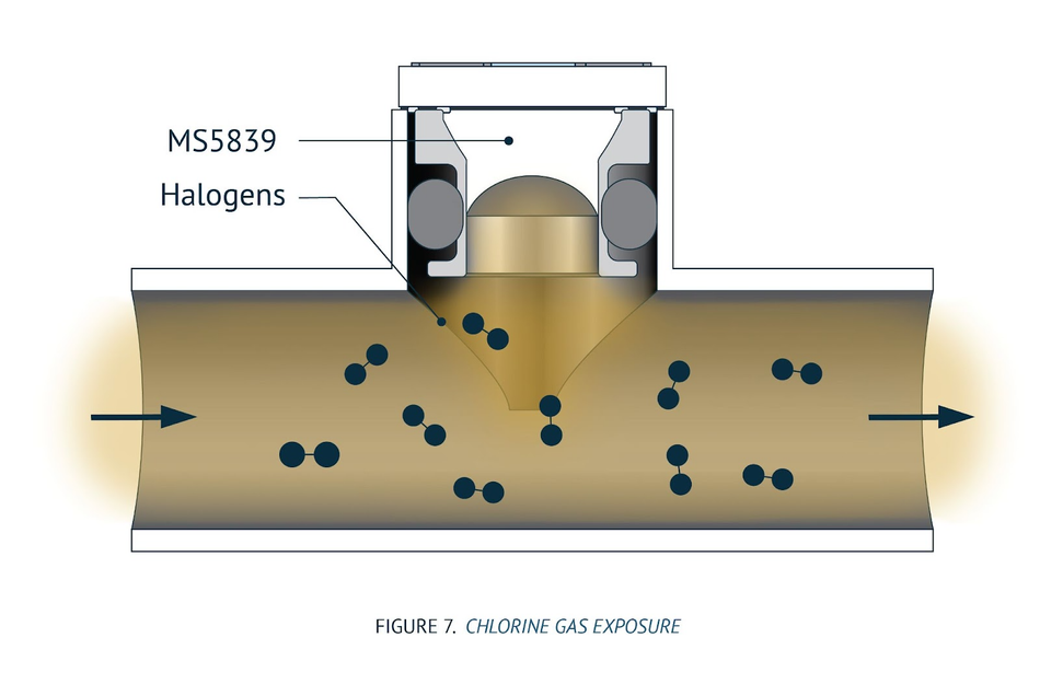
Modern sensors must be designed to withstand and resist attacks by these chemicals to provide reliability and long service life. A basic example of using a pressure sensor in harsh environments could be seen in water-resistant smartwatches. These watches are regularly exposed to water containing chlorine as either a dissolved gas (swimming pool) or in ionic form (ocean water). Chlorine is a strong oxidizer that quickly corrodes most metals and can do irreversible damage to the product. Pressure sensors used in industries are typically exposed to much more severe corrosive elements.
Operation of a MEMS Pressure Sensor
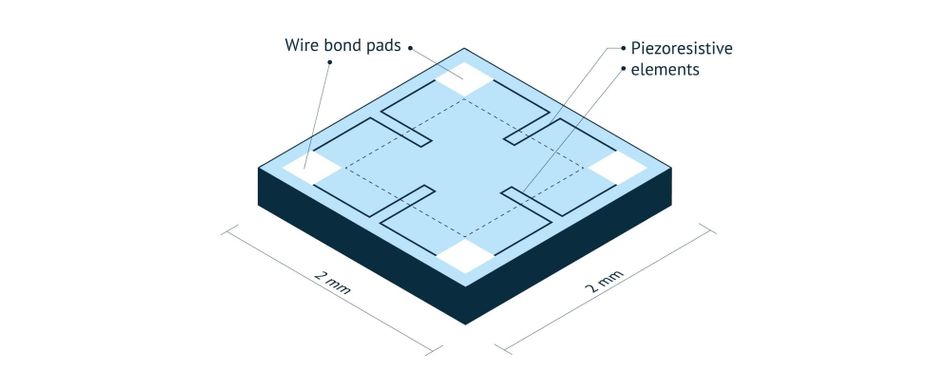
The base structure of a typical piezoresistive pressure sensor is a planar silicon diaphragm formed by chemical or dry etching. Piezoresistors are placed near the edge of the membrane, within the sensor’s linear operating range (Fig 2).
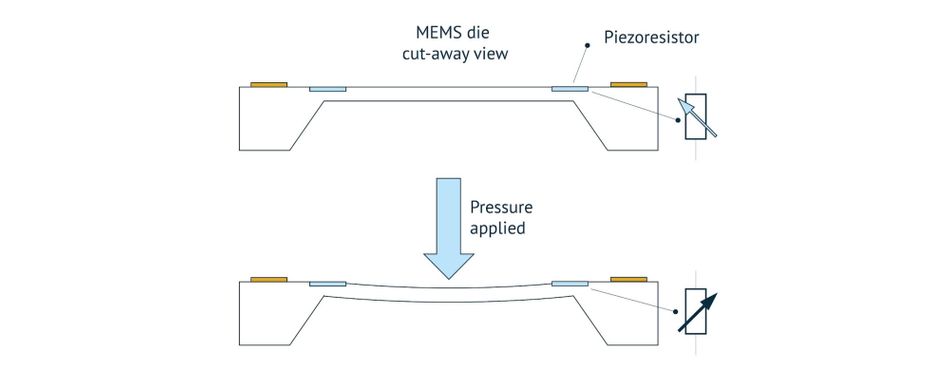
When applying pressure to the MEMS element, it deflects much like a trampoline (Fig 3). The deflection causes a strain in the piezoresistive elements, which change their resistance value in proportion to the deflection.
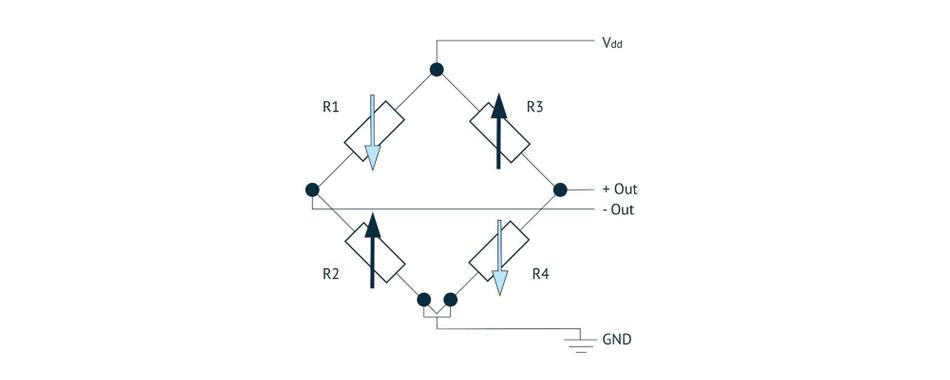
In practice, four piezoresistors are used, arranged in a Wheatstone bridge configuration, to maximize signal levels and provide a degree of common-mode rejection to undesirable noise (Fig 4).
Corrosion from aggressive chemicals can affect how the piezoresistive components, interconnects, and wire bond pads function. One way to detect problems with the sensor is to look at the output signal offsets with no pressure applied. If operating correctly, the differential output should be roughly equal to 0V. If the output is drastically far from 0V, it’s an indication of a problem with the sensing element. In a similar way, other environmental factors like the ones explained in the previous section of this article, can introduce offsets in the output signal and generate erroneous data from the sensor.
The MEMS sensor element signal is connected to a Complementary Metal Oxide Semiconductor (CMOS) Application-Specific Integrated Circuit (ASIC), where it is compensated for temperature linearity and other errors, then amplified and digitized. This digital data is then formatted for accessible communication to a master microprocessor via Inter-Integrated Circuit (I2C) or Serial Peripheral Interface (SPI) protocol.
Packaging MEMS Pressure Sensors for Protection
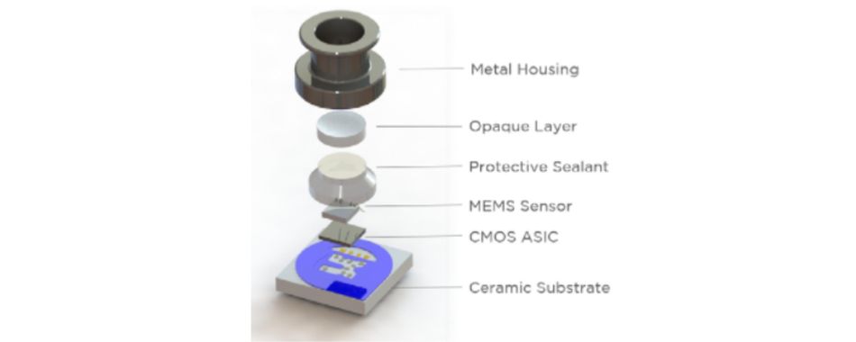
Packaging and environmental isolation of the MEMS sensing element and the CMOS ASIC is essential for the pressure sensor’s reliable functionality. Packagings protect the chip and, at the same time, allow connectivity to the outside world. While designing the package, it is important to note that all sensors must be physically in contact with the medium or phenomenon they are measuring. Also, they must be connected to the electronic system that conditions the data provided by the sensor and passes it on to the system the module is interfaced with (Fig. 5).
Sensing technologies proven in harsh environments by TE Connectivity
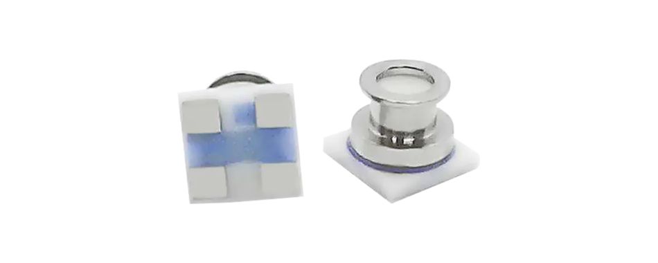
TE Connectivity has developed miniaturized pressure sensors, MS5839-02BA, suitable for exposure to harsh and corrosive environments, including strong oxidizers such as halogens (Fluorine [F], Chlorine [C]), Bromine [Br], and Iodine [I]). These types of harsh environments exist in automotive, medical, and personal wearables markets.
Chlorinated water in swimming pools presents a similar -problem for wearables applications. TE’s pressure sensors can be used as altimeters for sports watches used by triathletes or depth sensors in dive computers. Without appropriate device packaging and protection, the sensors can corrode and fail when used in swimming pools or seawater, both rich in dissolved or ionic chlorine.
Testing and Validation of the Performance
Technology and designs developed by TE Connectivity have been tested with the sensor package exposed to saltwater, chlorine water, and diiodomethane (Methylene Iodide, MI) gas. Diiodomethane exposure is known to be the harshest test by far, for testing sensors for harsh environments.
The figures below illustrate the drift in signal output of the sensing element under the influence of diiodomethane and chlorine water. Additionally, the drift in offset can mainly be explained through the presence of the humid environment rather than the diiodomethane in it. Another accelerated life test, at 85°C and in 85% Relative Humidity (RH), showed the same drifts in offset and span, as plotted alongside the diiodomethane results. Here are the steps followed for performing the tests:
Chlorine test procedure:
Samples fully submerged in a chlorine solution at 60°C for 6 hours
Then dried in a temperature/humidity chamber at 60°C and 60% RH for 18 hours
Testing is done, and data is recorded
Steps 1–3 are repeated until 40 cycles are completed
Steps 1–4 are repeated by increasing levels of chlorine concentration (from 20ppm to 100ppm)
Samples are compared with standard packaged sensors (not enhanced for harsh media).
Diiodomethane test procedure:
Test Conditions and Procedure:
Samples are placed in a chamber with the following conditions:
95% RH
85°C constant temperature
Samples tested at 48, 170, 300, and 500 hours
Samples are then compared with standard packaged sensors, not enhanced for harsh media.
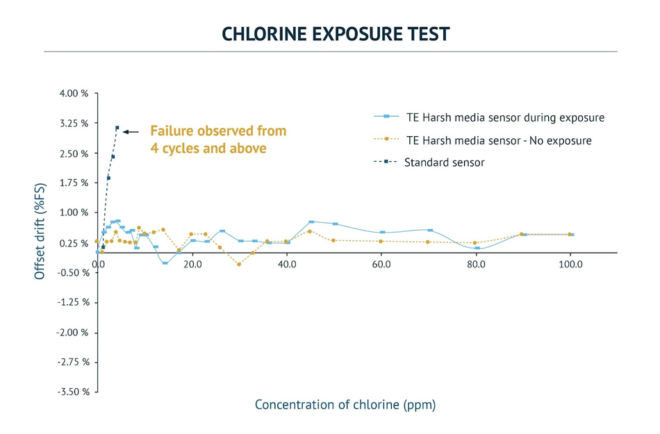
As evident from the above graph that showcases the effect of increasing concentration of chlorine on the offset drift, ordinary sensors fail quickly and produce an inaccuracy of over 3% of Full-Scale Deflection (FSD) during measurement, which is unacceptable for commercial use. On the other hand, the performance of TE’s pressure sensor MS5839-02BA remains well under 1% even for extreme levels of exposure.
TE Connectivity’s portfolio of sensors for harsh environments
TE Connectivity's MS5839-02BA pressure and humidity sensor is optimized for space-constrained altimeter applications in wearables, drones, computers, and more. The module consumes low power and can operate in a wide range of pressure and temperature ranges. The sensor also comes with a high-speed analog-to-digital converter (ADC) to make recording readings quick.
TE Connectivity’s package design and assembly procedures provide a sensor with enhanced resistance to corrosive chemicals and atmospheres. These design and assembly procedures provide customers with added confidence that TE sensors will resist failure or malfunction in applications in corrosive environments.
Conclusion
Adopting sensors specially designed for harsh environments can help systems engineers to design systems with maximum reliability and safety while reducing operating costs. Cutting-edge offerings like predictive maintenance can be enabled only with the help of sophisticated sensing technologies. It is interesting to note how various trends like miniaturization, sensor fusion, and the ability to withstand harsh environments all shape the future of sensors.
This article was initially published by Mouser and Amphenol in an e-magazine. It has been substantially edited by the Wevolver team and Electrical Engineer Ravi Y Rao. It's the fifth article of a 6-part series examining Connectivity and Sensing Technologies for Harsh Environments. Future articles will introduce readers to some more interesting applications of the technologies in various industries.
- The introductory article provided an overview of the different harsh environments that electronic circuits and systems are put through.
- The first article showcased how improvements in connectors, terminals, splices, relays, and heat shrink tubing enable connected applications
- The second article was focused on some key trends and design considerations for automotive connectivity systems.
- The third article presented three case studies on how connectors and terminals enable massive power handling in offshore installations.
- The fourth article shifted the focus back to the transport industry to explain the necessity of reliable connectors that withstand harsh environments.
- The fifth article was about the theory of sensor design for harsh environments.
- The final article examined the principles, design, manufacturing, and applications of heat shrink cable accessories in depth.
About the sponsor: Mouser Electronics
Mouser Electronics is a worldwide leading authorized distributor of semiconductors and electronic components for over 1,100 manufacturer brands. They specialize in the rapid introduction of new products and technologies for design engineers and buyers. Their extensive product offering includes semiconductors, interconnects, passives, and electromechanical components.

References
[1] TE Connectivity MS5839-02BA Digital Pressure & Temperature Sensors, Mouser Electronics, [Online], Available from: https://www.mouser.com/new/te-connectivity/te-ms5839-02ba-sensors/