Impact of Post-Processing on Dimensional Accuracy of Parts
This article will discuss the different post-processing methods and their impact on dimensional accuracy, helping you navigate potential challenges and ensuring your designs achieve the precision and quality they require.
13 Nov, 2024. 5 minutes read
This article was first published on
xometry.proIn traditional manufacturing and additive manufacturing, the design and production phases are often the main focus. However, end products, whether they are industrial machines or electronic devices, often require post-processing to enhance their appearance or durability characteristics.
Post-processing in traditional manufacturing includes machining, polishing, and coating to smooth surfaces, remove excess material, or apply protective finishes. Additive manufacturing employs specific methods like support removal, surface smoothing, spray painting, and curing. For instance, resin 3D prints require UV light or heat post-curing to solidify and enhance their mechanical properties.
But what impact does post-processing have on the dimensional accuracy of parts? Will the part expand or contract? These are critical questions to consider when creating a 3D model to ensure that the part meets design specifications, functions correctly, and fits together seamlessly.
Common Post-Processing Techniques in Manufacturing
In designing, post-processing is important since it enhances part aesthetics as well as functionality. This also implies that it affects dimensional accuracy. There are several typical post-processing methods which are employed in CNC machining, sheet metal fabrication, and 3D printing:
- Bead blasting: This technique uses a high-pressure stream of small beads, often made from glass or plastic, directed at the surface of the part, removing any faults it has and making it even all over. The process can smooth sharp edges slightly, thereby possibly changing key dimensions, particularly where intricate detail abounds.
- Electropolishing: This is an electrochemical method that removes very thin layers from steel, ensuring shiny surfaces after cleaning. However, the removal process produces bluntness, and results in minimal adjustments to fit precision requirements due to dimension changes.
- Vapor smoothing: Vapor smoothing involves bringing objects created from 3D printing in contact with chemical vapors, resulting in melting and regulating the outer surfaces. This process may alter small features and round off sharp edges, particularly for finely detailed parts.
- Media tumbling: In addition to burr removal, media tumbling also polishes surfaces through placing them into vibratory containers fitted with abrasive media. This process is not suitable for fragile part features like sharp edges.
- Sandblasting: Sandblasting uses high-speed particles for cleaning surfaces as well as texturing prior to painting or other treatments.
- Powder coating: Here, dry powders are applied electrostatically onto an object that will then be heated to cure the coat into a long-lasting one. However, the process increases dimensions slightly and may cause trouble in fitting tight components together.
- Plating: Plating involves depositing a metallic coating onto a surface to enhance electrical conductivity, wear resistance, and corrosion protection.
- Anodizing: Anodizing, which comes in different types (Type II and Type III being the most commonly used), is an electrochemical process used for increasing the oxide layer on metal surfaces.
- Passivation: This is the process by which stainless steel parts are treated to remove free iron and obtain better resistance to corrosion through the formation of a protective oxide layer.
- Spray painting: This process is used to apply paint to parts for aesthetics and protection, potentially altering dimensions slightly.
Some post-processing methods can be combined for enhanced results, such as vapor smoothing followed by spray painting to achieve a smooth, colored surface, or sandblasting followed by anodizing for a matte, corrosion-resistant finish.
How Different Post-processing Techniques Impact Dimensional Accuracy
When considering post-processing for parts, it is important to understand how each technique impacts both dimensional accuracy and surface finish. The table below compares different post-processing methods (all available on Xometry’s Instant Quoting Engine®), including their effects on the material’s dimensional accuracy and the typical surface finish you can expect.
| Technique | Dimensional Change | Surface Finish | Typical Applications | Materials They Work With |
|---|---|---|---|---|
| Bead Blasting | Negligible | Matte/satin, grainy | Aesthetic finishing, surface preparation for coatings | Metals, plastics, composites |
| Electropolishing | Slight reduction (0.00635 mm) | Bright, smooth | Improving corrosion resistance and smoothing out micro-peaks and valleys | Stainless steel, aluminium, copper |
| Vapor Smoothing | Minor reduction (~0.023 mm) | Glossy, smooth | Enhancing surface quality of 3D printed parts | Thermoplastics |
| Media Tumbling | Negligible | Satin-like finish | Parts with smoothed surface | Metals, plastics |
| Sand Blasting | Slight reduction (~0.005–0.025 mm) | Dull finish | Surface preparation for paint | Metals, plastics |
| Powder Coating | Addition (~0.02–0.05 mm) | Matte or glossy, colored | Wear-resistant parts, aesthetics | Metals, plastics |
| Plating | Addition (~0.005–0.025 mm) | Metallic finish | Electrical components, wear-resistant parts | Metals (e.g., copper, nickel) |
| Passivation | Negligible | Matte, enhanced resistance | Aesthetic enhancements, surface protection | Stainless steel |
| Spray Painting | Addition (~0.02–0.1 mm) | Smooth, colored | Surface enhancement and protection | Metals, plastics |
| Anodizing (Type II) | Addition (~0.0025 mm) | Matte or glossy, colored | Corrosion resistance, durable parts | Aluminium |
| Anodizing (Type III) | Addition (~0.025 mm) | Matte or slightly rough, colored | High-wear applications, mechanical components, corrosion resistance, durable parts | Aluminium |
| Spray painting and vapor polishing | Addition (~0.012–0.25 mm); slight reduction (negligible) | Smooth, colored; Glossy, smooth | Combining surface enhancement/protection and quality improvement for 3D printed parts | Thermoplastic |
| Sand blasting and anodizing | Negligible reduction (~0.0025–0.025 mm) | Matte or satin, grainy; Matte or glossy, colored | Surface preparation and protection for aluminium parts | Aluminum |
Regulations and Standards for Maintaining Dimensional Accuracy During Post-processing
Here is a brief overview of standards related to dimensional accuracy maintenance during post-processing commonly used in Europe, the UK and Turkey:
| Standard | Usage | Objective | Example of Application |
|---|---|---|---|
| ISO 2768 | Establishes general tolerances for linear dimensions, angular dimensions, and geometrical tolerances in unassociated metal parts | Ensures consistency in size throughout different manufacturing processes and post-production stages | Indicating medium tolerances for a CNC-machined metal shaft with a 50 mm diameter as “ISO 2768-m” on the drawing |
| ISO 1101 | Sets permissible limits for variations in part geometry, focusing on form and position tolerances | Ensures components meet geometric standards despite dimensional changes during finishing operations | Specifying perpendicularity: ⊥ 0.1 ISO 1101 for a hole to remain within a 0.1 mm tolerance zone relative to a given datum plane |
| ASME Y14.5 | Describes how GD&T symbols specify allowable variations in sizes and shapes of parts using controls such as position control | Ensures uniformity and high accuracy during and after manufacturing | Using positional tolerance symbol on the drawing: Position: Ⓟ 0.2 | ⌀10 | A B C* |
| ASTM D618 | Describes the practice for conditioning plastics for testing purposes after molding to test for thermal or chemical smoothing effects | Ensures dimensional accuracy by conditioning samples for equilibrium before further operations | Conditioning plastic samples for 48 hours at 50°C, then 96 hours at 23°C with 50% relative humidity before chemical smoothing |
*The center of the hole must fall within a zone of 0.2mm diameter about datums ‘A,’ ‘B,’ and ‘C’ so that accurate assembly can be achieved during post-processing.
Tools and Technology for Monitoring and Controlling Dimensional Changes
Monitoring/controlling dimensional changes during post-processing requires accurate tools/technologies. Some key solutions include:
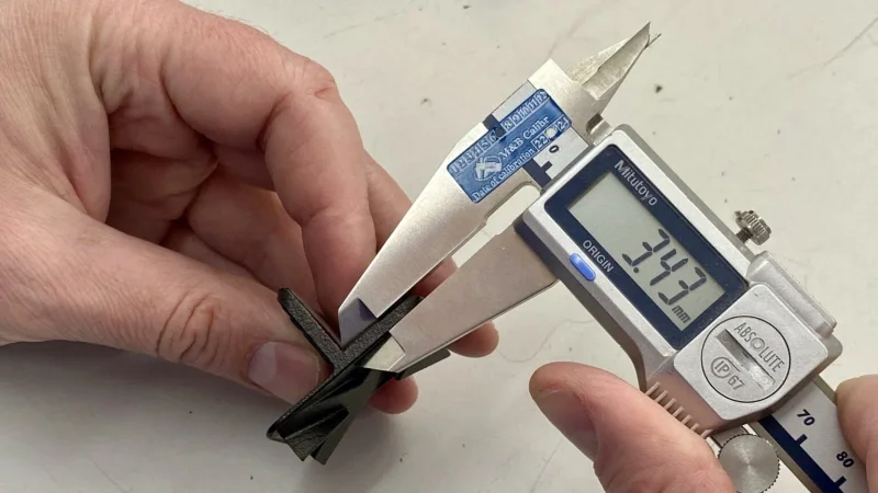
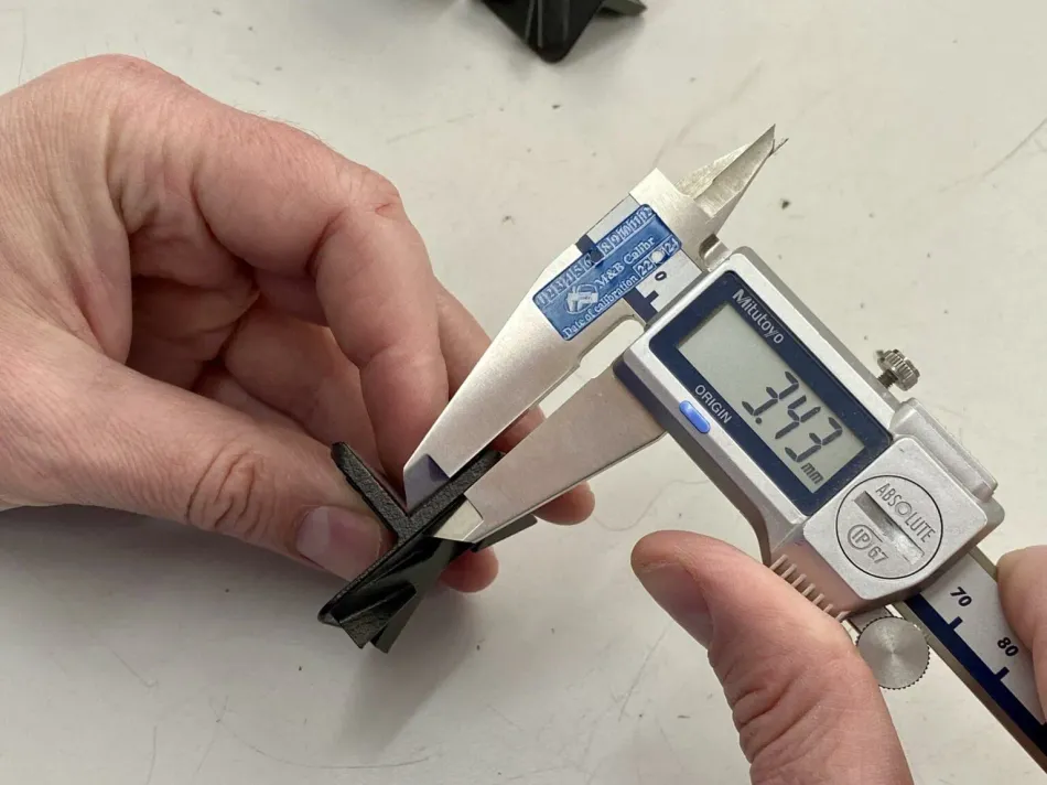
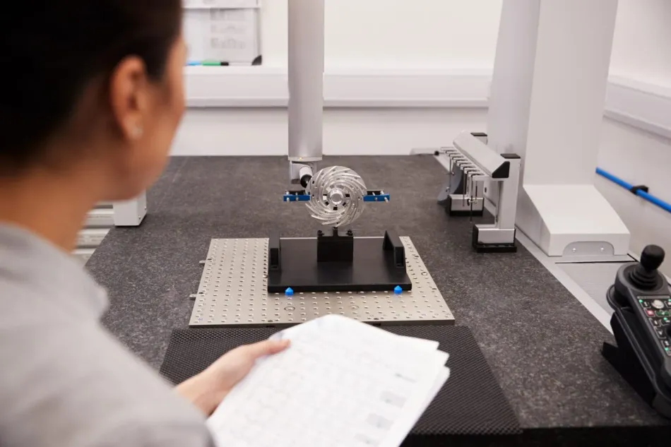
- Coordinate Measuring Machines (CMMs): These machines use a probe to accurately measure the physical shapes of an object. They are useful for checking measurements as well as detecting any deviation from design specifications. They excel in precision, often achieving measurements within micrometers (0.001 mm), far surpassing the typical accuracy of digital calipers, which is around 0.01 mm.
- Laser scanners: Laser scanners provide non-contact measurement. They generate high-resolution 3D models of parts that are then compared to CAD designs to ascertain any dimensional change.
- Optical comparators: These devices project the profile of a part onto a screen and allow for visual comparison against pre-set standards. They are most useful in monitoring dimensional changes in small and intricate parts.
- Digital calipers and micrometers: For fast, accurate measurements, digital calipers and micrometers provide excellent accuracy when it comes to measuring lengths or thicknesses, which is imperative for quality control.
- Surface roughness testers: These determine surface finish quality by identifying changes that would affect dimensional accuracy resulting from practices like sanding or polishing through post-processing.
How to Reflect Tolerances on Technical Drawings
- To reflect the finishing processes, such as anodizing, on technical drawings, it is necessary to indicate post-treatment tolerances for any specific customer requirement (e.g. hard anodizing 50µm).
- Clearly specify on the drawing that tolerances on the drawing are post-treatment.
- For thin treatments (<10 µm), final tolerances can often be assured. For any treatments thicker than 10 µm, it is recommended to mask certain surfaces to prevent unpredictable dimensional changes post-treatment (e.g. mask threaded holes to ensure they remain within tolerance and functional after a thick anodizing layer is applied).
- Add any surface finish symbols (roughness) and specific tolerances (linear or geometric) that will ensure the part meets its functional requirements.