How to Calibrate a 3D Printer: A Comprehensive Guide for Engineers
A thorough tutorial for digital design engineers, hardware engineers, and electronics students on how to calibrate a 3D printer effectively. It covers theory and practical implementations.

10 Mar, 2026. 17 minutes read
Calibration is the foundation of reliable FFF/FDM printing. If you want accurate, repeatable parts, understanding how to calibrate a 3D printer is key. Unlike casual hobby printing where small imperfections may be acceptable, engineers and product designers depend on dimensional precision so printed parts fit into assemblies, housings, and electronic enclosures. Even minor errors in extrusion or motion can lead to misaligned components, stressed fasteners, or clearance issues that compromise functionality.
This article presents a structured calibration framework for FDM printers. It begins with foundational adjustments such as bed leveling and extruder calibration, then progresses to flow rate tuning and accurate filament measurement. From there, it addresses motion-system parameters including belt tension, axis steps, retraction behavior, temperature control (PID), acceleration, and jerk. Alongside practical procedures, the guide explains why each calibration step matters and highlights common pitfalls. The goal is to help users produce dimensionally accurate, mechanically reliable, and repeatable prints.
Why 3D Printer Calibration Matters
FDM printers extrude molten thermoplastic through a nozzle while moving along X, Y, and Z axes. The extruder stepper motor advances filament in discrete increments. Mechanical components—belts, pulleys, lead screws, and linear guides—translate commands into motion, while thermal elements—hotend and heated bed—maintain consistent temperatures.
Any deviation in these subsystems manifests as inaccurate dimensions, poor layer adhesion, or surface defects. Calibrating ensures that commanded movements correspond to the equivalent physical movement and that the correct amount of material is deposited.
Calibration Sequence
Calibration works best when done in a logical sequence, because many adjustments build on earlier ones. For example, tuning flow rate before setting the correct extrusion steps can lead to misleading results. In practice, each calibration step establishes a baseline that makes the next one more reliable.
The recommended order is:
Bed leveling and first‑layer calibration: Ensure the nozzle height and bed plane are correct.
Extruder calibration (E‑steps): Ensure the motor pushes the exact length of filament commanded.
Flow rate and filament diameter: Fine‑tune extrusion volume based on actual filament size.
Motion system: Adjust belt tension, verify axis steps (dimensional accuracy), and correct skew.
Retraction: Minimize stringing and oozing during travel moves.
PID tuning: Stabilize hotend and bed temperatures.
Acceleration and jerk: Balance speed and surface quality.
Bed Leveling and First-Layer Calibration
Accurate first layers are the foundation of dimensional accuracy in FDM printing. Before tuning flow rates, motion settings, or temperatures, the printer must establish a consistent distance between the nozzle and the build surface. Proper bed leveling and Z-offset calibration ensure that the first layer adheres correctly and maintains uniform thickness across the entire print area.
Manual Bed Leveling
Most entry-level printers use four spring-loaded knobs under the build plate. Proper leveling ensures the nozzle remains a consistent distance from the bed, producing a uniform first layer.
A typical workflow is as follows:
Preheat the nozzle and bed to the temperatures used for your filament to account for thermal expansion.
Home all axes using the printer’s control interface. (Navigate to an option like Auto Home or Home All.) The printer will automatically move the X, Y, and Z axes until they contact their endstop switches or sensors, establishing a precise reference position (0,0,0). Then disable the stepper motors so the print head can move freely.
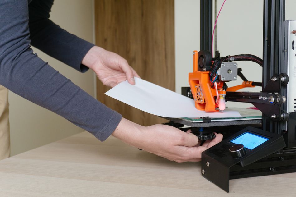
Place a sheet of paper (≈0.1 mm thick) between the nozzle and bed at one corner. Adjust the knob until the paper moves with slight resistance—neither scraping nor sliding freely.
Repeat for each corner, and then check the bed center.
Iterate the adjustments until all points provide similar resistance.
Many guides recommend rechecking the center after adjusting the corners because the springs can shift slightly when other knobs are turned.
Finally, print a first-layer test pattern like this one. The extruded lines should appear slightly flattened and continuous, without gaps or raised ridges. If the lines look too thin or too thick, adjust the Z-offset in small increments.
Automatic Bed Leveling
Many modern printers include an automatic leveling probe (capacitive, inductive, or mechanical). These probes measure the height of the build surface at multiple points and compensate for small variations during printing.
Automatic bed leveling (ABL) simplifies setup, but it does not eliminate the need for basic mechanical alignment. The build plate should still be reasonably flat and properly mounted. Periodically clean the bed surface and probe tip, and rerun the leveling routine after moving the printer or changing build plates.
Popular DIY printers like the Creality Ender 3 can be fitted with ABL add-ons such as the Creality CR Touch or the Antclabs BLTouch.
Mesh Bed Leveling
Mesh bed leveling extends automatic probing by sampling the surface at a grid of points and building a height map of the bed. The firmware then dynamically adjusts the Z-axis during printing to maintain consistent nozzle distance.
For example, printers such as those from Prusa Research allow users to configure mesh grids ranging from 3×3 to 7×7 points, with multiple probe measurements per location to improve accuracy.[1] Some systems also include features such as magnet compensation, which ignores readings near embedded bed magnets, and enforced Z-calibration, which automatically reruns the mesh if the probe state changes.
Higher grid densities improve accuracy but increase calibration time. Engineers typically balance these settings depending on the required precision and the size of the build area.
Z-Offset and Fine Adjustments
After leveling the bed, calibrate the Z-offset, which defines the distance between the probe trigger point and the nozzle tip.
Many printers allow live micro-adjustments (babystepping) during the first layer.[2] Begin with the manufacturer’s recommended offset and adjust in ±0.05 mm increments while observing the print.
A correctly tuned first layer should:
Adhere firmly to the build surface
Show slightly flattened extrusion lines
Avoid gaps between lines
Avoid excessive squish that causes elephant’s foot
Once dialed in, the printer can consistently produce dimensionally accurate and well-bonded prints.
Recommended reading: Calibrating Your 3D Printer's Z Offset Setting
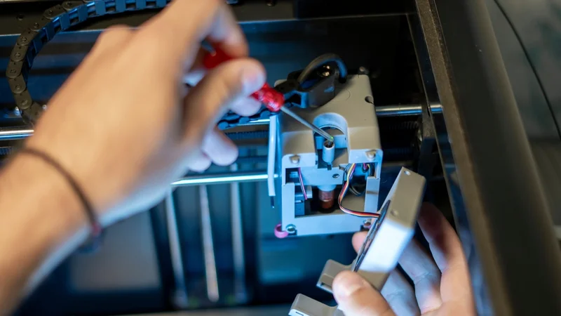
Extruder Calibration (E-Steps per mm)
If your printer feeds slightly too much or too little filament, prints can show gaps, blobs, or dimensional inaccuracies. Extruder calibration aligns the amount of filament the printer thinks it is pushing with the amount that actually enters the hotend. Once this is dialed in, other tuning steps—such as flow rate and temperature—become much more predictable.
Theory
The extruder stepper motor advances filament using a defined number of steps per millimeter (E-steps). Each step moves the filament a small, fixed distance determined by the drive gear diameter, gear ratio, and microstepping settings. Because these factors vary between machines—and can change after replacing an extruder, stepper motor, or drive gear—the correct E-steps value is not always perfectly calibrated from the factory.
If the value is incorrect, the printer will either under-extrude (leading to weak infill, gaps between lines, and poor layer bonding) or over-extrude (causing blobs, surface artifacts, and dimensional inaccuracies). Unlike flow-rate or extrusion-multiplier adjustments—which compensate for extrusion width and filament behavior—E-steps calibration focuses on the linear length of filament being fed into the hotend.
Step-by-Step Procedure
Different printers use different firmware systems. Many consumer machines use Marlin firmware, while others run Klipper, RepRapFirmware, or proprietary firmware from the manufacturer. The basic idea is the same in all cases: measure how much filament the printer extrudes and adjust the extrusion setting until it matches the commanded amount.
Check the current extrusion setting. On many printers you can see the E-steps value in the control panel or through a connected computer interface. Marlin-based printers allow users to read these settings through a console or terminal, while other firmware systems show them in configuration menus or editable config files.
Heat the hotend to the normal printing temperature for the filament you have loaded. This prevents the extruder from grinding the filament or pushing against cold plastic.
Mark the filament for measurement. Use a ruler to measure 120 mm of filament from the point where it enters the extruder, then place a clear mark on the filament with a pen or marker.
Extrude a controlled length of filament. Using the printer’s control screen or software interface, tell the printer to extrude 100 mm of filament at a slow speed.
Measure how much filament actually moved. After the extrusion finishes, measure the distance between the mark and the extruder entry point. If exactly 20 mm remains, the printer extruded the correct amount. If the remaining distance is different, the printer either over-extruded or under-extruded.
Calculate the corrected extrusion value. Multiply the current E-steps value by the commanded length (100 mm) divided by the actual length extruded. For example, if the printer’s current value is 93 steps/mm and it only extruded 95 mm, the corrected value would be approximately 97.9 steps/mm.
Update the printer setting. On Marlin printers, the new value can usually be entered through the console or saved through the control interface. On Klipper or RepRapFirmware systems, the value is typically edited in a configuration file and then reloaded.
Repeat the test to confirm the adjustment. After recalibrating, run the extrusion test again until the printer extrudes the commanded length accurately.
Typical E-steps values for printers such as Ender-3 variants often fall between 95 and 110 steps/mm. Values far outside this range may suggest mechanical issues such as slipping drive gears, worn hob teeth, or incorrect extruder gearing.
Multi-Extruder Calibration and Feed Rate
For dual- or multi-extruder printers, calibrate each extruder separately, since gearing and tension can differ between tools.
Once E-steps are set, further tuning may include adjusting extruder tension so the filament is gripped consistently and refining the extrusion multiplier (flow rate) in the slicer. When printing flexible filaments, slower extrusion speeds help prevent filament buckling and feeding problems.
Recommended reading: E-Step Calibration: How and When To Do It
Flow Rate and Filament Diameter
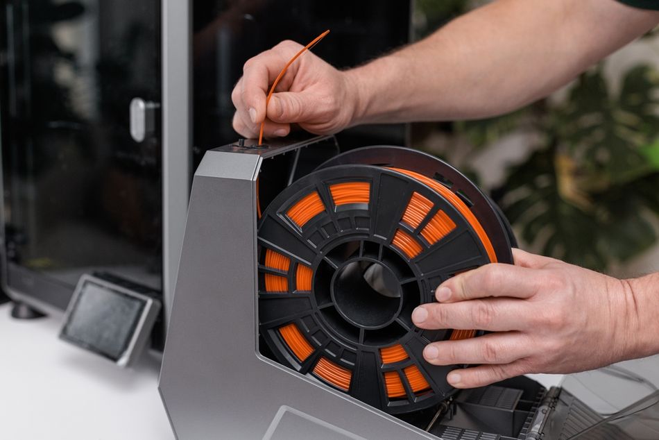
After calibrating the extruder, the next step is ensuring the printer deposits the correct volume of plastic. Even if the extruder pushes the right length of filament, small variations in filament diameter or extrusion settings can change how much material actually comes out of the nozzle. Measuring filament diameter and calibrating flow rate helps tighten dimensional accuracy and produce cleaner surfaces.
Measuring Filament Diameter
Although filament is sold as 1.75 mm or 2.85 mm, the real diameter varies slightly along the spool. Measuring the filament and entering an accurate value in the slicer improves extrusion consistency.
A common approach is to measure five points spaced about 10 cm apart using a digital caliper. High-quality filament typically varies less than ±0.02 mm, while cheaper filament may vary closer to ±0.05 mm. When measuring, avoid squeezing the filament with the caliper jaws; use light pressure and keep the filament straight.
Average the measurements and enter the value—usually to two decimal places—into your slicer’s filament diameter setting. In slicers such as Ultimaker Cura, PrusaSlicer, or Simplify3D, this field is typically located in the filament or machine settings.
Flow Rate (Extrusion Multiplier) Calibration
Flow rate—often called the extrusion multiplier—fine-tunes how much plastic is deposited during printing after E-steps have been calibrated. The usual approach is to print a simple test object and compare its wall thickness with the expected value.
Print a hollow calibration cube like this one with no infill, two perimeters, and a typical layer height such as 0.2 mm. Use the same speed and temperature you normally print with.
Measure the wall thickness at several points using calipers. With a 0.4 mm nozzle, two walls should ideally measure 0.8 mm.
If the measurement differs, calculate a corrected flow rate using: New flow = Desired wall thickness ÷ Measured wall thickness.
Enter the new value in your slicer—for example the Flow percentage in Cura or the Extrusion Multiplier in PrusaSlicer.
Repeat the test print until the measured wall thickness closely matches the expected value. A tolerance of about ±0.05 mm is generally acceptable.
Dialing in flow rate improves dimensional accuracy, reduces gaps in top layers, and helps produce stronger, more consistent parts.
Belt Tension and Motion System Calibration
Once extrusion is calibrated, attention shifts to the printer’s motion system. The X- and Y-axis belts translate motor rotation into precise linear movement. If belts are too loose, prints can show ghosting or layer shifts; if they are too tight, friction increases and components wear faster.[3] A quick tension check can often resolve surface artifacts or dimensional drift.
Importance of Belt Tension
Loose belts allow small positional errors during rapid movements. This often appears as ghosting—faint ripples that echo around sharp corners—or as slight dimensional distortion. Belts that are overtightened, on the other hand, increase resistance on the motion system and may accelerate bearing or motor wear.
Common warning signs include large belt deflection, dull sounds when the belt is plucked, or visible fraying along the belt edges.
Checking Belt Tension
Several quick checks can indicate whether belt tension is within a reasonable range:
Deflection test: Press the belt at its midpoint. A typical belt should deflect roughly 1 mm for every 60–70 mm of belt length.
Pluck test: Pluck the belt like a guitar string. A low, clear note usually indicates good tension, while a dull thud suggests the belt is loose and a sharp ping may indicate excessive tension.
Manual glide test: With the motors disabled, slide the print head or bed by hand. Smooth motion usually means the tension is close to correct, while slack or heavy resistance suggests adjustment is needed.
Frequency tools: Some users measure belt frequency using a smartphone tuner app (such as this one from Prusa) or a printable belt gauge, typically targeting 60–90 Hz.
Adjusting Belt Tension
The exact method varies between printers, but the general process is similar.
Turn off and unplug the printer before making adjustments.
Identify the tensioning system. Many newer printers use knob-style belt tensioners, while older machines rely on brackets secured by screws.
Adjust the tension gradually. For knob tensioners, turn the knob slightly clockwise to tighten the belt. For screw-style mounts, loosen the bracket screws, pull the bracket outward to tension the belt, then tighten the screws again.
Check motion smoothness. With the motors off, move the carriage or bed across the axis to confirm that motion remains smooth and free.
Verify with a test print. Printing a calibration cube or simple test model can reveal ghosting or dimensional errors that indicate further adjustment is needed.
Routine inspection helps maintain motion accuracy. Many manufacturers recommend checking belt condition periodically, cleaning belts with a dry cloth, and replacing them if fraying or missing teeth appear.
Axis Steps and Dimensional Accuracy
Most printers ship with correctly configured X, Y, and Z steps per millimeter, so dimensional errors are more often caused by belt tension, extrusion settings, or material shrinkage rather than incorrect step values.
To verify accuracy, print a calibration object with known dimensions—ideally 50 mm or larger to reduce measurement error. Measure each axis with good calipers. If the error exceeds roughly ±0.1 mm (about 0.2%), the step values can be adjusted using the following formula:
New steps = Current steps × (Expected dimension ÷ Measured dimension)
After updating the values in firmware and saving them, print the object again to confirm the correction.
CNC Kitchen has notably cautioned against relying on small 20 mm calibration cubes, since measurement errors and slight over-extrusion can distort the result.[4] Larger test models—such as 100 mm calibration objects or designs like the CaliFlower—may provide more reliable measurements because they include multiple surfaces and reduce the influence of extrusion artifacts.
It is also common to repeat dimensional calibration for different materials. Plastics such as PLA, PETG, and ABS shrink by different amounts as they cool, which can affect final part dimensions.
Skew and Squareness
Another source of dimensional error is axis skew, which occurs when the X and Y axes are not perfectly perpendicular. This can happen if the printer frame is slightly out of square or if mechanical components are misaligned.
A simple test is to print a square object and measure its diagonals. If the diagonals differ, the axes are not perfectly square. In some firmware—such as Klipper—skew can be corrected through configuration parameters. In other cases, the printer frame or gantry may need to be mechanically squared.
Because skew interacts with other motion parameters, this adjustment is typically done after belt tension and extruder calibration have already been completed.
Recommended reading: 3D Printing VFA: Vertical Fine Artifacts and How to Control Them
Retraction Calibration
Retraction settings help control what happens when the print head moves without depositing plastic. Without retraction, molten filament can slowly ooze from the nozzle during travel moves, leaving thin strands (commonly called stringing) between printed features. Retraction works by briefly pulling filament backward inside the hotend to relieve pressure before the nozzle travels.
While retraction is technically just an aspect of slicer settings adjustment, we include it in this calibration guide because it directly affects print quality and is often tuned alongside hardware parameters during the printer setup process.
Theory of Retraction
Two settings have the largest influence on retraction behavior: retraction distance and retraction speed. Retraction distance describes how far the filament is pulled back, while retraction speed controls how quickly that movement happens.
The correct values depend largely on the extruder design. Direct-drive extruders, where the drive gear sits close to the hotend, usually require shorter distances because the filament path is short and rigid. Bowden systems, which push filament through a PTFE tube, typically require longer retraction distances to compensate for the slight compression and slack in the tube.
Typical starting ranges are:
Direct drive: 2–5 mm retraction distance
Bowden systems: 4–7 mm retraction distance
Retraction speed: 30–60 mm/s
These are only starting points. The best settings depend on the hotend design, printing temperature, and filament type.
Step-by-Step Calibration
Retraction is usually tuned with a retraction tower, a model designed to print multiple segments with slightly different settings, like this one.
Prepare the printer. Make sure the nozzle is clean and the extruder grips filament consistently. Check that Bowden tubes are fully seated and that extruder gears are not worn or clogged with debris.
Load a retraction test model. Many slicers provide calibration models, or you can download a retraction tower designed to change settings at different heights.
Start with baseline settings. Choose conservative starting values appropriate for your extruder type, such as 3 mm for direct drive or 5 mm for Bowden systems, and set retraction speed around 40 mm/s.
Print the tower and inspect it. Look for stringing between pillars and small blobs where retraction occurs.
Adjust gradually. Increase retraction distance in small increments (about 0.5 mm) or adjust speed by around 5 mm/s between tests until stringing is reduced.
Observe secondary effects. Excessive retraction can cause blobs, inconsistent extrusion, or filament grinding, so aim for the lowest setting that eliminates visible strings.
Retraction interacts with printing temperature and filament moisture. Higher temperatures increase oozing, while damp filament can cause stringing even with well-tuned retraction. If stringing persists, consider slightly lowering the printing temperature or drying the filament before continuing calibration.
Recommended reading: 3D Printer Stringing: How To Fix It
PID Tuning for Temperature Stability
Stable temperatures help keep extrusion consistent. If the hotend temperature fluctuates widely, the viscosity of molten plastic changes, which can lead to uneven extrusion and visible surface variation. Many printers therefore use PID temperature control, which continuously adjusts heater power to maintain a steady temperature rather than simply switching the heater fully on or off.
PID tuning recalculates the internal control parameters that govern how the printer stabilizes temperature. It is typically worth running after installing a new hotend, heater cartridge, thermistor, or cooling fan.
Hotend PID Tuning
Most printers provide an automatic tuning routine that heats and cools the hotend repeatedly to determine optimal control values.
A typical workflow is:
Preheat the printer and enable cooling. Heat the hotend to a moderate temperature and turn the part-cooling fan to the speed you normally use when printing. This helps the tuning process reflect real printing conditions.
Open the printer’s console or control interface. Many users do this through a USB connection using a slicer’s terminal window (such as the console in Ultimaker Cura) or a printer management interface like OctoPrint. Some printers running Marlin firmware also provide a PID autotune option in the LCD menu under configuration settings.
Start the PID autotune routine. Enter the PID autotune command and specify a target temperature close to your normal printing temperature (for example, around 200 °C for PLA or 240 °C for PETG). Once started, the printer will automatically heat and cool the hotend several times while measuring how quickly the temperature responds.
Record and apply the calculated values. At the end of the process, the printer reports three parameters—often labeled Kp, Ki, and Kd—that define the temperature control behavior. Enter these values back into the printer’s settings through the console or menu so they become the new active parameters.
Save the settings. Use the printer’s “save settings” command or menu option so the new PID values are stored in memory and remain active after restarting the printer.
Verify temperature stability. Run a short print or heat the nozzle again and observe the temperature graph in your control software. The temperature line should remain close to the target value with only small fluctuations.
Heated Bed PID Tuning
Some firmware systems also support PID tuning for the heated build plate. The process is similar: run the tuning routine at a typical bed temperature, apply the returned values, and save them to the printer’s configuration.
Bed PID tuning is especially useful on printers with large beds, where slow heating can otherwise cause large temperature swings.
Acceleration and Jerk Calibration
Motion settings such as acceleration and jerk are technically part of print tuning rather than strict hardware calibration. They are usually adjusted in the slicer or firmware to refine how the printer moves during a print. We include them here because they strongly influence surface quality and are often tuned alongside other calibration steps when setting up a printer.
Acceleration determines how quickly the printer ramps up to its target speed during movement. Jerk—sometimes replaced by junction deviation in newer firmware—controls how abruptly the printer changes direction at corners. Higher values can shorten print times but increase vibration, which often appears as ringing or ghosting around sharp edges. Lower values produce smoother surfaces but can slow printing slightly. Balancing these settings helps maintain good print quality without unnecessarily limiting speed.
Accessing and Adjusting Settings
Acceleration and jerk can usually be adjusted either through the printer’s control interface or through slicer settings that override the firmware defaults.
A typical tuning process looks like this:
Check the current motion settings in the printer’s menu or configuration file and note the baseline values.
Adjust acceleration gradually, increasing or decreasing it in small steps. Many general-purpose printers operate around 1000–3000 mm/s², while rigid CoreXY machines may run higher values.
Adjust jerk or junction deviation carefully, since aggressive values can introduce ringing or mechanical noise.
Print a ringing or vibration test model after each adjustment and inspect the surfaces for ghosting around sharp corners.
Slower machines typically benefit from more conservative motion settings, while rigid CoreXY designs often tolerate higher accelerations without introducing visible artifacts. The goal is to find a balance between print speed and surface quality without introducing vibration or skipped steps.
Conclusion
Calibrating a 3D printer is partly technical and partly hands-on. In this guide we covered the main adjustments that affect print quality: bed leveling, extruder calibration, flow rate tuning, motion system checks, retraction, PID temperature tuning, and motion settings such as acceleration and jerk. Working through these steps in a sensible order—and checking results with simple measurements—can turn even a basic consumer printer into a dependable prototyping tool. Routine upkeep also makes a difference: occasionally checking belt tension, tightening loose hardware, and recalibrating after hardware changes helps keep the machine running smoothly.
For engineers producing enclosures, fixtures, or functional prototypes, a well-calibrated printer means fewer failed prints and fewer design revisions. Parts are more likely to fit together properly the first time. In educational settings, calibration is also a useful way to illustrate ideas like mechanical tolerances, material behavior, and basic control systems. And as printers gain new features such as input shaping and more advanced bed compensation, the underlying principle remains the same: take a systematic approach, change one variable at a time, and verify the results.
Frequently Asked Questions
How often should I calibrate my 3D printer?
Perform quick checks—such as bed leveling and belt tension—every few prints. More thorough calibration is recommended after replacing hardware like the extruder, hotend, or belts, or when switching to a different material with new filament settings. Retune temperature control and retraction if you change the hotend or print temperature significantly.
Do I need to calibrate X, Y, and Z steps per mm?
Usually not. Most printers ship with accurate motion settings. Only consider adjusting them if dimensional errors exceed about 0.1 mm on prints larger than 50 mm. Before changing axis steps, calibrate the extruder and flow rate, then print a larger calibration object and measure it carefully.
Can automatic bed leveling replace manual leveling?
Not entirely. Automatic or mesh leveling helps compensate for small variations in the print bed surface, but it cannot correct large misalignment. Beginners should still manually level the bed occasionally, check that the build plate is mounted correctly, and keep the nozzle and probe clean.
Why does my printer still produce stringing after retraction tuning?
Stringing can occur even with good retraction settings if the filament is damp or the nozzle temperature is too high. As part of troubleshooting, try drying the filament, lowering the print temperature by about 5 °C, and confirming that the nozzle is clean and unobstructed.
What causes under-extrusion in 3D printing?
Under-extrusion usually occurs when the printer feeds less filament than expected. Common causes include incorrect E-steps, partially clogged nozzles, incorrect filament diameter in the slicer, or excessive print speed. Checking extrusion calibration and reviewing filament settings typically resolves the issue.
What is the difference between E-steps calibration and flow rate tuning?
E-steps calibration adjusts how far the extruder pushes filament, ensuring the commanded length matches the actual amount fed into the hotend. Flow rate tuning adjusts how much plastic is deposited during printing so the final walls and surfaces match the intended dimensions.
Do acceleration and jerk settings affect hardware wear?
Yes. Higher acceleration and jerk values can shorten print time, but they also increase vibration and mechanical stress on belts, bearings, and stepper motors. For most users, moderate values provide a good balance between speed, print quality, and long-term reliability.
What are the most common calibration mistakes beginners make?
Beginners often change too many settings at once or skip measurement steps. A better approach is to calibrate one parameter at a time—such as bed leveling, extrusion, then motion settings—while keeping the rest of the printer configuration unchanged.
How can I troubleshoot first-layer problems on the print bed?
First-layer issues usually come down to bed leveling, incorrect Z-offset, or poor bed surface preparation. Clean the print bed with isopropyl alcohol, verify the nozzle height during the first layer, and confirm that the correct bed temperature is set for the filament being used.
How do I tune PID if my firmware doesn’t support the standard autotune command?
Some firmware systems use different commands or configuration methods for temperature tuning. Check your printer’s firmware documentation to find the correct procedure and run the tuning routine through the printer’s console or control interface.
References
[1] Prusa Research. Mesh bed leveling [Internet]. Prague: Prusa Research; [cited 2026 Mar 4].
[2] Marlin Firmware. M290: Babystep [Internet]. Marlin Firmware Documentation; 2026 [cited 2026 Mar 4].
[3] Creality. 3D printer belt tension: how to tighten your belt [Internet]. Shenzhen: Creality; 2026 Feb 22 [cited 2026 Mar 4].
[4] Hermann S. Calibration cubes are bad! This is how you calibrate your 3D printer [Internet]. CNC Kitchen; 2024 Feb 18 [cited 2026 Mar 4].
in this article
1. Why 3D Printer Calibration Matters2. Bed Leveling and First-Layer Calibration3. Extruder Calibration (E-Steps per mm)4. Flow Rate and Filament Diameter5. Belt Tension and Motion System Calibration6. Retraction Calibration7. PID Tuning for Temperature Stability8. Acceleration and Jerk Calibration9. Conclusion10. Frequently Asked Questions11. References