Engineering Safe and Compliant EV On-Board Chargers with Multi-Domain Protection from TDK Electronics
EV on-board chargers require precise protection against overvoltage, overcurrent, electric shock, and thermal stress. TDK delivers dedicated solutions across these domains to enhance safety, reliability, and compliance in high-voltage automotive systems.

09 Oct, 2025. 11 minutes read
Executive Summary
As EVs become increasingly mainstream, the safety and reliability of onboard systems are under greater scrutiny. Among these, the on-board charger (OBC) plays a vital role, converting grid-supplied AC power into the regulated DC energy required to charge the vehicle’s high-voltage battery pack. Given this central function, any compromise in OBC performance or protection can pose risks to the electronics, occupants, and surrounding infrastructure.
OBCs are exposed to a wide range of electrical stresses: power surges, inrush currents, switching overshoot, short circuits, and high thermal loads during fast charging. These challenges must be addressed while meeting stringent regulatory requirements from global standards bodies such as UL and IEC. At the same time, designers must balance space, efficiency, and cost constraints in rapidly evolving EV architectures.
This whitepaper explores the four key pillars of OBC protection: overvoltage, overcurrent, electric shock, and overtemperature. It explains how TDK’s components address each domain, supporting compliance, safeguarding electronics, and enabling more robust and efficient charger designs. A complete protection circuit example is also presented to illustrate how these components work together in a real-world OBC architecture.
Introduction
On-board charger (OBC) is a critical system that converts AC power from the grid into DC power suitable for charging the vehicle’s high-voltage battery. Operating under a wide range of electrical and thermal conditions, OBCs must be designed with robust protection mechanisms to prevent component damage, ensure user safety, and meet strict regulatory standards.
This whitepaper outlines the key protection requirements in modern EV OBCs and explains how TDK’s comprehensive component portfolio addresses each challenge. It begins by introducing four essential protection categories: overvoltage, overcurrent, electric shock, and overtemperature. The following sections dive deeper into each, detailing the specific TDK products designed to mitigate those risks. A complete OBC protection circuit is also included to illustrate real-world implementation.
Types of General Protection Required
Designing a safe and reliable OBC for EVs requires a layered protection strategy. These systems are exposed to a wide range of electrical and thermal stresses, and protection mechanisms must address each with precision. The following core categories form the basis of any OBC protection architecture.
Overvoltage Protection (OV): OBCs are vulnerable to voltage transients caused by lightning strikes, grid disturbances, inductive switching, or semiconductor switching overshoot. These spikes can exceed the dielectric strength of circuit components, resulting in electrical overstress and failure. Overvoltage protection ensures that sensitive electronics are shielded from such events, preserving system integrity and preventing safety incidents.
Overcurrent Protection (OC): High inrush currents during the charging of DC link capacitors and unexpected short circuits are common challenges in EV chargers. Without appropriate current limiting, these conditions can damage components, trip protection systems, or cause thermal hazards. Overcurrent protection stabilizes operation during start-up and protects against fault-induced overloads.
Electric Shock Protection (ES): EVs operate at high voltages, making shock protection critical for both end-users and service personnel. Isolation and fast disconnection mechanisms are required to prevent human exposure to dangerous voltages during maintenance, faults, or emergency shutdowns. Effective ES protection is central to compliance with international safety standards.
Overtemperature Protection (OT): High-power operation and fast charging generate considerable thermal stress in power electronics, semiconductors, and busbars. Overtemperature protection prevents overheating by detecting abnormal thermal conditions and triggering corrective actions. This ensures safe operation and extends the lifespan of OBC components.
Each of these protection domains is governed by rigorous safety and performance standards that influence component selection, design practices, and system validation. Regulatory frameworks such as those defined by UL and IEC ensure that OBC systems perform reliably and meet the necessary safety thresholds for global automotive deployment. The table below summarizes key standards relevant to EV charging systems, connectors, power conversion units, battery storage, and low-voltage switchgear.
Table 1: List of UL and IEC Standards relevant to EV charging, connectors, power conversion, battery storage, and low-voltage switchgear.
Category | UL Standards | IEC Standards |
Charging System Standards | • UL 2202: Standard for EV charging system equipment • UL 2594: Covers EV supply equipment (EVSE), including safety features like ground fault protection and thermal monitoring • UL 9741: Outline of investigation for bidirectional EV charging systems, including vehicle-to-grid (V2G) technologies | • IEC 61851: EV conductive charging system - covers safety requirements for charging equipment and systems |
Connectors and Couplers | • UL 2251: Standard for plugs, receptacles, and couplers used in EVs • UL 2734: Covers connectors and service plugs for on-board EV charging systems | • IEC 62196: Plugs, socket-outlets, vehicle connectors, and vehicle inlets - addresses safety aspects of connectors used in EV charging |
Power Conversion and Inverters | • UL 458A: Outline of investigation for power converters/inverters used in electric land vehicles | • IEC 62477-1: Safety requirements for power electronic converter systems and equipment - specifically addresses safety for power electronics in various applications, including EVs |
Battery and Energy Storage Standards | • UL 2580: Safety standard for batteries used in EVs. It addresses risks such as electric shock, fire, and mechanical hazards • UL 1974: Covers the evaluation and repurposing of used EV batteries for secondary applications like stationary energy storage • UL 2596: Test method for evaluating the thermal and mechanical performance of battery enclosure materials during thermal runaway events | • IEC 62619: Safety requirements for secondary lithium cells and batteries for use in industrial applications • IEC 61960: Secondary lithium-ion cells and batteries for portable applications • IEC 62928: EV battery swap system - safety requirements |
Low-Voltage Switchgear and Controlgear | • UL 60947-4-1 (formerly UL508): Standard for Low-Voltage Switchgear and Controlgear, Part 4-1: Contactors and Motor-Starters | • IEC 60947-4-1: Low-voltage switchgear and control gear - Part 4-1: Contactors and motor-starters - Electromechanical contactors and motor-starters |
Overvoltage Protection
OBCs are exposed to various overvoltage threats, including lightning strikes, power grid fluctuations, and load switching events, which can introduce dangerous voltage surges. These transients pose a significant risk to input filters, rectifiers, capacitors, and downstream control electronics.
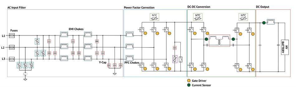
AC Input Protection
Overvoltage protection at the AC input of EV OBCs typically relies on clamping and surge diversion techniques that suppress transient energy before it can propagate further into the system. In the configuration shown, voltage-limiting components are connected from each AC line to ground, forming a common-mode protection scheme. These components remain non-conductive under normal voltage levels but switch rapidly into a low-impedance state once a surge exceeds their threshold, diverting excess energy safely to ground.
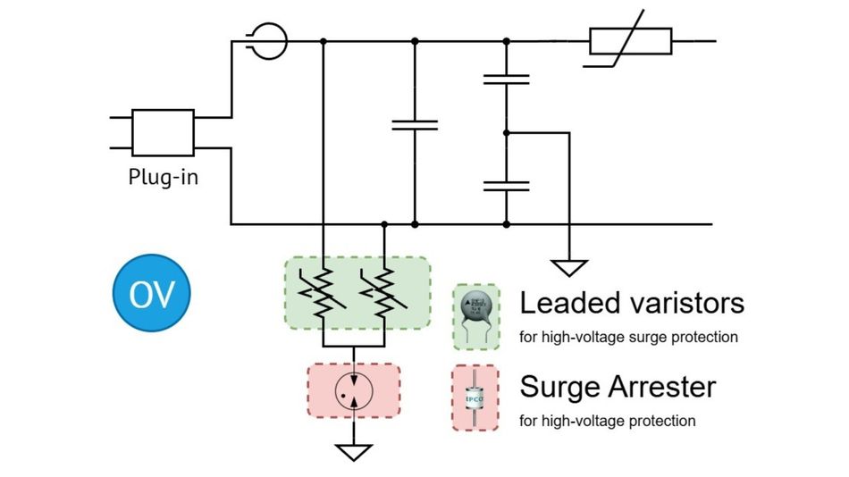
By clamping high voltages and providing a discharge path to earth, this arrangement mitigates common-mode surges and prevents dielectric breakdown, insulation failure, and stress on power components.
TDK supplies two key categories of components to implement this protection:
Leaded Disc Varistors: These components absorb and clamp high-voltage surges at the AC input, offering reliable energy dissipation and long service life. Their radial-leaded construction and high surge current capability make them ideal for line-to-ground protection.
Surge Arresters: Gas-filled arresters provide extremely fast response to transient overvoltages and are designed for high-energy events. These are commonly used alongside varistors for layered protection.
Together, these components form the first line of defense against voltage spikes entering the vehicle’s charging system.
Low-Voltage DC Protection
Downstream in the power conversion system, logic-level and low-voltage circuits are also susceptible to surge events. TDK’s multilayer varistors provide compact protection for these sensitive paths:
Multilayer Varistor Chips: Designed for board-level protection, these varistors offer low clamping voltage and fast response, making them well-suited for DC power lines, signal traces, and communication interfaces.
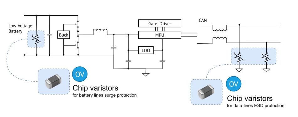
These devices help maintain signal integrity and protect downstream controllers from minor but frequent electrical disturbances.
Suppression of Switching Overshoot in Power Semiconductors
As EV systems adopt wide-bandgap (WBG) semiconductors such as SiC and GaN for faster switching and higher efficiency, managing voltage overshoot becomes critical. TDK’s CeraLink® capacitors are specifically optimized for these fast-switching environments:
CeraLink Capacitors: These capacitors offer extremely low equivalent series inductance (~3 nH) and are used as snubbers or output filters to suppress switching spikes and ringing. Available in multiple voltage ratings (up to 1300 V) and form factors, they support high-frequency operation and temperatures up to 150 °C.
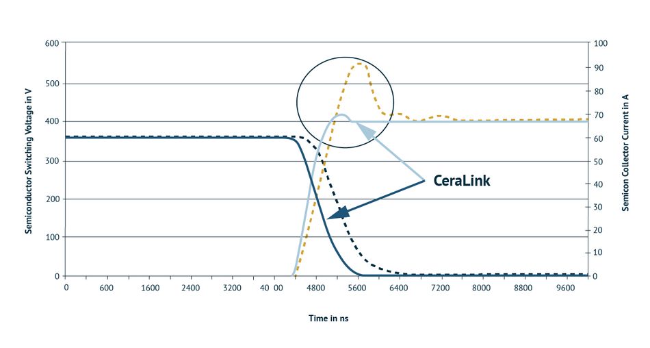
By enabling clean switching, CeraLink capacitors help reduce electromagnetic interference (EMI), increase converter efficiency, and prevent semiconductor stress - all while saving board space.
Overcurrent Protection
Overcurrent conditions in EV OBCs can occur during both expected and unexpected operating states, from the inrush current at startup to short circuits caused by component failure or line faults. Without proper mitigation, these events can lead to excessive heating, damage to power electronics, and in worst cases, fire hazards. TDK addresses these risks using self-regulating positive temperature coefficient (PTC) thermistors that act as both current limiters and safety shutoffs.
Inrush Current Limiting
When power is first applied to the OBC, the DC link capacitor bank draws a large inrush current as it charges. This surge can damage switching components, create voltage dips, or trip upstream protection devices if not properly controlled.
PTC Inrush Current Limiters (ICLs): PTC ICLs are well-suited for EV OBCs due to their compact form factor, self-resetting behavior, and ability to handle repeated power cycles. Unlike fixed resistors, which dissipate energy constantly and require external bypass mechanisms, PTC ICLs offer a dynamic resistance profile that adapts to system conditions. This behavior enables designers to eliminate mechanical relays or additional control circuitry
Key benefits include:
Self-protecting behavior
Resettable functionality
No need for mechanical bypass switches
Compact, PCB-mountable options
No external relays or control circuits
Better fault tolerance and safer thermal behavior
AEC-Q200 qualification for automotive use
Protection During Discharge or Fault Conditions
Beyond their role in inrush current limiting, PTCs contribute to fault resilience by acting as localized current bottlenecks. In high-voltage OBC designs, faults like switching device breakdown or insulation failure can propagate across power stages if not contained early. Strategically placed PTCs help create natural current boundaries, isolating the faulted region and preventing damage escalation. They also provide a degree of thermal buffering, slowing the rise in current long enough for supervisory circuits to respond. This makes them especially valuable in systems that prioritize fail-operational behavior, where selective protection is preferred over complete shutdown.
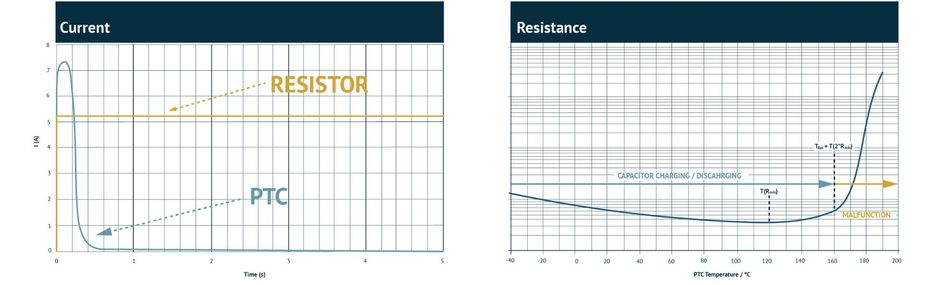
Table 2: A comparison of different options for discharge and fault protection in OBCs.
| Gold Aluminum shell resistor | Wire wound resistor | Heater shape PTC |
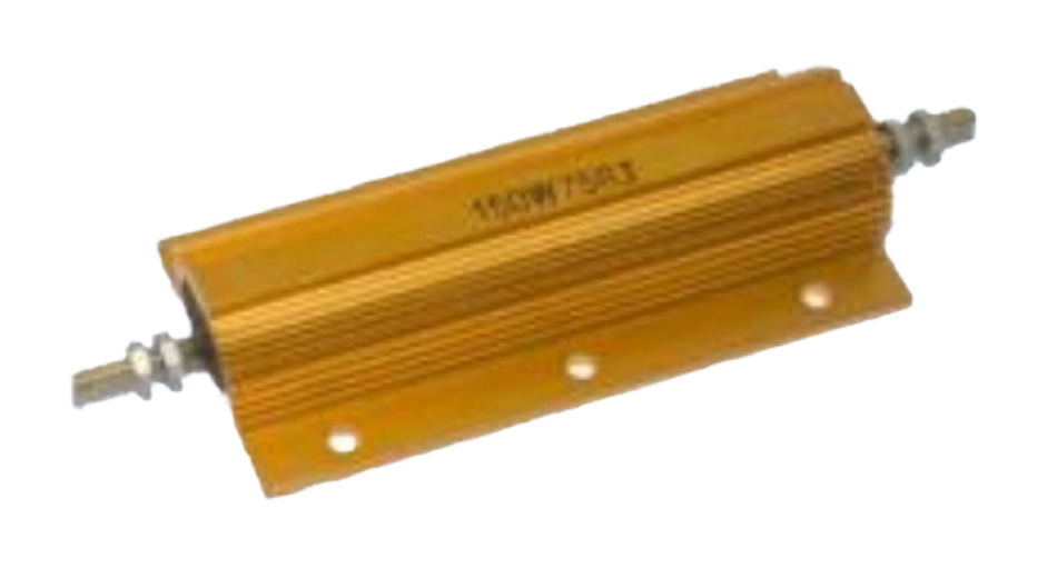 | 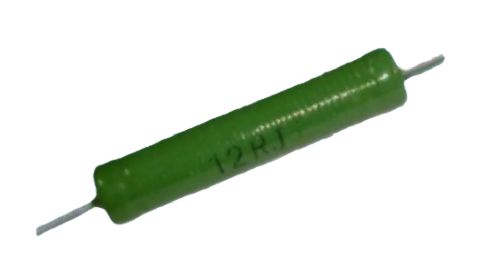 | 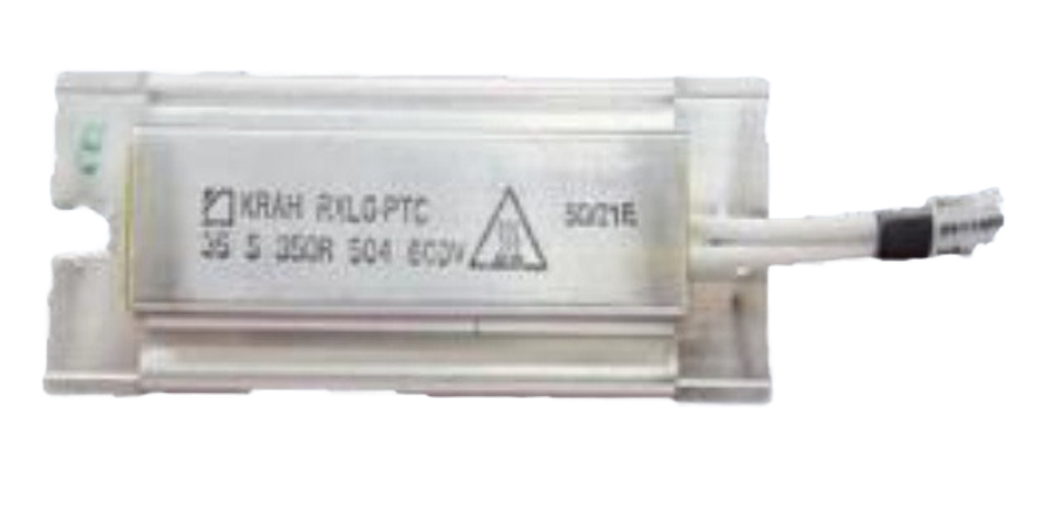 |
– Expensive – Need additional cable – Fixed resistor | + Cheap – Fixed resistor – Easily broken | – Expensive – Need additional cable |
| Leaded version PTC | Motor absorb only | TDK’s PTC ICLs |
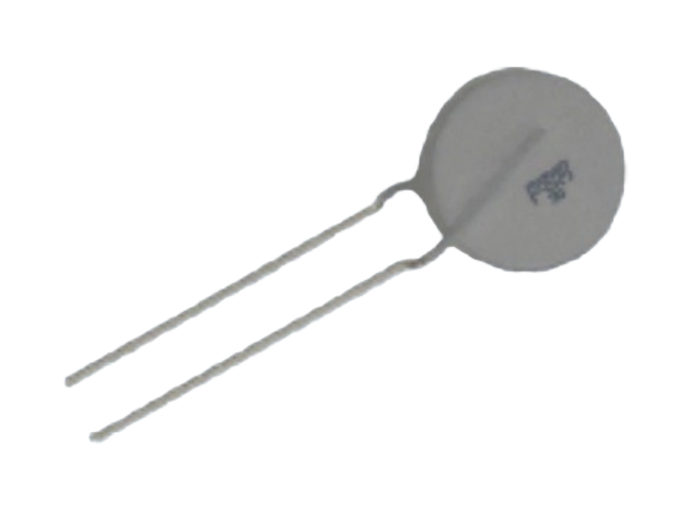 | 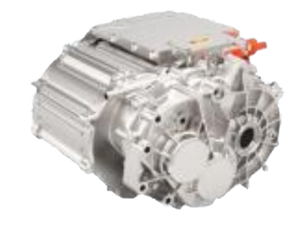 |  |
+ Cheap – Manual assembly – High height | – Function safety | +AEC-Q200 qualified +PCB-mountable, no external cabling required +Resettable resistor design +Available in SMD version +Compatible with reflow soldering +Low-profile form factor +Wide operating temperature range |
Electric Shock Protection
EVs operate at high voltages, often exceeding 400 V, with newer platforms pushing toward 800 V and beyond. These voltages, while necessary for fast charging and efficient power transfer, introduce a serious risk of electric shock to occupants, service personnel, and first responders. Effective electric shock protection ensures that high-voltage systems can be safely disconnected or isolated during faults, shutdowns, or maintenance.
TDK addresses this safety requirement through its line of automotive-grade high-voltage DC contactors, engineered for fast, reliable disconnection in harsh operating environments.
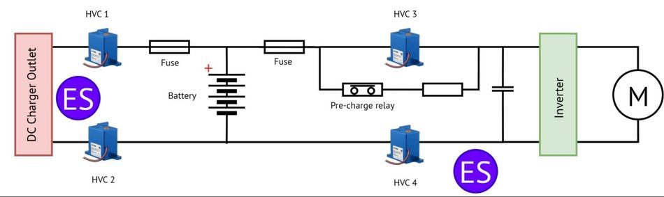
High-Voltage Battery Disconnection
High-voltage contactors serve as the primary safety switch between the battery and the powertrain or charger. In OBC architectures, they are often installed within battery junction boxes (BJBs), power distribution units (PDUs), or DC/DC converter inputs.
High Voltage Contactors: These components utilize gas-filled ceramic arc chambers that enable fast arc suppression and extended switching life. TDK’s designs support voltages up to 1000 V and continuous currents up to 500 A, with short-circuit handling capabilities over 12 kA for 5 ms.
Key features:
Bipolar design for safe disconnection of both battery poles
Hall switch-based stuck detection (in some variants)
Compact footprint for integration in tight spaces
Ready for 800 V EV systems
TDK’s HVC contactors support key OBC-adjacent functions including battery isolation, DC charging, booster switching, and integration into BJBs and PDUs. These contactors form the backbone of electric shock protection in EV systems, ensuring that faults or service events do not pose harm to people or downstream equipment.
Overtemperature Protection
Fast charging, compact layouts, and increasing power densities in EV OBCs contribute to significant thermal stress across components. Without proper thermal management, prolonged heat exposure can degrade capacitors, semiconductors, and interconnects, leading to reduced lifespan, derating, or thermal runaway in extreme cases. Overtemperature protection is therefore essential for both safety and performance.
TDK offers a range of Negative Temperature Coefficient (NTC) thermistors designed specifically for temperature monitoring in high-voltage and high-current automotive environments.
Temperature Monitoring in Power Electronics
Continuous temperature monitoring allows the system to take preventive actions, such as reducing load, adjusting cooling, or initiating controlled shutdowns, before temperatures reach dangerous levels.
NTC Thermistors: These thermistors exhibit a rapid drop in resistance as temperature rises, allowing precise sensing in real time. They are compact, accurate, and available in a variety of mounting styles (leaded, surface-mount, probe-based) to suit different thermal points within the OBC.
Key features:
Fast response time for critical thermal events
Wide operating temperature range
Automotive-grade reliability
Minimal power consumption
These sensors are typically deployed near busbars, power semiconductors, or thermal hotspots, ensuring visibility into heat buildup that might otherwise go unnoticed.
Application in High-Current Charging Scenarios
As EVs move toward ultra-fast charging (up to 350 kW and beyond), temperature rise becomes more rapid and severe. NTC sensor probes help track these changes during charge cycles, providing real-time data to the BMS or OBC controller for safe operation.
By enabling thermal feedback, TDK’s NTC thermistors enhance the predictive control of heat, reduce maintenance events, and ensure system uptime, especially under aggressive charging conditions.
Complete Circuit Protection for OBCs
While each protection domain - overvoltage, overcurrent, electric shock, and overtemperature - addresses specific risks, true reliability comes from an integrated approach. TDK’s component portfolio enables system designers to construct a fully protected OBC architecture.
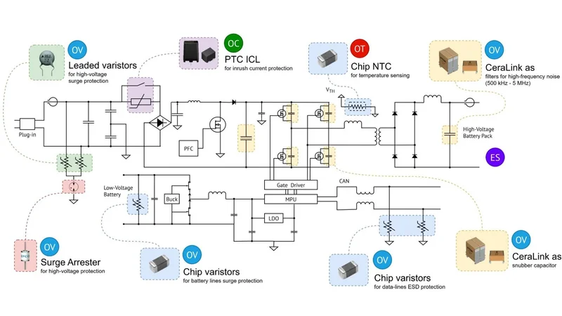
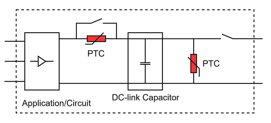
Multi-Layered Protection Across the Power Path
The diagram showcases how TDK components are strategically placed throughout the OBC to mitigate risks at every stage:
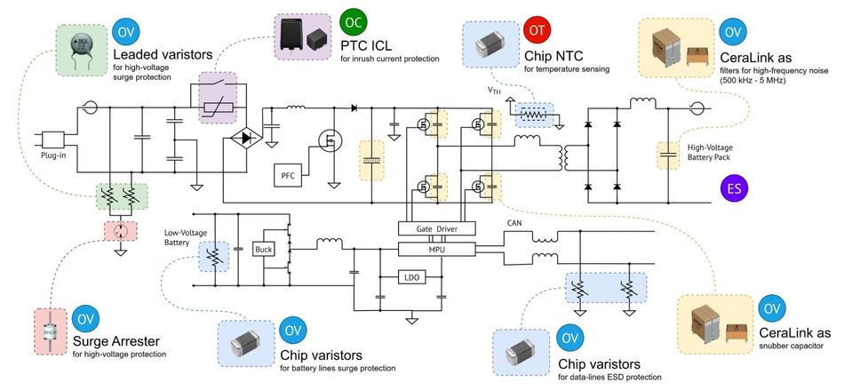
| Featured products: | Chip NTC Thermistors | Chip Varistors | Surge Arresters | Leaded Disc Varistors |
AC Input Stage
Leaded Varistors and Surge Arresters form the first layer of defense against grid-side surges and lightning strikes.
These components clamp and absorb excess voltage before it can propagate into sensitive circuits.
DC Link and Power Conversion Stage
PTC Inrush Current Limiters regulate the large inrush currents drawn by DC-link capacitors, protecting switching components and relays.
CeraLink Capacitors act as snubbers and output filters, suppressing voltage overshoot during fast switching and reducing EMI.
Low Voltage DC & Communication Lines
Multilayer Varistor Chips provide ESD and surge protection for control logic and signal interfaces.
Battery Connection and Isolation
High Voltage Contactors enable safe disconnection of high-voltage circuits during shutdowns, maintenance, or detected faults.
Thermal Monitoring
NTC thermistors track temperature in busbars, power semiconductors, and hotspot regions to enable intelligent thermal management.
Using components from a single, automotive-qualified supplier like TDK ensures compatibility, reduces sourcing complexity, and supports faster validation across the board. More importantly, it creates a cohesive safety framework that simplifies compliance with international standards.
By implementing a protection scheme as shown in the circuit reference, OEMs and Tier-1 suppliers can ensure their OBC platforms are high-performing and inherently safe.
Conclusion
The OBC is a critical subsystem in EVs, responsible not only for recharging the battery but also for ensuring safety across the vehicle’s power interface. As EV architectures grow more complex, protection requirements are expanding in scope and sophistication. Designers must address surges, inrush events, fault currents, electric shock risks, and thermal stress, often within the same compact footprint.
TDK offers one of the industry’s most complete portfolios of circuit protection components purpose-built for OBCs. From overvoltage suppression and inrush current limiting to high-voltage disconnection and thermal monitoring, each product family is engineered to support the reliability, safety, and standards compliance expected in modern EVs. These components can be integrated to form a cohesive protection framework, streamlining validation, accelerating time to market, and future-proofing vehicle platforms.
To learn more about how TDK can support your next EV design, visit the TDK Automotive Solution Center or contact your local TDK representative for application-specific support and reference designs.
Download the full whitepaper here.