Cold Solder Joint: Understanding and Prevention
A cold solder joint is a defect caused by improper melting of solder to bond PCB electronic components. This defect can impact the functionality of a PCB assembly, and so must be carefully avoided.

03 Mar, 2023. 6 minutes read

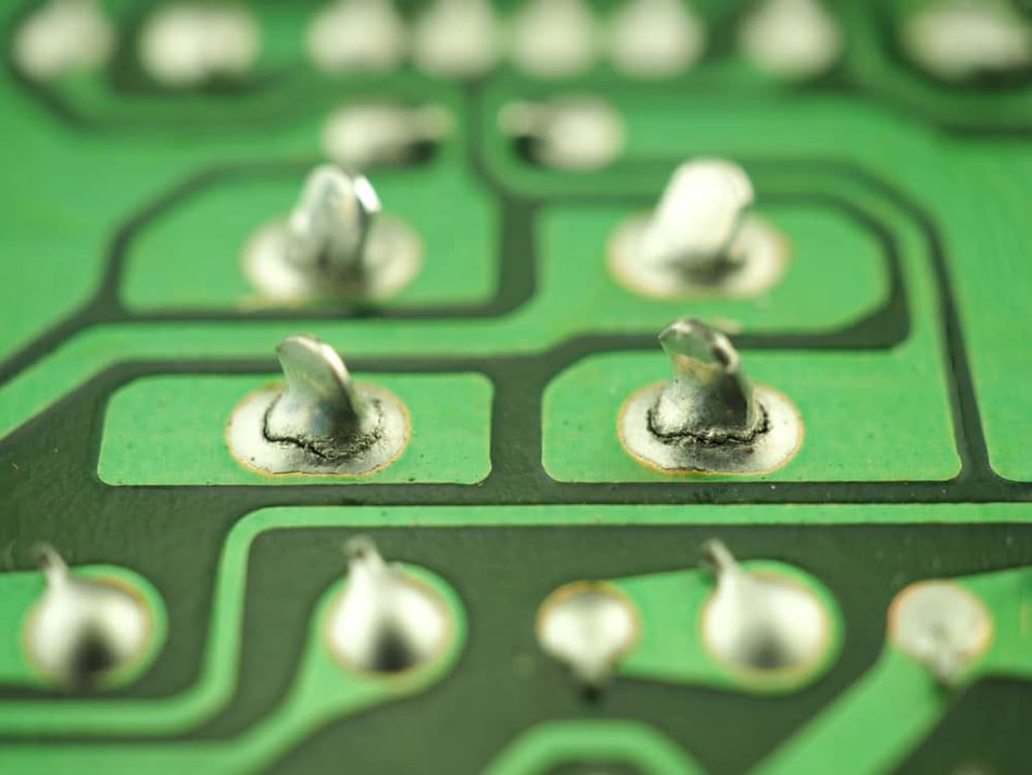
Solder Joints on Circuit Board
Introduction
Soldering involves bonding two metals together using a solder alloy. Metal in the solder bonds with metal on the printed circuit board (PCB) or component. During this process, the solder melts into fluid molten to adhere properly to the component for an excellent solder joint. When the solder does not melt sufficiently, it creates a series of reactions that results in solder joint failure. This defect is known as Cold Solder Joint.
Cold Solder Joint and Why it Should Be Avoided
A cold solder joint ensues when a solder does not melt completely, as required to form a proper joint. Characteristics of cold solder joints include a rough surface area, rigidity, and a generally uneven appearance. This defect presents a high chance for the solder joint to crack and eventually fail.
For through-hole components, the ideal solder joint should have a shiny and concave or cone-shaped appearance. The solder should be between 40 to 70 degrees slanted against the surface and the soldered pin. To execute this, the soldering iron should be heated to the peak temperature, which is typically about 15°C above the melting point of the solder alloy. After holding this temperature for at least 45 seconds, soldering can begin.
In the case of surface mount components, the pins don't stick out on the board's opposite side. This is because they go through a different soldering process, called reflow soldering. Hence, they won't form a concave shape.
Some common soldering issues leading to the formation of a cold solder joint include:
Disturbed joint: when there is a disturbance at the joint before the solder paste hardens.
Overheated joint: occurs when the solder wire does not melt properly, causing the flux on the board to be overheated.
Insufficient wetting: occurs when either the board or the pin is burned more than the other.
Cold solder joints should be avoided to maintain optimum product performance and prevent reliability problems from joint failure, in an electronic assembly. An improper joint formation can increase the electrical resistance of the joint, the effects of which will reduce the reliability of said joint. [1]
Causes of Cold Solder Joint
The primary causes of cold solder joints are explained in the following paragraphs.
Insufficient Heat
A common soldering mistake that results in a cold solder joint is not heating both surfaces at once, or not heating them sufficiently. This occurs when the soldering iron is set at a temperature that is too low or when the soldering iron is placed on the component pin for an inadequate amount of time. In this situation, reheating is required.
Another instance is when the component's pin is not being heated even when the soldering iron tip is touching and heating a pad on the circuit board. Due to this, the solder bonds to the pad on the circuit board but not to the component's pin. This can also happen the other way around, resulting in the solder bonding to the pin of the component but not to the pad of the circuit board.
Poor Cleaning
Sometimes, in moving too fast through the soldering process, and not paying attention to detail, dirt can be introduced into the solder joint. Contaminants such as grime, grease, and metal oxide may prevent a good soldered joint from taking place. It usually becomes noticeable when the solder fails to bond to dirty surfaces because it forms beads or globules. Also, the interference can make the solder take too long to wet the joint, all leading to cold solder joints.
Inadequate Solder Application
A known indicator of a weak solder condition is when there is insufficient tin in the solder spots during board tinning. There are many potential causes, but the most frequent one is insufficient heat being provided all through the process. Inadequate solder application can cause poor connection and may trigger electrical shorts. [2]
Identification of Cold Solder Joint
Cold solder joints can be detected through thorough visual checking or multimeter tests for continuity and resistance.
Visual Inspection
PCB solder joints are usually tiny; more so with the increasing reduction in board sizes. To get a good look at them, therefore, visual enhancement tools such as a magnifying lens and a spotlight are often needed. To carry out this visual inspection, the first port of call should be the color of the joints. This should be done bearing in mind that a properly dried solder joint is usually dull.
The solder joint's shape is examined next. If it is distorted or does not have the expected concave shape, insufficient heating likely prevented the solder alloy from melting completely. When resistance heats up the joint as a result, it may start to crack and eventually separate from the board. Next, check for light leakage through any joints using the torch and the magnifying glass. If light passes through any, then the joint in question was not properly bonded and therefore needs rework.
Lastly, tilt the board to check for joints that are partially loosened from the board's base. The board should also be checked for overspills, which can cause short circuits that could completely damage the board.
Testing with a Multimeter
A multimeter can be applied to check the resistance and the continuity across a PCB solder joint. This test will help to detect problems around the joint. To test for resistance, set the resistance mode of the multimeter to 1000. Connect the testing probe connectors to confirm that the tool is working correctly. Connect one testing terminal on one joint and the other terminal to a different component. The value of the reading should be zero, as long as the component is not a resistor. Anything above zero may be indicative of a cold joint.
For continuity testing, put the multimeter in continuity mode and connect the test terminals to check that the device is operational. A beep sound will confirm this. Then connect the two test terminals at either end of a solder joint. If there is no beep, there is a problem with the joint. Continuity testing checks if there is a continuous current flow from one probe to the other. A cold solder joint will break the flow. [3]
Effects of Cold Solder Joint
Cold solder joints bear extenuating effects that could impact the overall operation of a PCB. These effects majorly manifest in the electrical conductivity and mechanical stability of the joint.
Electrical Conductivity Issues
A cold solder joint that could be cracked or brittle leaves an undesirable air gap between the components. This leads to oxidation (or rust for ferrous metals), which greatly compromises electrical conductivity. It can be an intermittent or total absence of electrical conductivity, which translates to unreliability. [4]
Mechanical Instability
Cold-soldered joints are highly vulnerable to bending fatigue. Solder joints are ideally made to withstand constant vibration and movement. Therefore, improperly bonded joints are more prone to fatigue from mechanical stress, consequently leading to joint failure. Moreover, irregular temperature change can cause extensive damage to cold solder connections. In a significantly short time, the solder joint cracks and fails the circuit board.
Prevention of Cold Solder Joint
Cold solder joints can be avoided by adhering to the guidelines discussed subsequently:
Proper Cleaning of Components
It is necessary to clean surfaces and components with a general solvent to efficiently remove grease or any contaminant that could hamper the soldering process. The soldering iron is one of the primary components that should be cleaned regularly. Moreover, soldering tools should be kept in a dust and moisture-free area, to prevent contamination.
Adequate Heat Application
A cold joint happens when the applied solder does not melt completely. A good way to prevent this is by ensuring that the soldering iron is adequately pre-heated with sufficient power, to achieve optimal soldering temperature. The peak temperature should be kept at least 15°C above the alloy’s melting point for at least 45 seconds. This way, unreliable solder adhesion can be avoided.
Sufficient Amount of Solder
A sufficient amount of solder should be applied to the joint, to ensure proper bonding. Inadequate solder predisposes the joint to dryness and eventually, cracks. The solder paste must be of good quality. When applying solder, minimize any vibration or disturbances that may cause the solder paste to spread unevenly or drip onto areas it should not reach. A soldering station with a flat surface would help prevent solder flows. [5]
Conclusion
A cold solder joint is the result of an improperly executed PCB component soldering process. As discussed in this article, cold solder joints increase the electrical resistance of the solder joints, which adversely affects the reliability of the solder joints.
Thus an improperly formed joint can cause reliability problems in an electronic assembly, with regard to electrical connection, as well as mechanical stability. Cold solder joints can be easily prevented by ensuring sufficient molten solder is used with sufficient heat for the soldering iron and maintaining a dirt-free process.
References
1. Our PCB. Cold Solder Joint: A Dry or Cracked Solder Joint Caused by Improper/Incomplete Soldering. 2022. [Cited 2023 Feb 27] Available from: https://www.ourpcb.com/cold-solder-joint.html
2. PCB BUY. What Causes a Cold Solder Joint in PCB Manufacturing? 2022. [Cited 2023 Feb 27] Available from: https://www.pcbbuy.com/news/What-Causes-A-Cold-Solder-Joint-in-PCB-Manufacturing.html
3. Absolute Electronics Services. Cold Solder Joint - Definitive Guide to Soldering. 2021. [Cited 2023 Feb 27] Available from: https://absolutepcbassembly.com/cold-solder-joint-guide/
4. Soldering Irons. Cold Solder Joints. 2022. [Cited 2023 Feb 28] Available from: http://soldering-irons.com/cold-solder-joint/
5. PCBA Store. Everything You Should Know About Cold Solder Joint. 2021. [Cited 2023 Feb 28] Available from: https://www.pcbastore.com/blogs/cold-solder-joint.html