A Multi-Disciplinary Approach to Electronics Design
Electronics innovation demands seamless collaboration across disciplines. Siemens empowers teams to break down silos and accelerate product success.

24 Aug, 2026. 5 minutes read
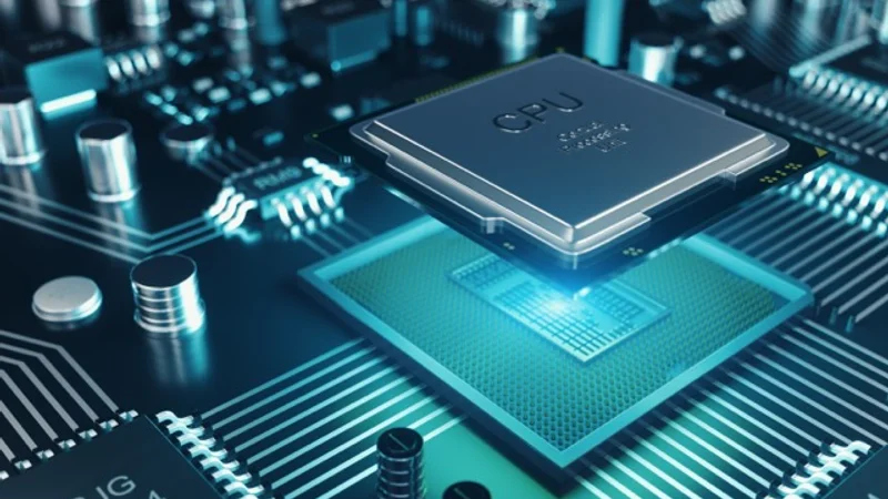
Electronic products rarely reside in a single engineering domain. Building a modern device, such as a wearable, industrial controller, or consumer appliance, requires expertly blending areas of expertise ranging from mechanical design to thermal management to embedded software. Despite this reality, many teams still develop in silos while using tools that rarely share data between teams. When those domains need to recombine late in a product program, teams often encounter expensive, time-consuming errors.
In a recent webinar, Siemens product marketing manager Greg Arnott explained how a digital thread changes the equation for new product introduction and how the Siemens Xcelerator product portfolio addresses failure modes in four major domains. Here are four key takeaways from the webinar.
Takeaway 1: The Digital Thread Is a Risk Management Strategy
A digital thread is a connected flow of data and information that spans the full product lifecycle. From early concept through simulation, manufacturing readiness, and field deployment, a true digital thread consolidates data, results, and change history into a single, accessible product record. In this way, digital threads connect the virtual models from the design stage to the physical product that eventually reaches production.

Digital threads are valuable because they surface cross-domain failures early in the product lifecycle. The earlier an error is caught, the more options engineers have to correct it at low cost, rather than letting it surface later as a costly surprise during integration testing. Since new product introductions can be fraught with risks and costs, every team building multi-domain products should view its digital thread as a risk management strategy. This reduces costly late-stage errors and accelerates time-to-market.
Takeaway 2: MCAD/eCAD Collaboration
When a board and its enclosure do not fit, the problem usually boils down to poor communication between teams caused by incompatible design tools. The conventional approach to exchanging data between mechanical CAD (MCAD) and electronic CAD (eCAD) tools gives neither team visibility into the other's engineering decisions.
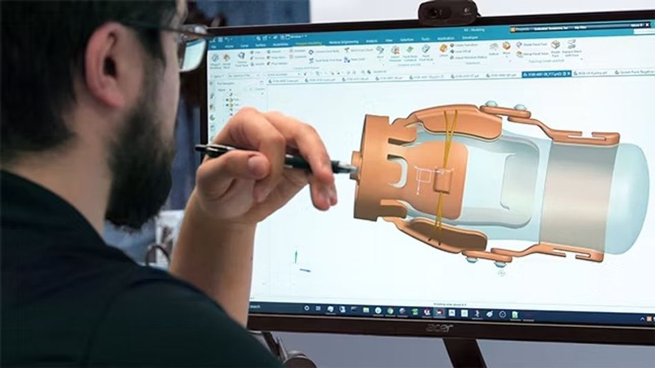
Siemens solves this problem with IDX (Incremental Data eXchange), a protocol that communicates design changes as discrete transactions rather than complete file replacements. With this approach, each stakeholder can individually preview, accept, or reject changes before merging them into the shared record, allowing all teams to advance the shared baseline in a controlled way.
Siemens has also integrated its NX CAD/CAM/CAE software suite into its Xpedition PCB design platform to bring design rule checks into the MCAD environment. The collaboration between NX and Xpedition also covers embedded components and high-density interconnect (HDI) designs, ensuring they are placed at the correct z-position for high-density packaging without sacrificing fidelity. With these tools, teams can easily work from the same rule set and catch clearance violations earlier in the design cycle.
For team members who do not hold a CAD license, Siemens offers PCB Exchange Connect, a cloud-based, CAD-agnostic application that lets users access live PCB parameters in a browser on any device. It works with ODB++, IDX, IDF, and other common formats regardless of which MCAD or eCAD tools the team uses, so anyone can visualize, query, compare, and validate PCB assemblies without design software. This enables faster collaboration and reduces the risk of costly design iterations.
Takeaway 3: Thermal Design Needs to Start Before the Enclosure Closes
As designers miniaturize devices, thermal management has become a focal point.
When more heat exists in smaller volumes, semiconductors run hotter, slow down, and fail sooner. A widely cited rule of thumb is that every 10 °C rise in junction temperature roughly halves a semiconductor's expected lifetime.
Beyond lifetime performance, thermal conditions can also impact user safety. For example, skin contact with a surface above 42 °C can cause tissue damage. Therefore, wearable device designers must manage additional risks to keep the products compliant and safe for users.
Greg Arnott recommends building a simple system-level thermal model early, before engineers finalize the mechanical enclosure and lock component placement. At that stage, designers still have options to adjust airflow routing, heatsink sizing, and component positioning. Retrofitting a cooling solution after the enclosure is committed carries too steep a cost to the project schedule and budget.
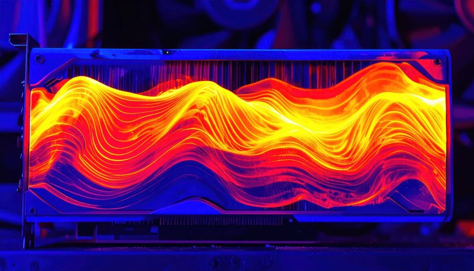
Designers also need to consider Joule heating alongside convective cooling in thermal design. As supply voltages fall and currents rise, copper conductors experience greater self-heating, which in turn changes their electrical resistance. This creates a dilemma in which thermal calculations need current data from power integrity analysis, and power integrity analysis needs temperature data from thermal calculations.
With the Simcenter FloEFD for NX tool, Siemens resolves this dilemma. The tool combines computational fluid dynamics (CFD) and thermal simulation within the NX design environment, allowing designers to see the thermal consequences of their designs before finalizing any geometry. Early thermal simulation helps ensure reliability and compliance, reducing the risk of late-stage redesigns.
Takeaway 4: Teamcenter Ties the Design Chain Together
Teams in mechanical, electronic, simulation, and manufacturing produce their own datasets. Without connections between those datasets, teams must deal with fragmented records that become less reliable later in product development. Siemens provides a solution to this problem with Teamcenter, a product lifecycle management (PLM) platform that ties the digital thread together through all four domains.
Teamcenter provides a multi-domain engineering bill of materials (BOM) that integrates software, electrical, electronic, and mechanical data on a single platform. Its automated alignment between the design and the BOM gives teams an accurate, real-time digital mock-up of buildable product configurations.
Teams can also rely on Teamcenter's change, configuration, and release management to automatically propagate modifications from one domain to the other. For simulation work specifically, analysts can use Teamcenter to find the correct model version associated with the correct design revision, reducing the risk of running analysis on outdated geometry. This ensures data integrity and speeds up cross-domain collaboration.
 Engineering team strategy meeting. Source: AdobeStockDesigning as One Team
As electronics products grow more capable and more compact, the boundaries between mechanical, electronic, thermal, and software teams become harder to manage through manual data exchange. Siemens designed the Xcelerator portfolio to close those gaps through a connected digital thread, giving multi-discipline teams the coordination to move faster and catch failures earlier.
Engineers who want to go deeper into any of the four domains can access the full webinar on demand.
For more information on Siemens’ full suite of electronics design, simulation, and lifecycle management solutions, visit Siemens Digital Industries Software.
Ready to transform your electronics design process?
Explore Siemens Xcelerator or watch the webinar to get started.