Wearable Soft Sensing Suit
A soft sensing suit for monitoring hip, knee, and ankle sagittal plane joint angles. The technology consists of a thin sheet of silicone (a poorly conductive material) sandwiched between two layers of silver-plated, conductive fabric (a highly conductive material), forming a capacitive sensor. This type of sensor registers movement by measuring the change in capacitance, or the ability to hold electrical charge, of the electrical field between the two electrodes.
Technical Specifications
Overview
The technology consists of a thin sheet of silicone (a poorly conductive material) sandwiched between two layers of silver-plated, conductive fabric (a highly conductive material), forming a capacitive sensor. This type of sensor registers movement by measuring the change in capacitance, or the ability to hold electrical charge, of the electrical field between the two electrodes.
System Description
The wearable soft sensing suit encompasses three components: (1) running tights and shoe insoles which serve as the garment base; (2) custom electronics which collect, amplify, and transmit sensor signals; and (3) the six soft strain sensors created from liquid metal embedded in an elastomer. The strain sensors were arranged as follows to measure sagittal plane joint angles:
- two strain sensors to measure hip angles, one placed dorsally on each gluteus;
- two strain sensors to measure knee angle, one placed frontally on each thigh with inextensible webbing routed across the knee to the shin;
- two strain sensors to measure ankle angle, one placed dorsally on each calf with inextensible webbing routed across the heel to a shoe insole beneath the foot.
Garment Base
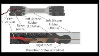
Generic running tights were modified with hook-and-loop fasteners which served as anchor points for the strain sensors. Shoe insoles were also modified with the addition of webbing and hook-and-loop attachment points. The pair of elastic running tights were chosen as the garment base layer and the sensor attachment was designed so it could easily be worn under a layer of clothing if required. Hook-and-loop (Loop 3008 type, Velcro USA Inc., Manchester, NH, USA) was cut into patches and sewn to appropriate positions. Sensors were attached to flexible nylon straps, to avoid being placed on the bony landmarks since the soft sensors were sensitive to surface pressure. The nylon’s much higher elastic modulus (e.g. 4 GPa) than that of our sensor material (30 kPa for Ecoflex 0030) guaranteed transmission of nearly all of the strain of the joint directly to the sensor.
Figure 3: (A) A photograph of an ankle sensor, with its 3D printed mold, flexible circuit, liquid metal, and hook-and-loop fastener components highlighted. (B) A rendered schematic of an ankle sensor with cross-sectional views revealing the channel geometry (150 mm 3 300 mm) and the discretized stiffness gradient of the four included material types (with their Young’s modulus values in parentheses).
Electronics
The custom electronics consisted of a shield board with amplifier circuits for each of the six sensors, a Bluetooth module, and a microcontroller (Figure 2). The soft sensors’ behavior under strain was that of variable resistors. The nominal sensor resistance was near 2.5 O and increased up to 15 O when stretched by 200%. The amplifier circuit operated at the microcontroller’s native reference voltage of 5 V. The circuit applied a precise 502.0 mA DC current through the sensor and then amplified the voltage drop across the sensor resistance through an operational amplifier, which resulted in a linear output voltage to input resistance relationship.
Once amplified, the sensor signal was passed to an Arduino microcontroller (Arduino Mega 2560, Italy) through the on-board analog to digital converter (ADC). A Bluetooth wireless modem (BlueSMiRF Gold, Sparkfun Electronics, USA) transmitted the collected sensor signals to a laptop at up to 135 Hz. Custom MATLAB code on the laptop read the serially transmitted data to produce an animated visual representation of the human (15 Hz refresh rate) while recording the data to file at the maximum 135 Hz for post-processing and characterization. An additional direct wire connection between the microcontroller and optical motion capture system was used to synchronize the start and stop of data collection.
References
Provides detailed description of the project; its goal, requirements, and design approach. Furthermore, detailed description of design & features, and specifications.
Recommended Specs

Continue Reading

How Trixter Used Xsens MVN Animate For The Kangaroo Chronicles

5 minutes read


Xsens Launched MotionCloud At All Digital CES 2021
3 minutes read


with Xsens MVN Analyze
7 minutes read