What is GD&T : Basics and Definitions
This blog post aims to guide you through the basic concepts and definitions of geometric dimensioning and tolerancing (GD&T); more precisely, this includes what GD&T is, how it works, and why it is important to implement GD&T processes. Furthermore, it emphasizes that all of the geometric characteristics and tolerances written on a technical drawing are there for a specific purpose of functionality.
09 Dec, 2022. 8 minutes read
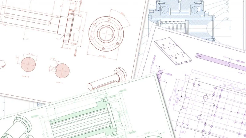
Through its dimensioning and tolerancing information, the technical drawing speaks a language that is intended to be common to all. It is made of a set of very precise standards, symbols, and rules that convey the geometric characteristics and tolerances of a part.
Engineering uses technical drawings in designing and developing products. They are also helpful for choosing the appropriate materials and manufacturing processes during production planning. Part manufacturing and inspection also require the rigorous interpretation of the information communicated by this language. We only have to imagine the magnitude of the technical issues and defaults that would occur if this language did not exist!
What does GD&T stand for: Geometric Dimensioning and Tolerancing.
This blog post aims to guide you through the basic concepts and definitions of geometric dimensioning and tolerancing (GD&T); more precisely, this includes what GD&T is, how it works, and why it is important to implement GD&T processes. Furthermore, it emphasizes that all of the geometric characteristics and tolerances written on a technical drawing are there for a specific purpose of functionality. Sometimes, it tells us that we can be more permissive to reduce production costs. Often, it informs us of the fixing assembly to be used during manufacturing or inspection. Consequently, GD&T must be carefully understood because it imposes a set of constraints that are paramount throughout the entire manufacturing process.
What is GD&T?
GD&T is a system for defining and communicating engineering dimensions and tolerances. It uses a symbolic language in its technical drawings and computer-generated, three-dimensional solid models that explicitly describe the nominal (theoretically perfect) geometry of parts and assemblies. It specifies what degree of accuracy and precision is needed for each controlled feature of the part. It defines the possible size of individual features and the allowable variation in orientation and location between these features.
As a documented design approach and manufacturing mechanism, GD&T helps designers, engineers, and technicians communicate unambiguously with each other; in that way, they can bring a part to life and build it in a way that flawlessly matches its computer-aided design (CAD).
How does GD&T work?
GD&T ensures that everyone involved in technical drawings – from design to machining – speaks the same language. Their vocabulary consists of geometric characteristics, such as flatness, straightness, cylindricity, roundness, perpendicularity, parallelism, angularity, position, profile, concentricity, and symmetry (among others). These different geometric characteristics are sorted into different tolerance categories (e.g., form, orientation, location, and runout) and use datums (e.g., point, line, plane, and volume) as a reference to which other elements in the composition of the part can be related.
A lot of money can be wasted due to misunderstandings between those in research and development (R&D), who design the part, and those who read and interpret the technical drawing at the machine shop. Consequently, the uniform and logical language that is GD&T helps to understand the part’s geometric characteristics and tolerances. Offering uniformity and convenience, it reduces guesswork and interpretation while ensuring consistent geometries across design and manufacturing.
As today’s designs are becoming more and more complex and sophisticated, designers, engineers, and technicians need to rely on the most accurate and reliable communication. GD&T allows everyone on the team to communicate clearly and effectively with one other, saving time and making the design and manufacturing processes even more efficient.
Why implement GD&T processes?
As a universal language that allows engineers and machinists to speak the same vocabulary and understand each other, GD&T is the key to a thorough interpretation of technical drawings. Since some materials are easier to machine than others, the choice of a specific material can be scrutinized for its potential repercussions, which will help reduce the manufacturing costs. After analyzing the technical drawing, one material can then be preferred over another, especially if it has no functional impact on the part.
Another important point that justifies implementing GD&T processes is that each geometric feature has a tolerance, which is the difference between the maximum and minimum limits within which a dimension may vary. Tolerances are used on technical drawings to control parts that must fit together into an assembly. Using tolerances allows for the interchange of parts and the replacement of individual components.
Since the maximum variation between two features is equal to the sum of the tolerances placed on the controlling dimensions, the tolerances of different features accumulate. So, as the number of controlling dimensions increases, the tolerance accumulation also increases. In the worst-case scenario, a machined part could easily be within these accumulated tolerances, but, once at the assembly stage, it might not fit together with the other parts.
With a GD&T approach that controls positions and orientations, however, this aspect of error accumulation is less likely to cause assembly problems. On the contrary, it considers the complete set of tolerances so the model’s manufacturing is repeatable, with parts that are replaceable. By explicitly stating all design requirements, a thorough GD&T process guarantees the accurate fulfillment of all dimensional and tolerance specifications.
Why is GD&T so important?
The more complex a design and the tighter the tolerances, the more sophisticated the tooling that will be required, the more expensive the manufacturing and inspection processes will be, and the higher the scrap rates will pile up. It is, therefore, important to have this in mind when designing a part.
So, instead of putting very tight dimensional tolerancing on positions and hole diameters, which will yield machining to be more expensive and complex, designers and engineers can instead control the profiles and positioning in order to widen the tolerances. This will save them money by reducing the complexity of the manufacturing process.
In this regard, GD&T enhances design accuracy by allowing the appropriate tolerances for maximizing production. The good thing is that, for many projects, the process will provide extra or bonus tolerances to further increase cost-effectiveness.
GD&T and 3D Measurement
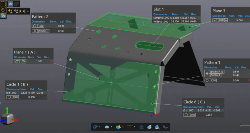
GD&T intertwines with the inspection process. One of the essential phases of quality control and quality assurance is data acquisition, which can be obtained with manual measurement, touch probing, or 3D scanning. Using these techniques, we take a physical part and digitize it. Then, we determine whether the measured values correspond to the expected geometric entities, also known as the GD&T callouts. We see if it passes or fails by comparing the measured data to the dimensions shown on the CAD models. More importantly, we can quantify the deviation from the limit tolerances.
In short, 3D measurement is needed to evaluate GD&T callouts. Once data is acquired by probing a sample of points or scanning a surface, we can assess the part quality and, therefore, the manufacturing process according to specific geometric characteristics, such as flatness, straightness, cylindricity, roundness, perpendicularity, etc.
Definitions
Flatness
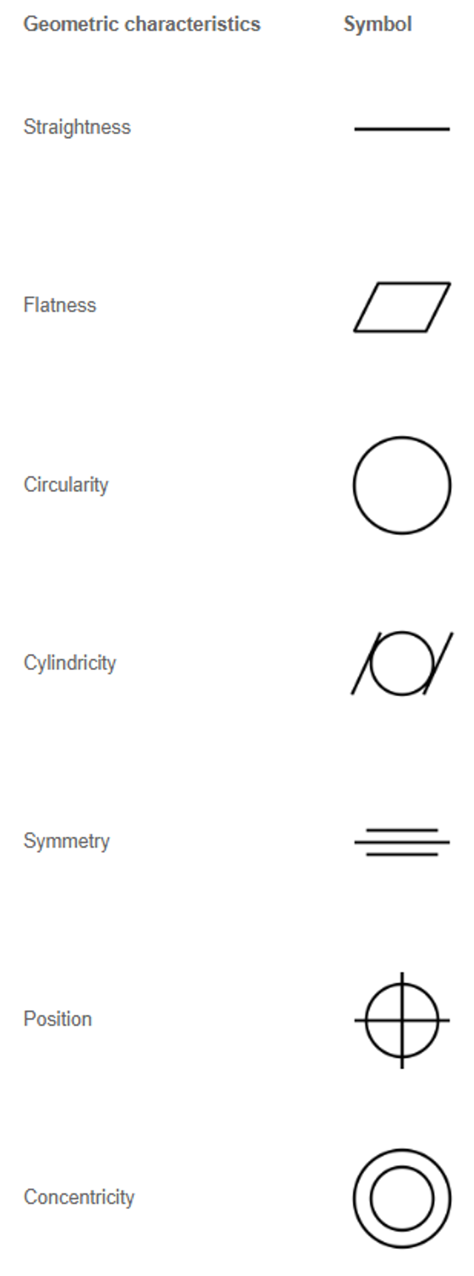
Symbolized by a parallelogram, flatness is the condition of a surface or derived median plane having all elements in one plane. A flatness tolerance specifies a tolerance zone defined by two parallel planes within which the surface or derived median plane must lie.
Straightness
Straightness is a condition where an element of a surface, or derived median line, is a straight line. A straightness tolerance specifies a tolerance zone within which the considered element of a surface or derived median line must lie. A straightness tolerance is applied in the view where the elements to be controlled are represented by a straight line.
Cylindricity
Symbolized with a circle enclosed by parallel lines on each side, cylindricity is a condition of a surface of revolution in which all points of the surface are equidistant from a common axis. A cylindricity tolerance specifies a tolerance zone bounded by two concentric cylinders within which the surface must lie.
Circularity (roundness)
Symbolized by a circle, circularity is a condition of a surface where (a) for a feature other than a sphere, all points of the surface intersected by any plane perpendicular to an axis or spine (curved line) are equidistant from that axis or spine and (b) for a sphere, all points of the surface intersected by any plane passing through a common center are equidistant from that center. A circularity tolerance specifies a tolerance zone bounded by two concentric circles within which each circular element of the surface must lie, and applies independently at any plane.
Perpendicularity
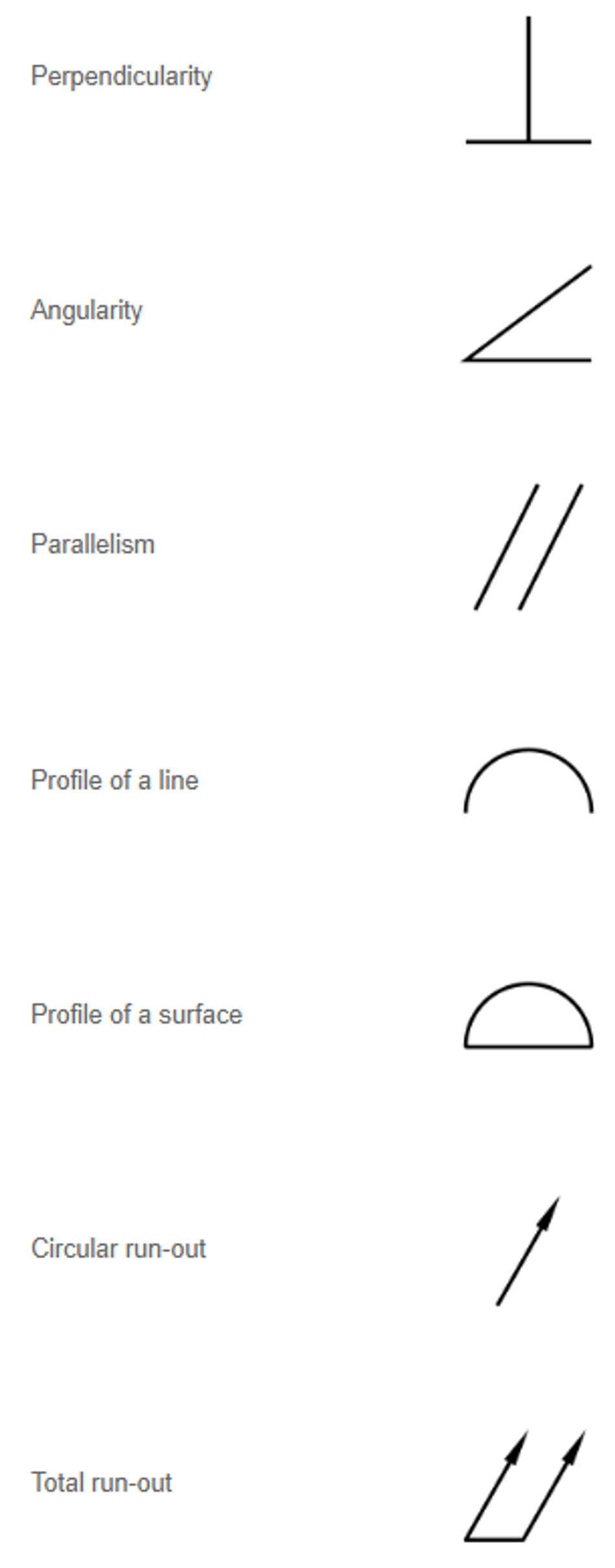
Symbolized by a horizontal line with another line drawn perpendicular to it, perpendicularity is the condition of a surface, feature’s center plane, or feature’s axis at a right angle to a datum plane or datum axis.
Parallelism
Symbolized by two oblique parallel lines, parallelism is the condition of a surface or feature’s center plane, equidistant at all points from a datum plane; or a feature’s axis, equidistant along its length from one or more datum planes or datum axis.
Angularity
Symbolized by two lines at an angle, angularity is the condition of a surface, feature’s center plane, or feature’s axis at any specified angle from a datum plane or datum axis.
Position
Represented by a crosshair symbol, a position is the location of one or more features of size relative to one another or to one or more datums. A positional tolerance defines either of the following: (a) a zone within which the center, axis, or center plane of a feature of size is permitted to vary from a true (theoretically exact) position and (b) (where specified on an MMC or LMC basis) a boundary, defined as the virtual condition, located at the true (theoretically exact) position, that may not be violated by the surface or surfaces of the considered feature of size.
Profile of a surface
Represented by a half-circle with the curved edge facing up and the flat edge on the bottom, the tolerance zone established by the profile of a surface tolerance is 3D (a volume), extending along the length and width (or circumference) of the considered feature or features. Profile of a surface may be applied to parts of any shape, including parts having a constant cross section, parts having a surface of revolution, or parts having a profile tolerance applied all over.
Profile of a line
Each line element tolerance zone established by the profile of a line tolerance requirement is 2D (an area) and the tolerance zone is normal to the true profile of the feature at each line element. A design solid model or a drawing view is created to show the true profile. Profile of a line may be applied to parts having a varying cross section, such as the tapered wing of an aircraft, or a constant cross section, such as an extrusion, where it is not desired to have a tolerance zone including the entire surface of the feature as a single entity.
Concentricity
Concentricity is that condition where the median points of all diametrically opposed elements of a surface of revolution (or the median points of correspondingly located elements of two or more radially disposed features) are congruent with a datum axis (or center point). A concentricity tolerance is a cylindrical (or spherical) tolerance zone whose axis (or center point) coincides with the axis (or center point) of the datum feature(s). The median points of all correspondingly located elements of the feature(s) being controlled, regardless of feature size, must lie within the cylindrical (or spherical) tolerance zone.
Symmetry
Symmetry is that condition where the median points of all opposed or correspondingly located elements of two or more feature surfaces are congruent with a datum axis or center plane. The explanation given in the previous paragraph applies to the considered feature(s), since symmetry and concentricity controls are the same concepts, except as applied to different part configurations.
Circular runout
A circular runout provides control of circular elements of a surface. The tolerance is applied independently at each circular measuring position as the part is rotated to the full angular extent of the surface about the simulated datum axis.
Total runout
Total runout provides control of all surface elements. The tolerance is applied simultaneously to all circular and profile measuring positions as the part is rotated 360° about the datum axis.
Maximum Material Condition (MMC)
Maximum material condition (MMC) is the condition in which a feature of size contains the maximum amount of material within the stated limits of size (e.g., minimum hole diameter, maximum shaft diameter).
Least Material Condition (LMC)
Least material condition (LMC) is the condition in which a feature of size contains the least amount of material within the stated limits of size (e.g., maximum hole diameter, minimum shaft diameter).
Reference: ASME Y14.5-2009, Dimensioning and Tolerancing, Engineering Drawing and Related Documentation Practices, The American Society of Mechanical Engineers (ASME)