Understanding the 3GPP Release 15 5G Standard
This is the fourth article in an eight-part series exploring 5G. The series will explain key terms and technologies and provide an overview of current and future applications for 5G connectivity.
Last updated on 30 Nov, 2020. 10 minutes read

The articles were originally published in an e-magazine, and have been substantially edited by Wevolver to update them and make them available on the Wevolver platform. This series is sponsored by Mouser, an online distributor of electronic components. Through their sponsorship, Mouser Electronics supports a more connected future fuelled by knowledge and innovation.
Introduction
The new Fifth-Generation (5G) standard is a unified mobile communication framework for our connected, mobile society; it supports high data-speed applications as well as mission-critical communications with ultra-reliable and low-latency requirements, and it connects billions of devices that can communicate with each other autonomously. This is the vision the International Telecommunication Union Radiocommunication Sector (ITU-R) laid out in Recommendation M.2083, issued September 2015. Since then, standard-setting organizations have been racing to identify and develop the technology components necessary not only to support urgent short-term market needs, but also to meet the long-term objectives of 5G.
In late 2015, the 3rd Generation Partnership Project (3GPP™) embarked on a mission to define a new Radio Access Network standard—which came to be known as 5G New Radio (NR)—to meet ITU-R requirements. The standardization effort involved channel modeling of spectrum up to 100 gigahertz (GHz), with its vast potential for larger bandwidth allocation, higher throughput, and lower latencies. It also involved studying the scenarios and requirements for next-generation radio access technologies and the corresponding technology components. 3GPP follows a phased approach to standardization, with each phase referred to as a release. The first phase of 5G NR, which supports enhanced mobile broadband and basic ultra-reliable low-latency communications (URLLC) in spectrum up to 52.6GHz, is known as Release 15. The first version of the Release 15 specification became available in December 2017.
Just Completed: Release 16
3GPP has been working at full speed toward completion of the second phase of 5G NR, known as Release 16, which occurred in October 2020. The completion of Release 16 occurred in two stages:
Stage 1: Late 2019 for the physical layer aspects
Stage 2: Late 2020 for the higher layer aspects
Release 16 introduces new capabilities to address the needs of vertical markets, thereby improving the operational efficiency of the Radio Access Network and further enhancing capacity and spectrum efficiency.
This article describes the spectra available in 5G NR and the physical layer enabling technologies developed for 5G NR.
5G NR Spectrum
Given the insatiable consumer demand for mobile data and higher throughput rates coupled with the vast amount of spectrum available in the 3 to 100GHz spectrum region, it seemed natural for regulators and standard organizations to consider opening and using spectrum in centimeter wave (cmWave) and millimeter wave (mmWave) regions for mobile communication, as well as to consider developing a framework for spectrum sharing with incumbent technologies.
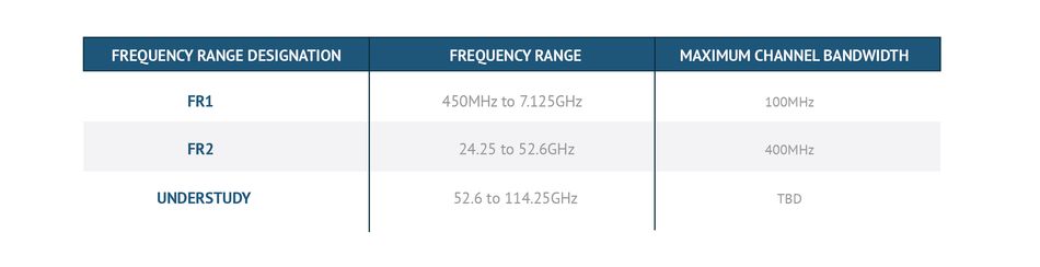
In Release 15, 3GPP has defined two frequency ranges: Frequency range 1 (FR1), which extends from 450 megahertz (MHz) to 7.125GHz, and frequency range 2 (FR2), which extends from 24.25 to 52.6GHz (Table 1). Studies about the availability and regulatory requirements of spectrum in the 52.6 to 114.25GHz frequency range are ongoing, as are the potential use cases and deployment scenarios.
mmWaves
Moving to mmWaves poses challenges in terms of the characteristics of the radio channel and the fact that small-wavelength waves experience a higher rate of attenuation, e.g., due to atmospheric conditions. However, by exploiting shorter wavelengths with smaller antenna array elements that can be packed together more tightly, it’s feasible to implement antenna arrays with tens or even hundreds of antenna elements in the mmWave band. This approach creates antenna systems with high antenna gains and narrow beams that not only compensate for the higher losses experienced by mmWaves but may reduce interference through their narrow beams.
Throughput Optimization
To achieve higher throughput, NR exploits the following techniques:
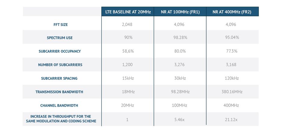
- Higher spectrum utilization. The spectrum use defines the ratio of the transmission bandwidth to the channel bandwidth with guard bands on the edges. In Long-Term Evolution (LTE) communication, spectrum use is 90 percent; in NR, spectrum use can reach 98 percent.
- Higher post–fast Fourier transform (FFT) subcarrier occupancy. In LTE, the number of occupied subcarriers after FFT is about 60 percent of the FFT size. For example, a 20MHz LTE system uses a 2,048-point FFT, of which 1,200 subcarriers are occupied. In NR, the number of occupied subcarriers increases by 25 percent in addition to the increase resulting from higher spectrum use. The channel bandwidth then increases by 25 percent for the same FFT size and subcarrier spacing.
- Larger FFT size. Advances in integrated circuit (IC) technologies make it feasible to support larger FFT sizes. NR supports a maximum FFT size of 4,096, which is double that of LTE.
- Higher subcarrier spacing. In LTE, there is single subcarrier spacing for data transmissions of 15 kilohertz (kHz). In NR, the maximum subcarrier spacing is 120kHz, which increases the channel bandwidth by a factor of eight without the need to increase the number of subcarriers. In FR1, the allowed subcarrier spacings for data transmissions are 15, 30, and 60kHz; in FR2, the allowed subcarrier spacings for data transmissions are 60 and 120kHz.
Table 2 provides two examples for FR1 and FR2 and shows how the preceding techniques increase the throughput.
5G NR Physical Layer Aspects
5G NR is an orthogonal frequency-division multiplexing (OFDM)–based air interface, where the channels and signals in transmission are allocated to individual subcarriers that make up the composite radio signal. OFDM access is the multiple-access scheme that NR has adopted. For downlink and uplink transmissions, without multiuser multiple input, multiple output (MIMO), different users are allocated to different subcarriers.
The waveform of the transmitted signal in NR uses cyclic prefix (CP)-OFDM for downlink and uplink transmissions. In addition, a discrete Fourier transform-spread OFDM (DFT-S-OFDM) waveform is used in the uplink because of the DFT-S-OFDM waveform’s low peak-to-average power ratio (PAPR) for user equipment (UE) in power-limited regions. DFT-S-OFDM is used only with single-layer uplink transmissions. In the case of DFT-S-OFDM, a signal goes through a DFT precoder before reaching the subcarriers allocated for the transmission. After conversion back to the time domain, a CP appends to the OFDM symbol.
Subcarrier Spacing
5G NR is a unified air interface that supports many frequencies, ranging from less than 1GHz to tens of gigahertz—about two orders of magnitude of change in the carrier frequency. Typically, the bandwidth scales with the carrier frequency to maintain a bandwidth-to-carrier frequency ratio within a certain range. Relying only on the number of subcarriers that support different channel bandwidths leads to a small number of subcarriers for small channel bandwidths, which has less multiplexing granularity. Such is the case when relying on a large number of subcarriers for large channel bandwidths, which increases hardware complexity, because it requires FFT/inverse FFT (IFFT) blocks with larger sizes. However, by allowing the subcarrier spacing to scale, it is possible to maintain a reasonable range for the subcarriers while still supporting a range of channel bandwidths. The subcarrier spacing is designed to scale in powers of two, where the supported subcarrier spacing is 15, 30, 60, 120, or 240kHz, with 240kHz in use only for synchronization signals and the broadcast channel.
Low-Latency Transmissions
5G NR introduces several technology improvements designed to support low-latency operations:
Higher subcarrier spacing allows for shorter symbol and slot durations, which leads to lower latencies.
Short physical downlink-shared channel and physical uplink-shared channel transmissions support as few as two symbols.
Support of a flexible scheduling and timing framework with different UE processing capabilities empowers a 5G NR network to optimize a downlink and uplink transmission time, which is based on the UE’s processing capabilities and the latency requirements of corresponding traffic.
Support of preconfigured uplink resources (e.g., configured grant) enables the UE to transmit uplink data autonomously.
Channel Coding
5G NR introduced new channel coding schemes for data and control channels with a payload of 12 or more bits:
- For data channels, 5G NR supports Low-Density Parity-Check (LDPC) codes.
- For control channels with a payload of 12-bits or more, 5G NR supports Polar codes.
- For control channels with a payload of 3- to 11-bits, 5G NR supports Reed-Muller codes.
- For control channels with 1- or 2-bits, 5G NR supports Repetition or Simplex codes respectively
Massive MIMO in 5G NR
5G NR uses massive MIMO, the latest extension of the MIMO techniques, to establish a larger set of antenna arrays with a larger number of elements, thus increasing the efficiency of the 5G network infrastructure. The purpose of massive MIMO is to enhance wireless capacity by improving spectral efficiency through higher order spatial multiplexing and to enhance coverage using beamforming. 5G NR developed a flexible and scalable framework for massive MIMO, which supports:
- Carrier frequencies ranging from less than 1GHz to mmWaves
- Different kinds of antenna array architectures (digital, analog, and hybrid)
- Frequency Division Duplex (FDD) and Time Division Duplex (TDD) modes of operation
There are two mechanisms to enhance spatial multiplexing, which 5G NR employs to optimize its MIMO framework:
- The first is to create a framework to support multiple transmission layers through multiple antenna ports for channel transmission.
- The second is to measure the channel to determine its rank, and then precode information and feed it back to the transmitter to optimally precode the transmission layers across the available antenna ports.
Downlink MIMO
In downlink MIMO, for single-user MIMO (SU-MIMO), the framework supports eight layers per UE, with up to four layers per code word. For multiuser MIMO (MU-MIMO), up to 12 orthogonal demodulation reference signal (DM-RS) ports exist across all UEs.
To determine the channel rank and MIMO precoding coefficients in the downlink, the network can use the Channel State Information (CSI) framework or the Sounding Reference Signal (SRS) framework. The CSI framework consists of two parts: CSI acquisition and CSI reporting. CSI acquisition relies on the CSI Reference Signal (CSI-RS) resource setting, which configures the CSI-RS resources. CSI reporting is done through the CSI report setting, which configures the resources on which the CSI reports. The network uses trigger states to configure a link between the CSI resource and CSI report settings. Alternatively, for TDD systems, the network can use the reciprocity of the downlink and uplink channels that transmit in the same frequency band and use the SRS framework. Using the SRS framework, the UE transmits SRSs on multiple antenna ports. The NR Node B (gNB) measures the channel quality and rank according to the uplink channel and uses this information to determine the channel rank and MIMO precoding coefficients in the downlink.
Uplink MIMO
The uplink MIMO can be either codebook-based or non-codebook-based. For the codebook-based uplink MIMO, the base station measures the uplink channel on the antenna ports of the SRS resource and determines the rank and codebook index of the uplink transmission. For the non-codebook-based uplink MIMO, the UE transmits multiple antenna-precoded SRS resources according to the downlink CSI-RS channel measurements. The base station measures the channel on the SRS resources. Uplink precoding of data at the UE follows the precoding of the SRS resources, which the base station indicates.
Beamforming in 5G NR
Beam management defines a set of procedures that enable transmission and reception of beams in a certain direction within a cell, with narrower angular coverage than cell-wide transmission and reception. One key distinguishing feature of NR is its ability to support beam-based operations. Channels and signals that the base station and UE transmit and receive are beamformed to focus the transmitted energy in a certain direction and thus improve antenna gain. This capability is extremely beneficial for mmWaves, which suffer high propagation losses. It’s also a useful capability for sub-6GHz transmissions.
Beam management involves the following elements:
- Beam determination. Multiple beams cover a cell. Each beam is determined by a source RS and its index. These beams help the base station and UE properly set their transmit and receive beams for the subsequent transmission of downlink and uplink channels and signals.
- Beam measurement and beam reporting. The UE measures the signal quality of each beam and reports each measurement to the network. A measurement can be reported explicitly (e.g., as an RS receives power using the CSI framework) or implicitly (e.g., by transmitting on a resource associated with a beam that meets a signal quality criterion). The network uses this information when determining the beams to use and configure when communicating with the UE.
- Beam sweeping and beam refinement. This functionality allows for the refining of beams (i.e., using narrower beams) and the tracking of beams (i.e., as the UE moves around or changes orientation).
- Beam association for downlink and uplink channels and signals. This framework associates the RS of downlink and uplink channels with a beam’s source RS. The association is based on Quasi Co-Location (QCL) and the Spatial Rx parameters (known as QCL Type D).
- Beam failure recovery. This feature allows for a rapid realignment of the base station and UE beams when a beam is lost, such as during a sudden blockage or upon a fast rotation or movement of the UE.
38 Series
3GPP introduced a new series of specifications for NR—the 38 series. Each 3GPP Radio Access Network (RAN) Working Group (WG) handles a different set of these specifications. Release 15 specifications have a version number V(15.x.y), where a larger x and y value indicate a more recent specification. The full list of the 3GPP specifications can be found on the 3GPP website:
For RAN WG1, which deals with Radio Layer 1, the full list of specifications
For RAN WG2, which deals with Radio Layers 2 and 3, the full list of specifications
For RAN WG4, which deals with radio performance aspects, the full list of specifications
This article was originally written by Emad Farag for Mouser and substantially edited by the Wevolver team. It's the fourth article of an eight-part series exploring 5G. Future articles will explore how 5G differs from existing technology and how the potential of hyper-connectivity will be applied in entertainment, smart cities, and industry and how to get there.
Article One gives an overview of 5G.
Article Two introduces key terms and technologies.
Article Three discusses how systems engineers can evaluate the viability of 5G in the existing connectivity ecosystem.
Article Four examines the relevant standards associated with 5G.
Article Five showcases the radical applications 5G will enable.
Article Six looks at the ecosystems of 5G infrastructure.
Article Seven dives into 5G Antenna Designs.
About the sponsor: Mouser Electronics
Mouser Electronics is a worldwide leading authorized distributor of semiconductors and electronic components for over 800 industry-leading manufacturers. They specialize in the rapid introduction of new products and technologies for design engineers and buyers. Their extensive product offering includes semiconductors, interconnects, passives, and electromechanical components.