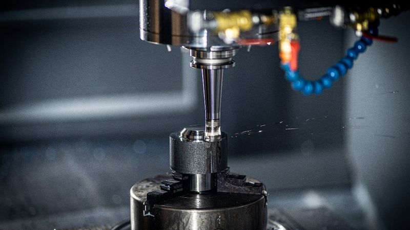
The Guide to Designing Parts for CNC Machining
These 23 tips will help ensure the manufacturability of your CNC machined parts.
CNC machining is a powerful manufacturing technology for creating intricate and accurate parts. However, transforming that initial concept into reality can be a complex journey. The design is the first critical step in ensuring the best possible outcome for your project.
Creating the 3D model of your part using CAD software needs to factor in the capabilities and limitations of the CNC machining process, as well as material properties and tolerances.
To ensure the highest quality of your CNC machined parts, we made this guide to give you tips and best practices to improve your design. These tips can lead to lower costs, an improved manufacturing process, and better parts.
General Design Rules for CNC Machining
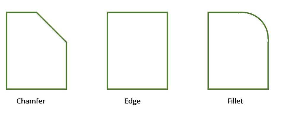
1. Whenever possible, design to lower the cost of labor. Optimizing designs can save time and reduce costs. For example, a chamfered edge –the transitional edge typically at a 45-degree angle – is more manufacturable than a rounded filleted edge.
2. Make things as easy as possible for the manufacturing personnel working on your parts. One way to do that is to avoid generalized statements on drawings. Otherwise, it may be difficult for manufacturing personnel to interpret what you mean. Some of the vague comments we've seen include:
"Polish this surface."
"Corners must be square."
"Tool marks not permitted."
"Assemblies must exhibit good workmanship."
Notes must be more specific than this!
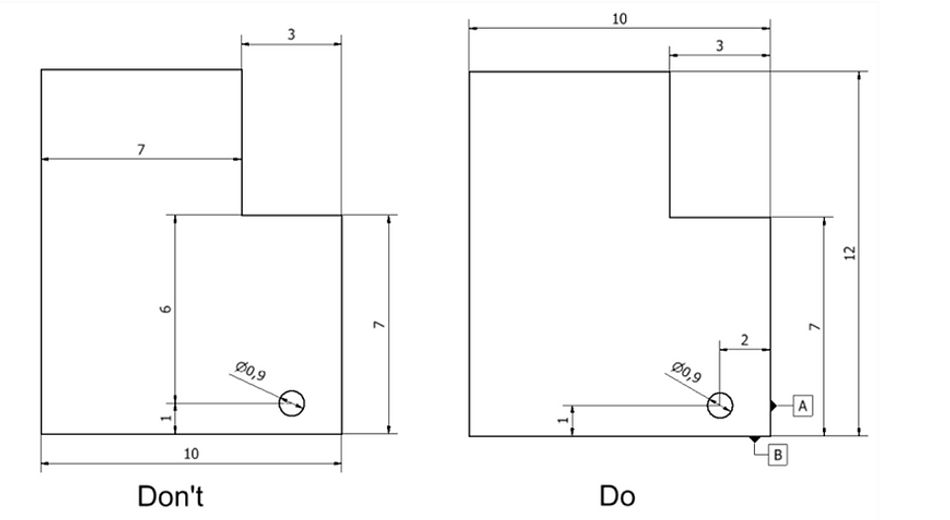
3. Don't show dimensions from points in space in your designs. Instead, show dimensions from specific surfaces or points on the parts. This helps with fixture and gauge making. Importantly, this avoids potential tooling, gauge, and measurement errors.
Furthermore, dimensions should all be from one datum line rather than various points to simplify tooling and gauging and avoid overlap of tolerances.
4. The most important aspect of the design is to fulfill all functional requirements of the part. However, you can focus on making your part lighter once you achieve that.
Why focus on lightness? Fewer materials mean lower costs. Furthermore, lighter parts typically leads lower labor and tooling costs. Designers should always strive for the smallest initial raw material that fulfills strength and stiffness requirements. However, look for the raw materials on online shops to ensure they are available in the size you need.
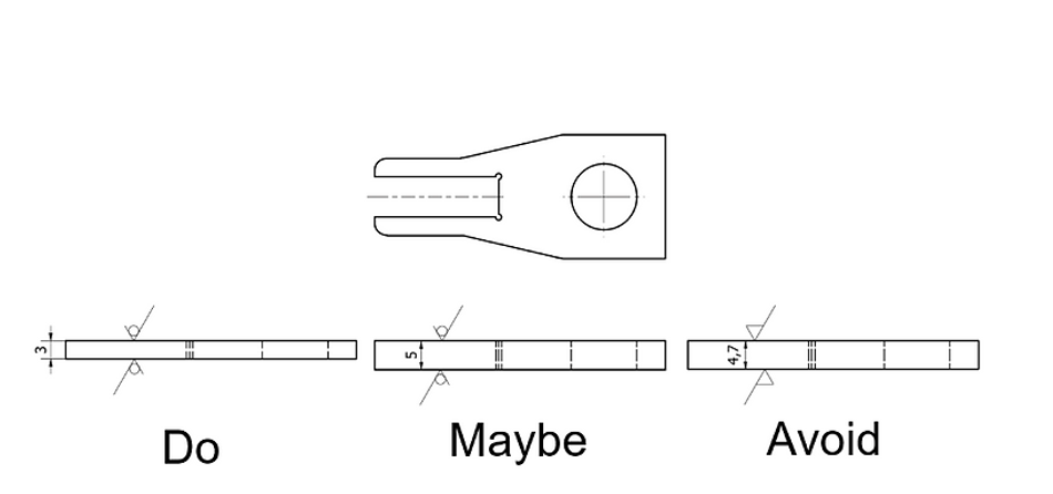
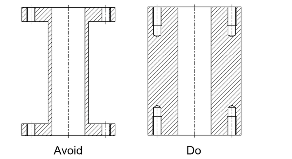
5. Design all the functional geometries on your parts. Add functional geometries to your part, starting from your raw material dimensions and geometry. You should do this because all material extraction results in extra costs. If the part needs to be lighter, use simple geometries like cylinders and blocks and avoid free forms.
6. To further reduce costs, avoid using hardened or difficult-to-machine materials unless their unique functional properties are essential for the part. If you need to search for materials based on mechanical properties like tensile strength, hardness, or chemical composition, use this tool.
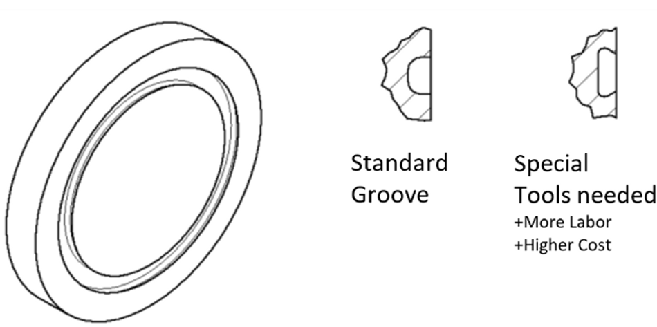
7. The MakerVerse supply chain has an extensive collection of standard, general-purpose, and special toolings. Whenever possible, design with general-purpose toolings in mind to reduce costs. Some of those more expensive special toolings include:
Form cutters
Countersinks other than 90°, 120° and 60°
Unless you're dealing with high-volume productions where scale amortizes the labor and material costs of special tooling, it's best to become familiar with all the general-purpose and standard toolings available. There are many tool catalogs (here's one example - and another) where you can see if the needed geometry is possible.
8. During the design phase, try to make it so that as many manufacturing operations as possible can be performed without needing to reposition the part. Doing this reduces the required handling and ensures accuracy.
9. Use international standards. Define your cutting geometry, norm parts, and processes following international standards (ISO) to ensure they can be understood and produced globally.
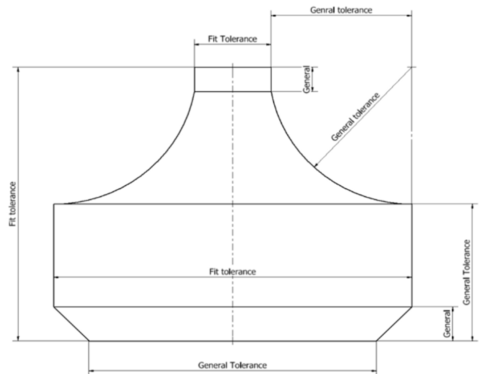
Furthermore, tolerate dimensions so they can be measured with standard measuring tools. Manufacturing precise tolerances requires constant dimensional checking, so design your part to be measured with micrometers, calipers, gauges, and other standard measurement tools.
10. Use stock dimensions and geometries whenever it eliminates a machining operation or the need for an extra surface.
Generally, designers consider the milled part a block where you cut the necessary functional geometries. Turning parts are seen as a cylinder where you remove the required material to create functional features.

11. Avoid interrupted cuts in single-point machining operations, as they shorten tool levels and prevent using faster carbide or ceramic tools.
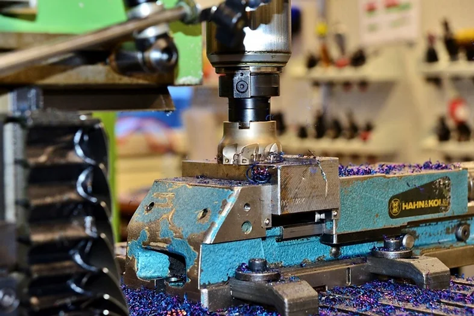
12. Design your part to be rigid enough to withstand the forces of clamping and machining without suffering distortion. The forces exerted by a cutter can be severe. Same with the clamping forces needed to hold the workpiece securely. Parts with thin walls and webs, deep pockets, and deep holes requiring machining can be challenging.
Also, be sure to design the part so that a rigid cutter can be employed while permitting access to the surface.

13. Avoid complex contours as much as possible in favor of rectangular shapes for milled parts and cylindrical shapes for turning parts. Make sure that your parts can be fixed on the most standard fixtures.
14. Design the part for easy fixturing and secure holding during machining operations. To do this, provide a large, solid mounting surface with parallel clamping surfaces to ensure a secure setup with a minimum of 12 mm high for turning machines.
15. Reduce the number and the size of shoulders, as they usually require extra operational steps and material.
16. When designing thin, flat pieces that require surface machining, allow sufficient stock for rough and finished machining. In some cases, stress relieving between rough and finished cuts is also advisable. Rough and finish machining on both sides is sometimes necessary. Allow about 0.4 mm stock for finish machining.
17. To reduce the amount of required operations, it's best to put machined surfaces in the same plane or, if cylindrical, with the same diameter. When surfaces cannot be in the same plane, design them so they can all be machined from one side or the same setup.
18. Provide access room for cutters, bushings, and fixture elements. Design parts so that standard cutters can be used, rather than cutters needing to be ground to a particular form.
19. Avoid projections, shoulders, etc., which interfere with the overrun of a cutter. Instead, provide clearance space at the end of the cut. The space can be cast or formed to minimize machining. This will also provide a noncritical space for burrs.
20. A burr is an unwanted material caused by the CNC machining process. You should expect burrs, provide relief spaces for them, and always design to make it easy to remove them.
21. Shorten the length of your tolerances when possible. All CNC machines have a natural axial deviation defined by the producer. Going beyond that deviations requires extra setup.

22. Avoid thin and long walls, as these tend to deform. If the part is long and thin, you should design with this deformation in mind.
23. Many design for manufacturability (DFM) solutions involve splitting the part. Splitting the part generally leads to less complexity, which can unlock the benefits from many tips in this guide.
Designing for On-Demand Manufacturing
The perfect design is a crucial step in the CNC machining process. The other important step is choosing the right place to turn your design into a finished part. MakerVerse gives you a one-stop shop platform for the full range of advanced manufacturing technologies, including CNC machining and additive manufacturing.
Using the MakerVerse platform, you can leverage the full range of technologies without investing in your own machines.
Simply upload your design, choose your manufacturing technology and material, and receive your quote with the expected lead time. Our engineering and operations experts can personally assist you with your project.
