Smarter Thermal Management for High-Performance Electronics
This whitepaper introduces LTG as a new solution for thermal-aware electronics. It explains how the technology works, what sets its silicon architecture apart from conventional materials, and why it is a phenomenal solution for dense, thermally challenging designs.

03 Sep, 2025. 13 minutes read
In high-performance electronic systems, thermal constraints have arguably become the primary design bottleneck. As power densities rise and product footprints shrink, thermal design becomes essential. Yet, in many workflows, thermal management is still treated as a late-stage add-on to be addressed only after electrical and mechanical design are complete. Such a reactive approach is far from ideal, with the result being bulkier heat sinks, overengineered enclosures, and higher BOM costs. Worse, it can compromise reliability, shorten product lifetimes, and even throttle performance.
Instead, the smarter approach is to consider thermal design from the beginning. Just as current paths and signal integrity are architected early, so too should heat paths be planned and embedded at the system level. That’s the philosophy behind the Lotus Thermal Guide (LTG), a drop-in, silicon-based solution that unblocks direct, low thermal resistance pathways within the PCB or package without disrupting the electrical layout. LTGs allow engineers to offload heat from local hotspots to broader thermal domains or dedicated heat spreaders, with minimal impact on size, cost, or manufacturability.
This whitepaper introduces LTG as a new solution for thermal-aware electronics. It explains how the technology works, what sets its silicon architecture apart from conventional materials, and why it is a phenomenal solution for dense, thermally challenging designs.
Why Thermal Management Matters
Thermal buildup is one of the most limiting factors in modern electronics. While systems continue to deliver higher power in more compact form factors, engineers face tighter thermal margins and increased reliability risks. Without effective thermal planning, components are prone to elevated temperatures that can alter electrical behavior and reduce system performance.
Generally speaking, operating a semiconductor device at elevated temperatures leads to major consequences. Performance is badly affected as the leakage current rises. Switching characteristics drift. Solder joints experience increased mechanical stress. Common failure mechanisms, such as electromigration and dielectric breakdown, become more likely. Over time, the combined effect of these issues shortens the operational lifespan of the system.
Still, despite these risks, thermal management is often addressed too late in the design process. After the board layout is finalized and components are selected, teams may realize the system runs too hot. The response is typically to add bulk in the form of larger heatsinks, thicker copper, or stronger fans. Unfortunately, these late-stage changes increase the bill of materials and frequently fail to eliminate localized hotspots.
A more effective strategy is to address thermal design early. Engineers should plan thermal paths with the same level of intention used for current loops, signal traces, or grounding strategy.
Thermal Management Strategies
Thermal design involves multiple approaches that aim to balance application needs, mechanical constraints, and power density. Common techniques include
Passive cooling, such as heat sinks and thermal spreaders, is mechanically simple but can struggle with dense heat sources or space-constrained layouts.
Active cooling, including fans or liquid systems, improves heat transfer but introduces moving parts, noise, and additional power consumption.
Thermal interface materials (TIMs) that improve thermal contact between components and external heat spreaders but require careful application and degrade over time.
Advanced thermal guides, such as LTGs, create embedded thermal pathways at the component level without disrupting the electrical design or increasing system complexity.
LTG complements conventional solutions by adding direct, low-resistance heat paths that fit where traditional methods cannot. Their ability to conduct heat directly from a component to an internal ground plane or heat spreader gives engineers another degree of freedom in the thermal design process.
What is LTG?
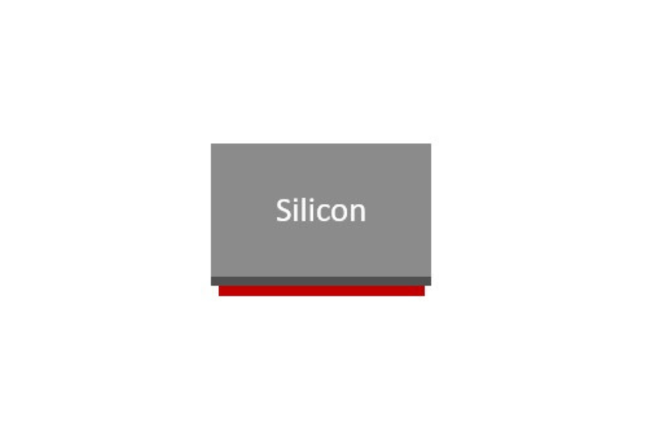
LTGs are thermal components designed to conduct heat from hot, thermally sensitive devices to cooler regions within a system, such as ground planes, copper pours, or heat sinks. They provide a low-thermal resistance, controlled, passive thermal pathway that can be integrated directly into the PCB layout, without affecting signal integrity, consuming power, or impacting board topology.
At the highest level, LTGs function as thermally conductive, electrically isolated bridges between hotspots and thermal domains. Whereas conventional thermal solutions rely on bulk materials or airflow above the board, LTGs operate at the component level. This enables them to dissipate heat in systems with limited space, sealed enclosures, or strict EMI and form factor requirements.
And, unlike conventional heatsinks or fans, LTGs are not constrained by mechanical mounting points or airflow patterns. They can be placed directly beneath or adjacent to components generating the most heat for highly localized thermal relief within dense designs.
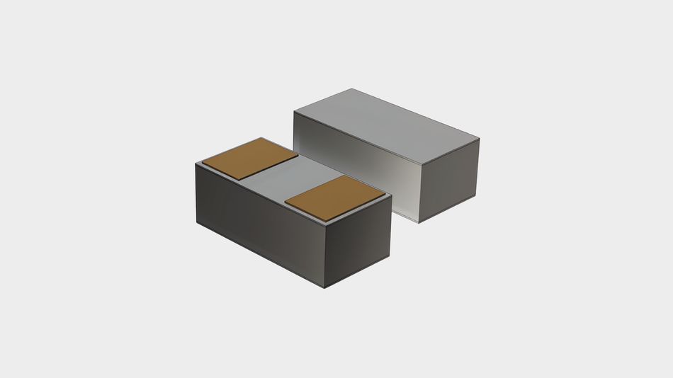
Because LTGs are fabricated from silicon, they offer precise mechanical tolerances, high thermal stability, and full compatibility with standard SMT assembly processes. For example, their surface terminations (SnAg, Cu-Ni-Au, or pure copper) allow reliable solder attachment to standard PCB pads. They are available in standard EIA sizes (such as 0402, 0603, and 0805) and can be further customized in both x-y footprint and thickness to match specific layout constraints or thermal demands.
Why Silicon for LTGs?
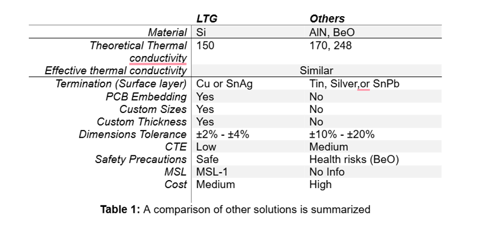
Importantly, LTGs use silicon as their thermal medium rather than ceramic, metal, or polymer.
One advantage of silicon is that, unlike alternatives such as Alumina (Al2O3) or Beryllium Oxide (BeO), silicon is thermally stable across a wide operating range and can be precisely processed using conventional semiconductor tools. As such, silicon enables tight dimensional control, high yield, and cost-effective customization that are difficult to achieve with brittle ceramics or specialty materials.
Another benefit is that silicon’s coefficient of thermal expansion (CTE) closely matches that of other semiconductor and PCB materials, which means it reduces mechanical stress during thermal cycling. This helps maintain solder joint reliability over time in systems subject to frequent power transients or temperature swings.
Finally, safety is an important consideration, as BeO presents a toxic inhalation hazard when fractured or machined. In contrast, silicon is non-toxic and safe to handle throughout assembly and operation.
Lateral LTG Products
Lateral LTGs are designed to conduct heat horizontally across the plane of the PCB. They are mounted between a heat-generating device and a nearby copper pour, ground plane, or embedded thermal zone. This architecture allows for direct thermal routing in the x-y plane and is ideal for systems where vertical space is constrained or where components must remain in close proximity.
Other notable features of lateral LTGs include
Available in standard EIA sizes (0402, 0603, 0805)
Custom sizes and shapes are possible
Solder terminations: SnAg, Cu-Ni-Au, or pure Copper
Performance can be tailored to balance conductivity, leakage, voltage, or capacitance
Vertical LTG Products
Vertical LTGs conduct heat through the z-axis, transferring thermal energy perpendicularly from the PCB plane to a heat spreader, chassis, or other thermally grounded structure. These components are placed between a heat source on the board and a thermal anchor point above or below the PCB for a direct, low-resistance path for vertical heat extraction.
A typical vertical LTG has a fixed height (often around 680 micrometers) with options for customization based on mechanical stack-up or thermal clearance requirements. Like their lateral counterparts, vertical LTGs feature compatible surface terminations that allow solder attachment without adhesives or mechanical clips.
LTG Roadmap
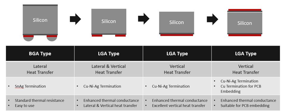
As thermal demands continue to grow across industries, Lotus Microsystems is expanding the LTG portfolio with new formats, enhanced materials, and broader integration options, as shown in Figure 4.
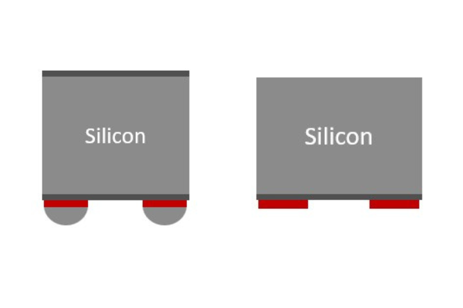
The earliest LTG variants adopt a BGA-type structure with SnAg solder ball terminations. These devices provide lateral heat transfer, are simple to integrate into standard SMT processes, and offer a balanced combination of ease-of-use and standard thermal resistance.
The next evolution introduces LGA-type components with Cu-Ni-Ag plated terminations for both lateral and vertical heat transfer. This configuration increases effective thermal conductivity and allows for more versatile routing across multiple layers of the PCB or toward external heat sinks.
Subsequent versions focus on optimizing vertical conduction. These LGA packages further improve thermal performance in the z-direction and are especially effective for stacked board designs or applications where heat must be extracted through the board to a chassis or housing.
Finally, the most advanced offerings support direct PCB embedding thanks to copper-based terminations and flat, LGA-style geometries. These LTGs provide the highest level of integration and minimize the thermal path between heat sources and internal ground or thermal planes.
Proven LTG Applications
LTGs are useful in any application that generates heat, whether that’s wearable devices or server racks. Some of the industries that are already benefiting from LTGs include
AI and high-performance compute (HPC)
Telecom and networking
Consumer electronics
Within these spaces, some of the most impactful applications that have benefited from the technology include high-power LED systems, optical transceivers (800G+), e-bike motor systems, and drones. The following will explore each application in more detail.
Smarter Thermal Management for High-Power LED Systems
LED applications keep pushing toward higher power densities, and thermal performance has, therefore, become a major design constraint. More drive current produces more light, but it also generates more heat. And, without an effective way to extract that heat, performance suffers. For example, elevated temperatures reduce LED brightness, degrade efficiency, and shorten operating life. To confound matters, conventional thermal solutions, such as bulky heatsinks or aluminum-core boards, are often too large, too costly, or too limited in their ability to handle localized hotspots.

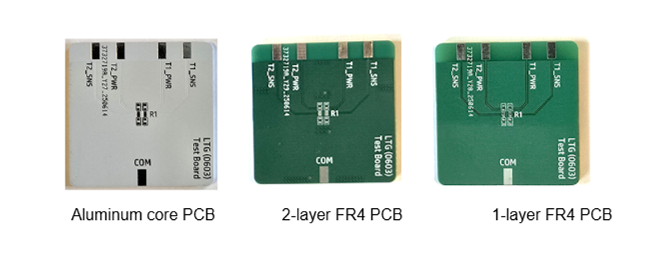
To evaluate LTG’s effect on board-level thermal behavior, Lotus tested a 100 Ω 0603 resistor with 750 mW power loss over 15 minutes under various PCB configurations. Adding just two LTG components produced measurable improvements across each board type
On aluminum-core PCBs, the addition of LTG reduced surface temperature by approximately 8°C
Compared with a single-layer FR4 board, the reduction was approximately 5°C
On a two-layer FR4 board, LTG enabled a 7°C reduction, even outperforming aluminum-core configurations in some cases
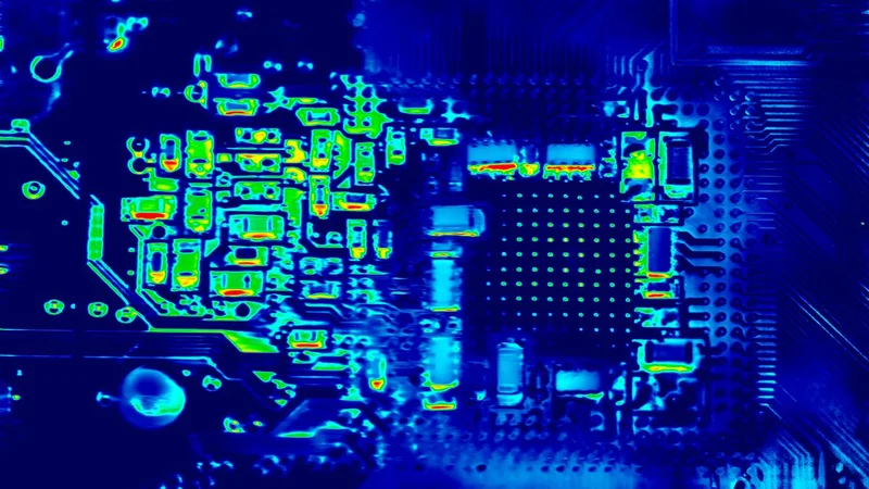
PCB Test Results
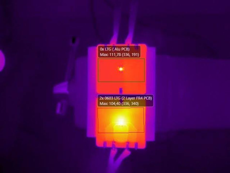
Thermal imagery captured during testing highlights this effect clearly. In Picture 1, the two-layer FR4 board with LTG shows a final temperature of 104.40°C, beating the aluminum-core benchmark despite using a standard FR4 substrate. This shows how LTGs can close the thermal performance gap between high-cost materials and more accessible alternatives.
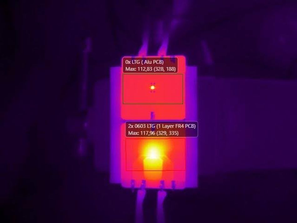
Picture 2 compares the aluminum-core PCB to a 1-layer FR4 board with LTG: while the aluminum board holds at 112.83°C, the FR4 board with LTG reaches 117.96°C. This shows that even with a 1-layer board, LTGs can improve thermal performance to be similar to that of an aluminium board.
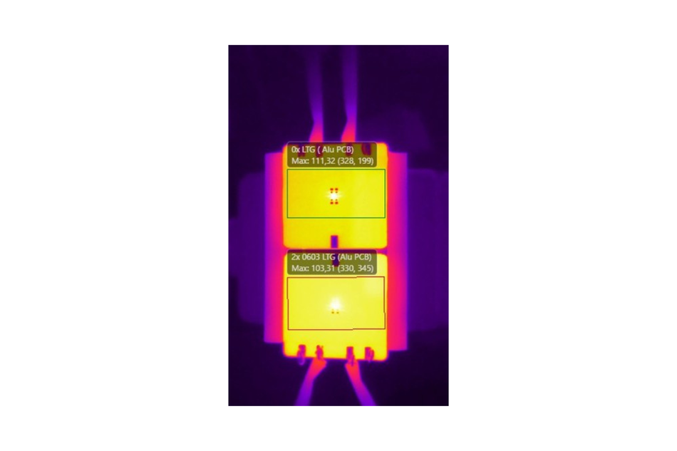
In Picture 3, an aluminum-core PCB with no LTG shows a hotspot at 111.32°C, while the same board with two LTGs drops to 103.31°C.
Collectively, the test results show that LTG enables fine-grained thermal routing that allows designers to extract more performance from standard materials, extend LED longevity, and minimize the need for bulky mechanical elements. By embedding LTGs into the layout from the beginning, engineers gain greater control over thermal gradients in LED systems without increasing board size or assembly complexity.
Flexible Thermal Management Optical Transceivers 800G+
As optical transceivers move beyond 800 G and into 1.6 T territory, thermal management constrains both performance and reliability. At the same time, the growing power density in modern modules challenges conventional cooling methods in the context of extremely compact form factors, where every square millimeter must be optimized.

Several components within these modules contribute significantly to thermal load. Digital signal processors (DSPs) alone can dissipate between 3 and 4 W of power, and that means that, in modules rated above 1 T, total heat dissipation often exceeds 5 W. At the same time, these thermal demands are generally concentrated in physically small areas, resulting in steep local temperature gradients.
Other contributors include silicon photonics (SiPh) modulation drivers and integrated voltage regulators. These components are thermally sensitive and often sit in close proximity to each other, making it difficult to isolate and manage hotspots using traditional approaches. In particular, power ICs and SiPh drivers require careful thermal mitigation to maintain signal fidelity and alignment over time.
Without localized thermal relief, these modules are vulnerable to throttling or premature degradation.
LTG Solves for High-Density Heat with Ultra-Low Cost
LTG offers a compact, passive solution to this problem by unlocking efficient heat redistribution inside the module at the component level.
First, LTG helps mitigate local hotspots by conducting heat laterally away from high-power devices and, thereby, reducing thermal gradients between these sources and the surrounding PCB environment. For components like EML and SiPh blocks, this added stability prevents performance drift and reduces the risk of optical misalignment. A corollary is that, by lowering sustained junction temperatures, LTG contributes to higher mean time between failures (MTBF) and improved long-term reliability.
And, because LTG is a planar SMT component, it boosts reliability without increasing system height. In form factors such as OSFP and QSFP-DD800, every fraction of a millimeter counts. LTG’s zero-profile implementation fits within existing mechanical envelopes and is therefore effective for modules where vertical conduction to a chassis or cage wall is the only available path for heat removal.
LTG also aligns with emerging architectures like linear drive optics and co-packaged optics (CPO), where retimers are removed, and temperature-sensitive analog signals must travel longer distances without degradation. LTG helps preserve signal quality by keeping thermal conditions more uniform across critical paths.
Finally, the use of LTG introduces a greater thermal margin at the system level. By enabling more efficient heat spreading within the module, designers can operate transceivers reliably even at higher inlet temperatures. Where next-generation platforms are pushing 30W per module, increased thermal margin gives switch and router manufacturers much-needed flexibility in thermal budget allocation.
Where to Place LTG for Optical Transceiver
Strategic placement of LTG components is a requisite for achieving optimal thermal performance within 800G+ transceivers. Because these modules operate under strict space constraints and contain densely packed heat sources, LTGs must be positioned as close as possible to thermal hotspots while preserving signal integrity and layout compatibility.
The most effective locations include:
Between heat-generating ICs and ground planes, where LTGs can conduct heat laterally through the PCB stackup and into copper pours
Between PCB layers and heatsinks or cages, where vertical LTGs bridge the gap to the module housing, heat transfer can be directed into the metal enclosure
Underneath DSPs, modulator drivers, and PMICs, where LTGs can offload core heat into surrounding copper areas or heat spreaders
Near analog-sensitive blocks, such as TIA and Rx chains, to stabilize local thermal zones and reduce cross-component temperature variation.
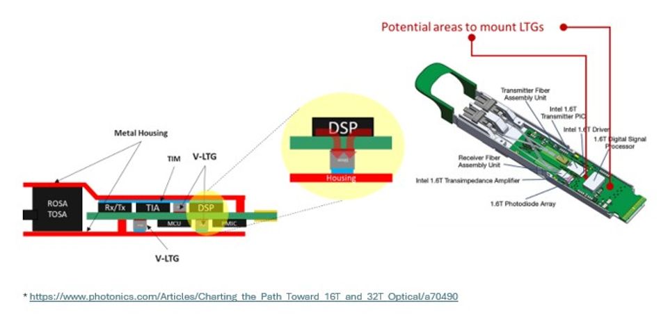
As shown in Figure 5, LTGs can be embedded beneath the DSP or placed along the module edge to transfer heat into the metal housing.
Placement guidelines can also vary slightly by component power level and module construction. For example:
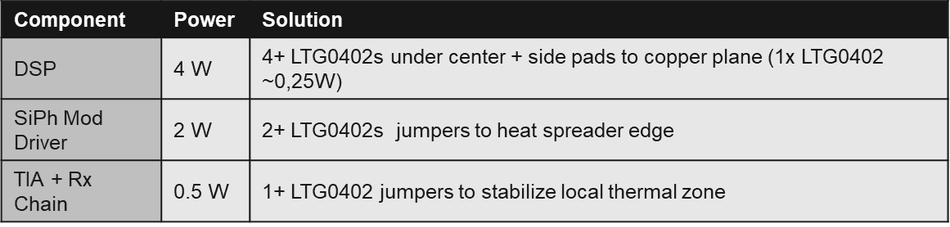
A 4 W DSP may require four or more LTG0402 units arranged beneath the package and along adjacent pads
A 2 W SiPh driver typically uses two LTGs to bridge the device to the nearest heat spreader
A 0.5 W TIA benefits from at least one LTG to prevent thermal buildup in localized zones
By embedding these passive guides early in the layout process, engineers can distribute heat more evenly and reduce the thermal load on any single area of the board without increasing component count or system height.
E-Bike Motor Systems Need Better Thermal Design
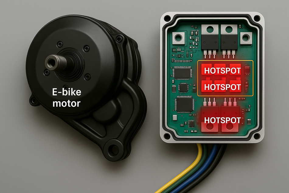
Thermal management in modern e-bike motor systems presents a distinct set of challenges. These motor controllers are typically compact, densely populated, and sealed to meet IP ratings for water and dust resistance. They are often built on FR4 PCBs with limited copper and no forced airflow, yet they are expected to regulate multi-phase motor currents with precision and reliability.

The thermal density of these systems stems from high-current MOSFETs, gate drivers, and current-sensing ICs placed in close proximity. During sustained climbs or hot weather, these components must dissipate significant power within a confined footprint. Traditional thermal solutions, such as external heat sinks or thermal interface materials, are often impractical due to space, weight, or environmental sealing constraints.
LTG offers a path forward by enabling internal heat routing without relying on bulky external components. By conducting heat laterally into copper pours or vertically into the chassis, LTGs help maintain safe junction temperatures, even under peak load. As such, higher continuous current operation can be had in the same board area while improving thermal stability.
Lowering junction temperatures also directly extends component life and improves reliability under harsh conditions. In particular, maintaining cooler MOSFETs allows for better switching behavior and reduced on-resistance, which leads to improved system efficiency. In hot or hilly terrain, where temperature rises rapidly and sustained current draw is required, these benefits compound.
Picture 4 shows a typical motor controller board, where LTGs can be deployed beneath high-power components or along ground planes to redistribute heat toward thermal vias or enclosure surfaces. Because LTGs are drop-in SMT components, they can be integrated without increasing the board’s mechanical envelope or altering the enclosure design.
As such, LTG allows e-bike designers to maintain tight packaging and environmental robustness without compromising thermal performance. In both mid-drive and hub-based systems, LTG makes for a smarter, cooler approach to motor control.
Hotspots in Drone Electronics – Why They Matter
Drones require high-performance computing and power regulation in highly constrained spaces. Regardless of drone application, the underlying electronics are expected to balance compute power, sensor integration, and motor control within a lightweight, thermally isolated enclosure. Naturally, such conditions create concentrated hotspots that, if unmanaged, can lead to instability, degraded efficiency, or early component failure.
The most thermally stressed zones in a typical drone control board include
The central MCU or processor, which handles navigation and control logic
PMICs and voltage regulators, which support power-hungry edge compute and RF systems
ESC drivers and MOSFETs, which switch rapidly and handle high current for motor control
High-current motor input pads, where localized resistance generates significant thermal rise
These hotspots are compounded by dense component placement, minimal thermal mass, and limited airflow. In such environments, traditional heat sinks are often unusable due to weight and space constraints.
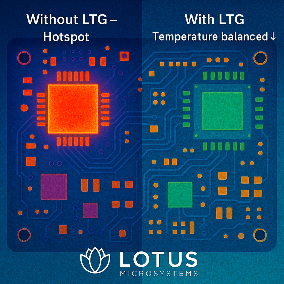
LTG are a powerful solution because it offers passive, board-integrated heat conduction. Placed beneath or adjacent to heat-generating components, LTG units spread thermal energy into copper pours, internal ground planes, or directly to frame-mounted heat spreaders to reduce local temperature peaks without requiring additional board space or active cooling elements.
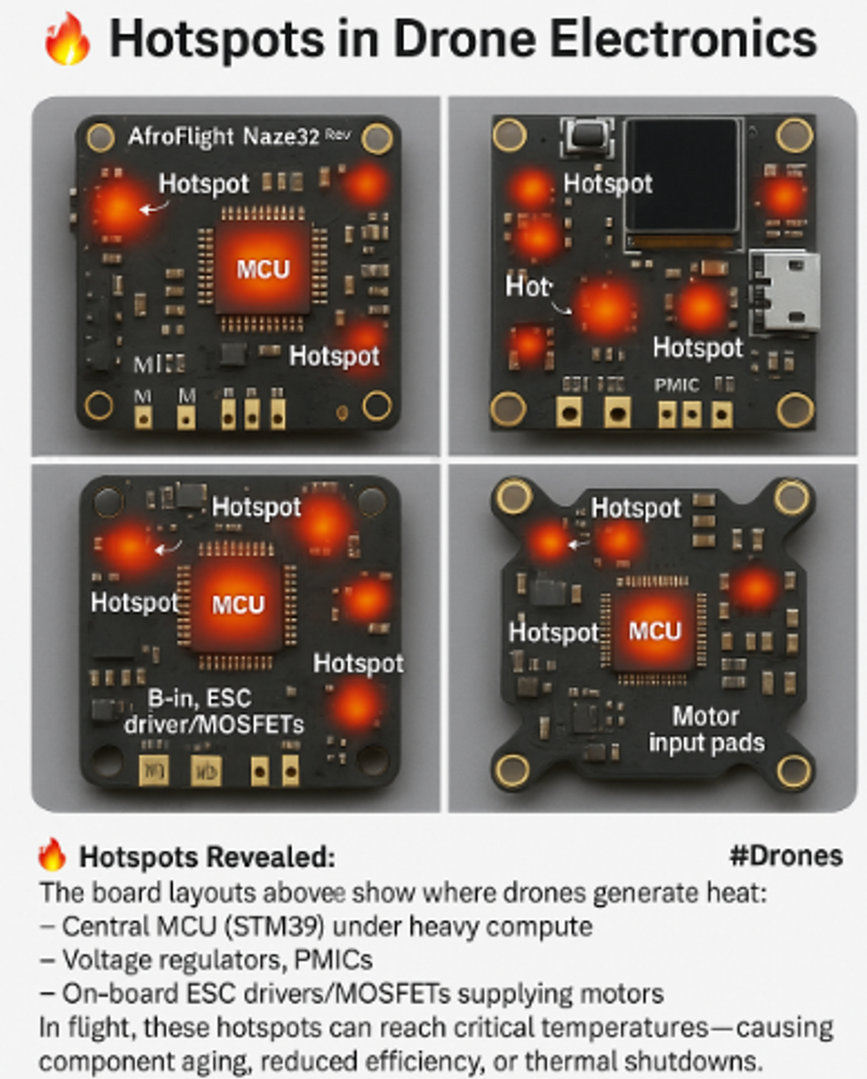
In testing, the use of LTGs has demonstrated up to 40% reduction in hotspot temperature, significantly improved thermal reliability, and even prevented thermal-induced throttling or drift. Picture 5 identifies common thermal stress points across a typical drone controller, while Picture 6 illustrates the effect of LTG in lowering those temperatures under sustained load.
Conclusion
In high-performance electronic systems, thermal constraints must be addressed as early and deliberately as any electrical or mechanical consideration. The closer heat is managed to its source, the more reliably and efficiently the system will perform.
LTGs offer a fundamentally different approach to thermal management. Instead of relying solely on heatsinks, airflow, or exotic board materials, LTGs introduce a board-level solution that fits directly into the layout. By creating embedded, low-resistance pathways from heat sources to cooler regions or chassis interfaces, LTGs help designers manage thermal gradients without altering system architecture or increasing power draw.
Many applications are already using LTGs to realize tangible improvements like cooler junction temperatures, longer component lifespans, higher sustained performance, and lower system cost. By incorporating LTG early in the design process, engineering teams can eliminate late-stage thermal compromises, reduce mechanical overhead, and build systems that are better prepared for the power densities of modern and future applications.