Data Center Cooling Design: Theory, Strategies, and Emerging Technologies
Designing efficient data center cooling systems requires a deep understanding of thermodynamics, energy metrics, airflow management, and emerging liquid cooling technologies. This article explains these concepts and provides practical guidance on implementing sustainable cooling solutions

03 Mar, 2026. 15 minutes read
Key Takeaways
Heat removal fundamentals: Nearly 99% of electrical energy consumed by IT equipment becomes heat; understanding conduction, convection, and radiation is vital to designing effective cooling systems and maximizing overall cooling efficiency.
Optimize air management: Hot‑aisle/cold‑aisle arrangements and containment strategies can cut cooling energy by 10–35 %. Proper sealing, airflow control, and optimized deployment of CRAH units and CRAC units further reduce mixing of hot and cold air.
Monitor and target efficiency metrics: Power Usage Effectiveness (PUE) and Water Usage Effectiveness (WUE) are critical benchmarks. Most facilities operate at PUE 1.5–1.6, but leaders like Google average near 1.10. WUE varies widely—from 0.03 L kWh⁻¹ in EMEA to 0.34 L kWh⁻¹ in the Americas.
Adopt liquid cooling where appropriate: Direct‑to‑chip and immersion cooling support high‑density AI servers, which can save 20–40 % in in high-density deployments. Rear‑door heat exchangers and pumped‑refrigerant economizers provide transitional paths for legacy facilities.
Leverage digital twins and AI: Real‑time sensors, predictive models, and reinforcement‑learning algorithms enable dynamic cooling control. Google’s DeepMind deployment reduced cooling energy by 40 %, and AI‑driven liquid‑cooling models cut operational energy by 9–13 %.
Introduction
Rapid digitalization, cloud adoption, and artificial intelligence workloads are driving explosive growth in data processing. Analysts estimate that global data centers consumed around 1.5 % of the world’s electricity in 2024, with power consumption growing 12 % annually. A projection by Serverion warns that demand could reach nearly 3 % of global electricity by 2030 [1]. Alongside energy, water demand for cooling is surging. Large facilities can consume up to 5 million gallons per day—equivalent to the water use of a town of 10,000–50,000 people [1]. These trends make data center design, especially efficient cooling system design, a critical engineering priority for the coming decade.
Cooling infrastructures, therefore, play a pivotal role in both sustainability and operational resilience. Almost all of the electrical energy supplied to IT equipment becomes heat; if not removed, it raises component temperatures, degrading performance, increasing failure rates, and shortening equipment life. Moreover, inefficient cooling increasesenergy consumption and carbon footprint. The challenge is intensified by high‑density AI and high‑performance computing (HPC) racks that routinely dissipate >30 kW per cabinet and sometimes over 80 kW. Such power densities demand a shift from traditional airflow strategies toward advanced, performance-optimized data center cooling design approaches that integrate both air and liquid technologies.
This article aims to provide engineers with a thorough yet practical guide to data‑center cooling design. We start by revisiting thermodynamic principles and defining key performance metrics. We then examine air‑based and liquid‑based cooling strategies, including economizers, hot‑aisle/cold‑aisle containment, direct‑to‑chip, and immersion cooling. Emerging innovations such as digital twins, reinforcement‑learning controls, and pumped‑refrigerant economizers are discussed. Finally, we outline a design methodology and answer frequently asked questions.
Thermodynamic Fundamentals
Effective cooling design hinges on understanding how heat flows. Heat is a form of energy that moves spontaneously from higher to lower temperature regions. Three mechanisms dominate:
Conduction: Transfer of heat through solid materials. The rate is proportional to the temperature gradient and the material’s thermal conductivity. Metals conduct heat efficiently, while plastics and air insulate.
Convection: Transfer through fluids (liquids and gases). Natural convection relies on density differences (warm air rises; cool air sinks) while forced convection uses fans or pumps to move the fluid.
Radiation: Emission and absorption of electromagnetic waves. Radiative heat transfer becomes significant for hot surfaces but is less dominant at typical server temperatures.
Because cooling involves removing heat rather than adding cold, designers must provide sufficient pathways for heat to exit the IT equipment. A single blade server can dissipate about 4 kW(equivalent to forty 100‑W light bulbs), and rack densities are climbing. The thermal environment must also obey the ideal gas law, linking temperature, pressure, and volume: PV=nRT. This law underpins psychrometric charts used to select supply‑air temperature and humidity.
Recommended Reading: How ChatGPT Is Transforming the Data Center
Heat Load Estimation
Before selecting a cooling system, engineers should estimate the total heat load, which includes:
Load component | Typical contribution | Notes |
IT equipment | ~100 % of its electrical power becomes heat | Servers, storage, networking, GPUs. |
Power infrastructure | 5–15 % | UPS, power distribution, and conversions. |
Lighting and people | 1–2 % | Varies with occupancy. |
Solar gain and building envelope | 1–5 % | Only relevant for above‑ground facilities. |
Designers must also account for future growth, particularly in AI clusters where power densities may double within a few years.
Environmental Requirements and Efficiency Metrics
ASHRAE Temperature and Humidity Guidelines
The American Society of Heating, Refrigerating, and Air‑Conditioning Engineers (ASHRAE), a key authority in HVAC, publishes recommended server inlet temperature and humidity ranges. For the most common Class A1 equipment, ASHRAE recommends an inlet temperature of 18–27 °C (65–80 °F), with many operators targeting 20–24 °C (68–75 °F) for better energy savings [2]. Recommended relative humidity is 40–60 % or a dew‑point temperature between 5.5–15 °C (42–59 °F). Too dry air increases electrostatic discharge risk, while too humid air leads to condensation and corrosion.
Power Usage Effectiveness (PUE)
PUE is a key metric developed by The Green Grid to assess data‑center energy efficiency. It tells you how much of the total facility power goes to IT equipment versus overhead (cooling, lighting, etc.). It is defined as:
` PUE= (Total Facility Power/ IT Equipment Power)
Where:
Total Facility Power = all power entering the data center (kW, MW, or kWh)
IT Equipment Power = power used by servers, storage, and networking (excluding cooling, lighting, etc.)
A perfect PUE of 1.0 means every watt is used directly by IT equipment. In practice, most facilities operate between 1.5 and 1.6, meaning that about 50% of the energy powers cooling and other overhead. However, leading hyperscale operators have achieved much lower PUEs. Google reports a fleet-wide trailing 12-month PUE of 1.09, using continuous measurement across all seasons. Facilities such as the Dublin site and Eemshaven, Netherlands, consistently operate near 1.07–1.08 [3]. These results show that careful design, advanced controls, and free‑cooling strategies can drastically reduce overhead energy.
Water Usage Effectiveness (WUE)
WUE quantifies the water consumed by the cooling system per kilowatt‑hour of IT energy. It is defined as:
WUE=Annual Water Usage (L) / IT Equipment Energy (kWh)
An ideal WUE is zero (no water used), but this is achievable only with completely air‑cooled systems. In practice, global average WUE stands around 1.9 L kWh⁻¹, with large regional differences. Microsoft’s fiscal‑year 2025 data showed a WUE of 0.03 L kWh⁻¹ in EMEA and 0.34 L kWh⁻¹ in the Americas [5]. Operators must balance PUE and WUE: evaporative cooling can reduce PUE but increase water consumption, while dry cooling conserves water but uses more energy.
Environmental Impact of Water Use
Data center water consumption has become a pressing sustainability issue. Medium‑sized facilities may consume 110 million gallons of water per year, while larger centers can draw up to 5 million gallons per day. Collectively, U.S. data centers may use 449 million gallons per day. With only 0.5 % of the Earth’s water accessible and drinkable, and increasing droughts, responsible cooling design must prioritize water efficiency and consider closed‑loop or dry‑cooling solutions.
Air-Based Cooling Systems
Air cooling systems remains the foundation of most legacy and many modern data center facilities. Despite the rise of liquid cooling for high-density AI workloads, CRAC units and CRAH units continue to serve as primary cooling units in enterprise, colocation, and hyperscale environments. Their design, configuration, and control strategies significantly influence overall cooling efficiency, PUE performance, and operational reliability.
CRAC Units (Computer Room Air Conditioners)
CRAC (Computer Room Air Conditioner) units are widely used air-based cooling systems that operate using a direct expansion (DX) refrigeration cycle. In these systems, the refrigerant absorbs heat from return air and rejects it through a condenser, with the compressor integrated inside the unit.
Because CRAC units are self-contained, they are well-suited for small to mid-sized facilities and edge data centers where installing a centralized chilled-water plant may not be practical. They offer relatively fast installation and lower upfront capital costs, making them attractive for legacy and modular deployments. However, since each unit relies on its own compressor, energy consumption increases significantly as facilities scale.
At higher rack densities—typically above 20–30 kW per rack—airflow and compressor limitations reduce cooling efficiency. As a result, while CRAC units remain common in traditional environments, they can become less efficient in large hyperscale data center designs.
CRAH Units (Computer Room Air Handlers)
CRAH (Computer Room Air Handler) units are air-based cooling systems that use chilled water supplied from a centralized chiller plant instead of relying on integrated compressors. In this configuration, warm return air from the data hall passes over a chilled-water coil inside the CRAH unit, where heat is transferred to the water loop and then rejected at the central plant.
This architecture delivers higher cooling efficiency in large-scale data center design because chilled-water plants operate more efficiently at scale compared to multiple distributed DX systems. CRAH units also integrate seamlessly with water-side economizers, enabling free cooling when outdoor wet-bulb conditions are favorable, which significantly improves overall cooling efficiency and reduces operational costs.
Since the compressor equipment is located outside the data hall, mechanical complexity, noise, and maintenance requirements inside the white space are reduced. For these reasons, CRAH-based systems are better suited for hyperscale and high-density deployments and are widely adopted by major data center operators such as Google.
Air Management Strategies
Hot‑aisle and Cold‑aisle Containment
One of the simplest yet most effective air‑management practices is the hot‑aisle/cold‑aisle arrangement. In this layout, server racks are arranged so that the cold air intakes face each other (creating the cold aisle) and the hot exhaust air face each other (creating the hot aisle). Perforated floor tiles deliver cool air into cold aisles, while return air travels through ceiling plenums or return vents. By preventing mixing, this arrangement reduces fan energy and allows higher supply‑air temperatures, yielding 10–35 % cooling energy savings.
Containment systems enhance this concept by physically separating hot and cold airstreams using aisle‑level barriers or rack‑level chimneys. Lawrence Berkeley National Laboratory recommends sealing cable penetrations, rearranging perforated tiles, covering openings, and deploying blanking panels to maintain segregation and minimize bypass air [6].
Raised Floors and Airflow Control
Raised floors allow cold air to be distributed under the racks and delivered through perforated tiles. Proper tile placement is critical: too many open tiles or misaligned ones can cause short‑circuits in air paths. Computational fluid dynamics (CFD) simulations and thermal imaging help optimize tile layout and identify hotspots. Variable‑speed fans in Computer Room Air Handlers (CRAHs) or Computer Room Air Conditioners (CRACs) further tune airflow to match load.
Free Cooling via Economizers
Economizers harness favorable outdoor conditions to provide “free cooling”, reducing reliance on compressors and chillers. They come in three primary forms:
Air‑side economizer: Introduces filtered outdoor air into the data hall and exhausts warm air to the outside. This method is effective in climates where outdoor temperatures stay below 21 °C (70 °F) for much of the year. Technology giants such as Google’s Belgian data center and Microsoft’s Dublin facility have used air‑side economizers to achieve PUEs as low as 1.07. The design must account for humidity and air quality, often mixing return air with outside air to regulate temperature.
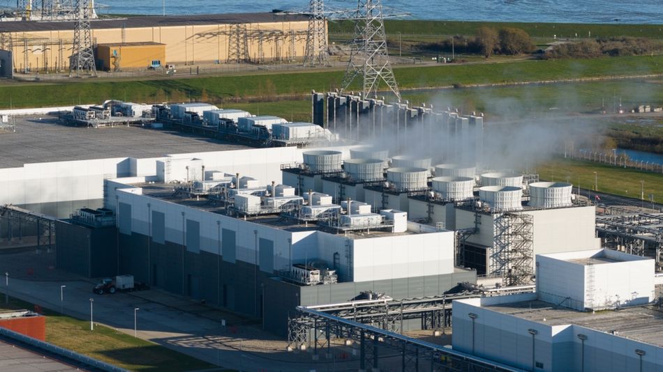
Water‑side economizer: Utilizes cooling towers to cool water without operating the chiller. When outdoor wet‑bulb temperatures are low, warm return water from the data hall is routed through a heat exchanger, and condenser water rejects heat to the atmosphere via an evaporative tower. This approach is ideal when a water‑cooled chiller plant already exists. It eliminates compressor energy during suitable conditions and can deliver full free cooling, though water consumption must be monitored.
Refrigerant‑based economizer: A newer option that uses pumped refrigerant instead of water. Pumps circulate refrigerant from the condenser to the evaporator, enabling heat rejection without compressors. Refrigerant can carry twice as much heat as water and 40 times more than air, achieving PUE values as low as 1.05. These systems can often be located outside the data hall, saving space and expanding climate applicability.
Liquid Cooling Technologies
As rack densities exceed the limits of air cooling, liquid cooling provides a powerful alternative. Liquids have over 1,000 times the volumetric heat capacity of air, enabling direct heat removal from high‑power components.
Direct‑to‑chip (D2C) Cooling
D2C systems transfer heat from hot components directly to a cold plate that contacts the processor or GPU. The heat is carried away via a coolant loop to a heat exchanger or coolant distribution unit (CDU). Key elements include cold plates, pumps and piping, CDUs and coolant, typically deionized water or dielectric fluid. The market for D2C cooling is projected to grow rapidly, from US$ 1.96 billion in 2022 to US$ 5.62 billion by 2030 (CAGR 19.7 %).
Advantages of D2C systems include:
High thermal efficiency and the ability to cool high‑power AI and HPC chips.
20–40 % energy savings relative to air cooling.
Reduced noise and smaller footprint because server fans and CRACs can be downsized or eliminated.
Improved hardware reliability due to lower operating temperatures.
However, designers must consider compatibility, leakage protection, redundancy, coolant maintenance, and integration with DCIM/AI systems. D2C is often deployed in conjunction with air cooling for non‑liquid‑cooled components; thus, hybrid air–liquid systems are common.
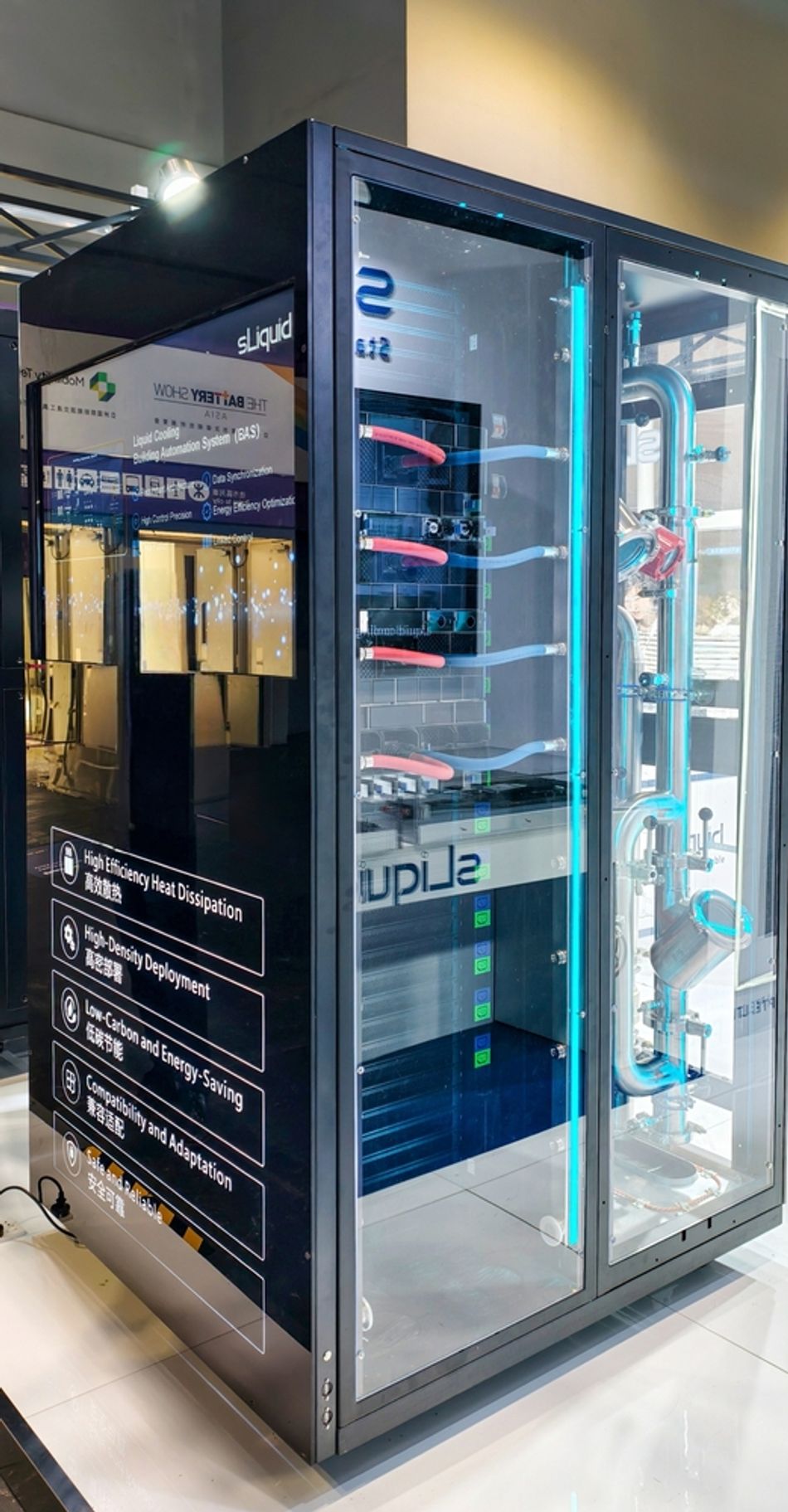
Immersion Cooling
Immersion cooling submerges servers or server modules in a dielectric liquid. Two main variants exist:
Single-phase Systems
Two-phase Systems
Single‑phase systems use a circulating pump to move the liquid over components and through a heat exchanger, while two‑phase systems rely on the liquid boiling off and condensing on a coil. Benefits include very low thermal resistance, elimination of server fans, protection from dust and humidity, and the potential to recover waste heat. Immersion cooling can enable extremely high rack densities and is particularly attractive for AI training clusters.
Nevertheless, adoption faces challenges: hardware compatibility, integration with facility infrastructure, maintenance procedures, and coolant management. The technology also requires a larger upfront investment and specialized enclosures.
Rear‑door Heat Exchangers (RDHx)
RDHx devices mount on the back of a standard rack and contain a liquid‑cooled coil that absorbs exhaust heat before it enters the room. They allow hot air to remain at the server level while chilled water removes the heat. RDHx units can be passive (using server fans only) or active (adding fans in the door). Benefits include:
Retrofitability for existing air‑cooled data halls.
Support for 15–30 kW per rack without major room modifications.
Reduced reliance on room‑level CRACs and potential PUE improvements.
Designers must ensure proper chilled‑water temperatures, manage condensation risk, and plan cabling and piping. RDHx provides a cost‑effective stepping stone toward more advanced liquid cooling.
Digital Twins and AI‑driven Control
Digital Twin Technology
A digital twin is a virtual representation of a physical system that is continuously updated with real‑time data. In data centers, digital twins can simulate airflow, thermal distribution, and energy consumption. The global digital twin market is projected to grow from US$ 24.48 billion to US$ 259.32 billion by 2032 (CAGR 40.1 %). Benefits for cooling design include:

Visualization of airflow and hotspots at rack, row, and room level.
Predictive analysis of what‑if scenarios—such as rearranging racks, changing fan speeds, or raising supply‑air temperature—without disrupting operations.
Integration with sensors and DCIM to continuously update the model and monitor real‑time conditions.
Potential carbon‑emission reductions up to 50 % according to research.
Companies like Schneider Electric and ABB are already deploying digital twins to optimize power distribution and cooling design. For engineers, incorporating digital‑twin analysis early in design enables better sizing of cooling systems, airflow paths, and economizer configurations.
AI‑driven Dynamic Cooling
AI and machine learning bring adaptive intelligence to cooling systems. Sensors collect data on temperatures, airflow, power loads, and environmental conditions; digital twins simulate outcomes; and AI algorithms make optimal control decisions. The Araner report highlights key aspects:
Real‑time monitoring and predictive analytics: Sensors feed digital‑twin models, which forecast thermal behavior and adjust cooling accordingly.
Intelligent cooling algorithms: Reinforcement‑learning models learn control strategies over time, optimizing fan speeds, coolant flow, and chiller operation. Simulations have shown 9–13 % energy savings over conventional control.
Energy efficiency gains: Google’s deployment of DeepMind AI achieved a 40 % reduction in cooling energy.
Reliability and longevity: AI detects anomalies, prevents thermal stress, and schedules predictive maintenance.
Scalability for AI workloads: As data‑center electricity consumption is forecast to triple due to AI adoption, AI‑assisted cooling ensures systems can scale without unsustainable energy increases.
Implementing AI‑driven cooling requires robust instrumentation, high‑resolution data streams, integrated control platforms, and cross‑disciplinary expertise. Engineers must also address cybersecurity, data governance, and explainability when deploying machine‑learning algorithms in mission‑critical facilities.
Recommended Reading: The Future AI-Driven Data Centres: Bridging Performance and Sustainability
Sustainability and Renewable Integration
Balancing PUE and WUE
Optimizing PUE alone is not sufficient; water consumption must be considered. Evaporative cooling and water‑side economizers improve PUE but increase WUE. Conversely, dry cooling and refrigerant‑based economizers conserve water but may raise PUE. The Uptime Institute notes that the global average PUE has remained flat for several years because improvements in new hyperscale facilities are offset by older enterprise sites [4]. Achieving sustainability thus requires a holistic view of energy and water.
Waste‑heat Recovery
Rather than dissipating heat, some data centers recover it for district heating or industrial processes. Serverion highlights how waste‑heat recovery can turn the data center into an energy source, reducing overall emissions. When combined with liquid cooling—especially immersion or direct‑to‑chip—the higher temperature of the coolant makes heat recovery more efficient.
Renewable Energy and Energy Campuses
Integrating renewable energy is essential for reducing indirect water use and carbon emissions. In 2024, wind and solar supplied about 24 % of the electricity used by U.S. data centers. Operators like Cisco and Google deploy on‑site solar farms and wind turbines to power their on-site facilities. The concept of energy campuses, where renewable generation and data‑center infrastructure coexist, allows for off‑grid operation and reduces transmission losses.
Water Stewardship
Facilities built near freshwater bodies sometimes tap into aquifers or rivers for cooling, stressing local resources. Engineers should explore alternatives such as:
Dry or adiabatic coolers: Use ambient air with minimal water spray; may require larger heat exchangers.
Closed‑loop liquid cooling: D2C and immersion systems with liquid‑to‑air or liquid‑to‑liquid heat exchangers can reduce water usage by up to 70 %.Seawater cooling: Where available, seawater can replace freshwater, as practiced in some Nordic data centers.
Sustainability certifications such as LEED, BREEAM, and the European Code of Conduct for Data Centre Energy Efficiency encourage transparent reporting of PUE, WUE, and carbon intensity. Compliance may become mandatory as governments tighten regulations.
Design Methodology and Practical Implementation
Designing a data‑center cooling system involves multiple steps:
Define Requirements and constraints: Determine IT load, future expansion, reliability tier (e.g., Uptime Institute Tier III/IV), site climate, and regulatory requirements.
Select air‑management strategy: Evaluate hot‑aisle/cold‑aisle containment, raised floor vs. slab, and decide whether to implement cold‑aisle or hot‑aisle containment. Perform CFD simulations to optimize tile placement and identify hotspots.
Choose cooling technology: Compare air cooling with liquid cooling options. For moderate densities (< 10 kW per rack) and cost‑sensitive projects, air cooling with economizers may suffice. For high‑density AI racks (> 30 kW), consider D2C or immersion cooling.
Plan economizer integration: Analyze local climate to determine the feasibility of air‑side and water‑side economizers. Use weather data and psychrometric analysis to estimate hours of free cooling per year. For pumped‑refrigerant economizers, evaluate PUE improvements and mechanical considerations.
Incorporate digital twins and monitoring: Build a digital model to simulate airflow and temperature distribution, test design variations, and plan maintenance. Integrate sensors for temperature, humidity, flow, and power. Adopt DCIM platforms to centralize monitoring and control.
Implement redundancy and resiliency: Provide N+1 or 2N redundancy in cooling equipment, pumps, and power supplies. Ensure leak detection and containment for liquid systems. Develop emergency procedures and predictive maintenance schedules using AI analytics.
Commissioning and validation: Perform integrated system testing (IST) to validate the design against load conditions. Adjust control setpoints, calibrate sensors, and verify PUE/WUE measurements. Iterate using digital twins to fine‑tune performance.
Operational optimization: Continuously monitor PUE and WUE, adjust cooling setpoints based on ASHRAE allowable ranges, and deploy AI algorithms to reduce fan speeds and chiller energy. Review performance periodically and plan upgrades as technology evolves.
Practical Considerations for Liquid Cooling
Leak detection and containment: Use dripless quick‑disconnect fittings, pressure sensors, and leak‑containment trays. Provide isolation valves and redundant pump paths.
Coolant selection: For D2C, deionized water offers high thermal conductivity but must be maintained; dielectric fluids reduce electrical risk at the cost of lower heat capacity. Immersion fluids must be inert, thermally stable, and recyclable.
Facility integration: Plan for CDUs, pipes, manifolds, and heat‑rejection equipment. Ensure compatibility with existing chilled‑water plants, and design for easy maintenance access.
Upgrade paths: RDHx units can retrofit existing racks, and pumped‑refrigerant economizers can add free cooling to old facilities. These transitional technologies allow gradual adoption without full replacement.
Future trends and innovations
High-Density Computing and Emerging Cooling Methods
The rise of generative AI and HPC is driving rack densities towards 80 kW and beyond. To meet these demands, researchers and vendors are exploring:
Pumped refrigerant and micro‑channel coolers: Offer extremely high heat‑flux removal with compact footprints.
Hybrid liquid–air systems: Combine D2C for CPUs/GPUs with air cooling for memory and storage, balancing efficiency and cost.
Waste‑heat–to‑power cycles: Use absorption chillers or organic Rankine cycles to convert waste heat into electricity, further improving PUE.
Hydrogen fuel cells and on‑site energy storage: Provide resilient power while producing only water as a by‑product; integrated thermal management recovers waste heat.
Regulatory and Social Drivers
Governments and investors increasingly demand transparent reporting of energy and water use. EU regulations increasingly require transparency and reporting of energy performance metrics such as PUE. Engineers should prepare for climate‑adaptation strategies, such as using reclaimed water, designing for heat‑wave resilience, and participating in district heating networks.
Conclusion
Data‑center cooling design sits at the intersection of thermodynamics, hardware engineering, sustainability, and digital innovation. As this article has shown, effective cooling begins with a solid grasp of heat transfer and environmental requirements. Air‑management practices such as hot‑aisle/cold‑aisle layouts and economizers deliver significant energy savings, while liquid‑cooling technologies address the challenges of high‑density AI workloads. Advanced approaches—digital twins, AI‑driven controls, and pumped‑refrigerant economizers—are pushing efficiency boundaries and enabling real‑time optimization. Meanwhile, sustainability metrics like PUE and WUE remind us that energy and water are finite resources; balancing them requires careful design and continuous monitoring.
For digital design engineers, hardware engineers, and electronics students, the journey toward efficient data‑center cooling is both technical and strategic. By leveraging the concepts and strategies outlined here, you can design systems that not only keep servers cool but also reduce environmental impact, lower operational costs, and ensure resilience in an era of relentless digital growth.
FAQ
1. What is Power Usage Effectiveness (PUE)?
PUE is the ratio of total facility energy to IT equipment energy. A lower PUE indicates that more of the consumed energy goes directly to computing rather than overhead. Most data centers operate between 1.5 and 1.6, while leaders like Google report 1.09.
2. How does Water Usage Effectiveness (WUE) differ from PUE?
WUE measures litres of water consumed per kilowatt‑hour of IT energy. It captures the water footprint of cooling systems. While PUE focuses on energy, WUE addresses water stewardship. Green facilities aim for low values such as 0.03 L kWh⁻¹.
3. Why use hot‑aisle/cold‑aisle layouts?
Arranging racks so that cold intakes face each other and hot exhausts face each other prevents mixing and allows higher supply‑air temperatures. This simple strategy can reduce cooling energy by 10–35 %, mitigating common inefficiencies.
4. When should I consider liquid cooling?
Liquid cooling becomes attractive when rack densities exceed 30 kW or when noise and space constraints prevent scaling up air cooling. Direct‑to‑chip cooling can save 20–40 % of energy and support high‑performance AI chips. Immersion cooling suits extreme densities but requires specialized equipment.
5. What are economizers, and why use them?
Economizers provide free cooling by leveraging outdoor air or cold water. Air‑side economizers bring outside air directly into the data hall, water‑side economizers route warm return water through cooling towers without compressors, and refrigerant‑based economizers use pumped refrigerant. These systems can dramatically reduce cooling energy and achieve PUEs as low as 1.05.
6. How do digital twins improve cooling design?
Digital twins are virtual models of the data center updated with real‑time data. They allow engineers to simulate airflow, predict hotspots, test design changes, and optimize control strategies without disrupting operations. Integration with AI enables continuous optimization and predictive maintenance.
7. How can data centers reduce water consumption?
Options include using dry or adiabatic coolers, adopting closed‑loop liquid cooling (which can reduce water consumption by up to 70 %), utilizing seawater where available, and deploying refrigeration‑based economizers. Designing for high supply‑air temperatures and optimizing PUE also reduces the need for evaporative cooling, indirectly lowering water use.
References
[1] Serverion, “Data center energy consumption and sustainability trends,” Serverion White Paper, 2024. [Online]. Available: https://www.serverion.com
[2] ASHRAE, Thermal Guidelines for Data Processing Environments, 5th ed. Atlanta, GA, USA: American Society of Heating, Refrigerating and Air-Conditioning Engineers, 2021. [Online]. Available: Link
[3] Google, “Efficiency – Data Centers,” Google Environmental Report, 2024. [Online]. Available: Link
[4] Uptime Institute, “Global data center survey results,” Uptime Institute Annual Report, 2023. [Online]. Available: Link
[5] Microsoft, “Environmental Sustainability Report FY2025,” Microsoft Corporation, 2025. [Online]. Available: Link
[6] Lawrence Berkeley National Laboratory, “Best practices for airflow management in data centers,” LBNL Report, Berkeley, CA, USA, 2022. [Online]. Available: Link
in this article
1. Key Takeaways2. Introduction3. Thermodynamic Fundamentals4. Environmental Requirements and Efficiency Metrics5. Air-Based Cooling Systems6. Liquid Cooling Technologies7. Digital Twins and AI‑driven Control8. Sustainability and Renewable Integration9. Design Methodology and Practical Implementation10. Future trends and innovations11. Conclusion12. FAQ13. References