Mini Whegs
Mini Whegs is a series of highly mobile small robots that can run and jump.


Technical Specifications
| Length | 9 |
| Width | 6.8 |
| Mass | 146 |
| Motor | 1 |
| Whed radius | 3.6 |
Overview
Design
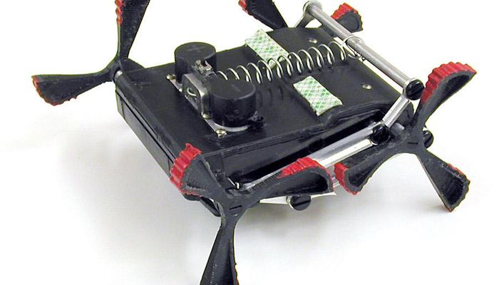
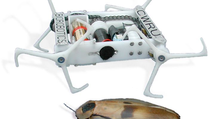
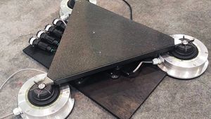
Mini-Whegs robots are similar in size and weight and have two axles with two three-spoke whegs each. A single propulsion motor drives both axles. The chassis consists of a rectangular frame that houses the main systems, including the drive train, steering components, batteries, and the onboard RC components. Jumping Mini-Whegs is designed specifically to demonstrate that jumping ability can be added to the smallest “Whegs” platform. It is very similar to the other Mini-Whegs robots, but includes an additional jumping mechanism and forgoes steering and radio control components. As the robot runs, the jumping mechanism slowly retracts, releases, and then repeats. The robot uses the same single drive motor and transmission used by other Mini-Whegs robots to simultaneously power both the running and jumping functions. An additional gear reduction was added to provide sufficient torque to wind the spring-activated jumping mechanism.
Leg Design
Legs Three-spoke whegs were developed to propel the full-sized Whegs robots. The spokes of each wheg are spaced 120 degrees apart and two whegs are mounted on each axle. Contralateral pairs of whegs are nominally positioned 60 degrees out of phase with each other. Whegs robots have a total of three axles, every 60 degrees out of phase with its neighbor. One motor drives all three axles via chains and sprockets so that Whegs robots walk in a cockroach-like nominal alternating tripod gait.
 Rendering of the Mini-Whegs IV front wheg and steering joint design.
Chassis and Drive Train
The rectangular frame of Mini-Whegs contains a single 1.2W Maxon DC drive motor with 67:1 planetary transmission, the drive train, steering components, batteries and control system. The frame itself consists of two Delrin side rails with aluminum cross-braces on the top and bottom. The side rails are precisely machined to support nearly every component inside the robot, including axle bearings, motor mounts, battery supports, and the steering servo and rack. The physical dimensions of the Mini-Whegs IV chassis are 9.0cm long by 6.8cm wide by 2.0cm thick with attached 3.6cm radius whegs. The robot’s mass is 146g, including batteries. Mini-Whegs robots have two axles connected to one drive motor via non-slipping stainless steel drive chains. This non-slipping drive connection is necessary because the correct phase offset between the front and rear axles must be maintained in order to achieve a nominal alternating diagonal gait. The use of one motor and chain drive to propel the robot has the additional advantage that all of the onboard power can be delivered to a single wheg when the others are slipping on the substrate.

Steering
The basic design of the steering mechanism for Mini Whegs is similar to the system in an automobile. Each front wheg rotates in a bearing, which is supported by a steering arm. A servo actuated sliding rack connects to the steering arms with a slot and pin. The steering arms pivot in mountings on the aluminum chassis cross braces to provide a steering motion. A rendering of the steering layout for Mini-Whegs IV is shown Since all four whegs are driven, the front axle must transmit power to the whegs and still allow for steering movement. We explored using flexible materials for this application in earlier versions of Mini-Whegs. As discussed in Section 2.1, these components were designed to serve the dual purpose of providing torsional compliance for automatic gait adaptation. Mini-Whegs IV forgoes axle-based torsional compliance for greater precision and strength. To provide a strong and reliable steering system for Mini-Whegs IV, a simplified universal joint was designed for each front wheg using no flexible components (Fig. 2). The joint consists of a ball at either end of the front axle inserted into a brass cup, which is mounted in the steering arm bearing. A pin attached to the ball slides in a slot in the brass cup to transfer torque while allowing the cup to pivot around the ball. Dimensions of steering arms and other components were designed to allow the maximum pivoting travel given certain clearance and servo travel limitations.
References
Describes how the robot climbs vertical fabric surfaces with Velcro®, crosses ceilings with Scotch® tape, and climbs steep concrete inclines with sharp spines and provides a test-platform for future adhesive materials such as dry adhesive tape.
Describes the methods and design, chassis and drive train, and steering. Describes the control system, operation, discussion, and future work.
Recommended Specs

Continue Reading
Researchers in the Department of Mechanical Engineering at Carnegie Mellon University have created the first legged robot of its size to run, turn, push loads and climb miniature stairs.

2 minutes read


How a hopping mouse and information theory could inform robotic locomotion.

4 minutes read


DEEP Robotics recently released its newest robotics technique, which is autonomous coordinated multi-robot exploration; the experiment is operated under a 3,000 m2 unknown environment with five Jueying X20 robot dogs.

2 minutes read