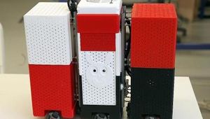
Hexapod robot
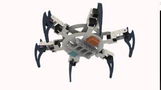
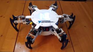
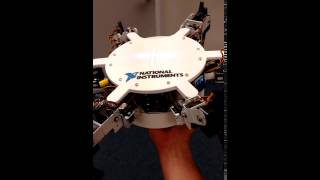
A walking and self-balancing hexapod robot. A biomimetic, six-legged robot, which emulates insect locomotion. The robot is a fully mobile Hexapod capable of multi-directional walking and self-balancing. The hexapod robot is a mechanical vehicle that walks on six legs. Since a robot can be statically stable on three or more legs, the hexapod robot has a great deal of flexibility in how it can move.
Overview
A biomimetic, six-legged robot, which emulates insect locomotion. The robot is a fully mobile Hexapod capable of multi-directional walking and self-balancing. The hexapod robot is a mechanical vehicle that walks on six legs. Since a robot can be statically stable on three or more legs, the hexapod robot has a great deal of flexibility in how it can move.
The robot has six legs, each consisting of three servo motors, for a total of eighteen. Mounting the other components onto this frame is not a trivial task. Most work went into mounting these components to allow for (a) robustness, (b) ease of replacement and (c) neat design.
Mechanical Design
Here are the components that needed mounting the hexapod.
- Lithium Polymer (LiPo) Battery
- Hitec Servo Motors (18)
- TP-Link WiFi Router
- Neopixel 8x8 LED Array
- Xsens IMU Orientation Sensor
- Power distribution circuitry
- Signal routing circuitry
Project is build on top of a pre-built hexapod frame, the Lynxmotion CH-3 frame.

Six legs, each consisting of three servo motors, for a total of eighteen. Mounting the other components onto this frame is not a trivial task. In fact a great deal of thought went into mounting these components to allow for (a) robustness, (b) ease of replacement and (c) neat design.
The LiPo battery, Xsens sensor and the Router mount to the bottom of the frame. To protect these components, I designed a battery holder and a bottom case for the hexapod, both 3D printed as bespoke parts. Here's how they all fit together.
The sbRIO, and various bespoke circuitry was mounted inside the hexapod between the top and bottom plates. On the top of the hexapod, the LED array was mounted.
Instructions
There are three key parts to this project, Mechanical Design, Electronics and LabVIEW Software.
Here is the overall system diagram:
All components are shown in blue, bespoke hardware is shown in orange. The system is powered by either an onboard Lithium Polymer (LiPo) battery or a mains power input (selected by a switch). This power input is then regulated by a power regulation board, providing appropriate voltages for the rest of the components on the hexapod.
A TP-link router is connected to the sbRIO to allow for wireless programming and operation, whilst an Xsens Orientation sensor is connected to one of the serial ports on the sbRIO to allow the hexapod to sense orientation. Signal routing circuitry is used to get the various digital signals from the sbRIO to the various system components.
NI Hexapod Build Guide
Being a prototype device rather than a final product, it should be noted that the build process for this robot is somewhat quirky and ill-defined. You will need to utilize your own initiative to complete parts of this robot. Also, for brevity, it is assumed you are familiar with some circuit manufacture techniques, such as solder reflow.
Electronics

Electronics was needed for this project to:
- Convert an unregulated 12V input voltage to a stable 5V for the motors, router, LED array and Xsens IMU.
- Route the multiple digital signals (20 in total) from the sbRIO to the motors, and LED array.
To achieve this, I designed the main board to mate directly with sbRIOs high-density IO (RMC) connector, along with three separate power regulation boards to be distributed across the chassis. Below is shown the RMC connector; 96 separate lines inside a surface mount socket (requires accurate placement for reflow soldering!)
Using three separate power regulation boards, rather than combining them with main board means that the motors cables can be easily accessed, and on the whole, makes the electronics more modular. Here is the electronic system diagram:

The Main Board (blue) and Power Regulation Boards (green), were both designed as printed circuit boards (PCBs), manufactured, soldered and tested.

This is the majority of the electronic infrastructure on the hexapod; routing the various signals, and regulating the DC power, for the system components. Ribbon cables are used to route the Motor PWM signals to the Power Regulation Boards, making the electronics modular and easy to remove/replace.

Software Overview
By far the most extensive part of this project is the software. Co-ordinating 18 motors to achieve a good quality overall movement is not easy and requires well-structured code. Below is the overall software architecture.

The software is divided across the three hardware platforms on the hexapod; The FPGA, RT Processor and Development Computer.
The FPGA is used for the laborious mathematical calculations for needed to perform inverse kinematics (converting XYZ robot leg positions to leg joint angles), and low-level digital signal generation. This frees up the RT Processor to do the higher level work; in this case generating the list of XYZ positions required to make the robot walk, or calculating desired body orientations based on sensed orientation.
To organise the code controlling the XYZ positions of six legs, I built my own object oriented set of drivers, humourous referred to as LEGmx. They make the process of writing 6 XYZ motor positions (that's 18 values) to an FPGA VI much simpler.

Essentially the FPGA acts almost like a bespoke hardware driver for the RT processor, easily performing the hundreds of calculations needed for control, saving millions of operating cycles for the RT processor. This kind of hardware setup is absolutely ideal for robotics applications, and is one of the key benefits of using the sbRIO.
A VI on the development computer runs a 3D simulation of the hexapod (based on imported STL files), and animates it based on the real angles sent from the RT processor via a global variable. The VIs running on the RT Processor are controlled via Front Panel Communication from the development computer.
References
Elaborate background information. Describes the electronic schematics, components used, and the software.
Project on the website of the initiator, National Instruments. Describes the project, the mechanical design, electronics, and LabVIEW Software. Also contains links to the mechanical, and electronic files.
Recommended Specs

Continue Reading
What's the difference of these two precision manufacturing techniques? This article will review on Cost Efficiency, Lead Time, Design Complexity, and Quality/Accuracy.


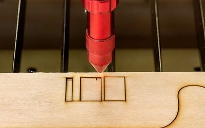
Laser cutting is the process of using a laser beam to vaporize, melt, or otherwise gradually remove material. Computer Numerical Control (CNC) laser cutting commonly uses optics, an assist gas, and a guidance system to direct and focus the laser beam into the workpiece.

2 minutes read

Micro-fabricated nozzle plates are used in various industries, such as inkjet printing, medical devices, and flow control. Manufacturing these nozzle plates requires precision and accuracy to achieve the desired performance. Several production technologies can be used to manufacture micro-fabricated metal nozzle plates, such as 3D printing, Laser Cutting, Micro Milling, Micro Punching, and Electroforming. In this article, we will introduce these production technologies, and illustrate how to find your preferred process for the production of micro-fabricated nozzle plates based on key features such as precision, customization, scalability, and material compatibility.