The Role of Reinforcement Geometry in Boosting 3D-Printed Part Performance
Explore how fiber length, shape, and distribution impact mechanical properties beyond just material choice

09 Jul, 2025. 7 minutes read
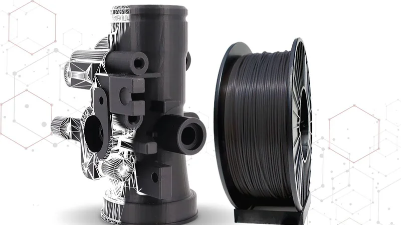
Additive manufacturing has changed the way engineers design and produce high-performance components[1]. This is further improved by reinforcing filament materials, such as carbon fiber. Its ability to enhance a base material's strength and thermal stability has made it a go-to additive in high-performance filament formulations.[2]
However, it's not just about the reinforcement material. The geometry of the carbon fiber reinforcement, such as fiber length, aspect ratio, and distribution, also plays a critical role in defining the final part's properties.[3] These geometric variables determine how the fibers interact with the polymer matrix, influence flow behavior during printing, and affect the strength of the part post-processing.
Leading this space is 3DXTECH, an advanced materials manufacturer based in Michigan. With a broad portfolio of carbon fiber-reinforced materials, 3DXTECH offers high-performance filaments, including PEEK, PEKK, and Ultem, alongside custom formulations tailored to specific project needs.
Understanding the Types of Carbon Fiber Reinforcement
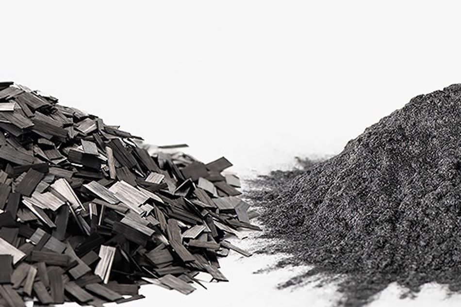
To fully grasp how reinforcement geometry affects part performance, we first need to understand the primary types of carbon fiber fillers used in additive manufacturing: chopped and milled carbon fibers. Each has distinct characteristics, manufacturing processes, and applications.
Chopped Carbon Fiber
Definition and Characteristics
Chopped carbon fiber consists of continuous carbon filaments cut into short lengths, typically ranging from a few millimeters to a few centimeters. These fibers are then integrated into thermoplastics like PLA, ABS, or nylon to enhance mechanical properties. Chopped carbon fiber offers superior mechanical strength even at high temperatures, making it a go-to choice for high-performance applications. Its low coefficient of linear thermal expansion ensures dimensional stability under thermal stress. Lastly, its low moisture absorption makes it suitable for harsh environments.
Manufacturing Process
The process starts with polyacrylonitrile (PAN) or pitch, which are widely used for making carbon fibers. In the next step, known as carbonization, the material is exposed to high temperatures in an oxygen-free environment. Once carbonized, the fibers are cut to precise lengths using specialized rotary cutters.[4] These short fibers are then compounded with a thermoplastic resin, such as polycarbonate or nylon, to create a filament suitable for fused deposition modeling (FDM) or fused filament fabrication (FFF) 3D printing. The compounding process ensures uniform fiber distribution, which is critical for consistent mechanical performance.
Applications
Thanks to its high strength-to-weight ratio, chopped carbon fiber is widely used in aerospace for brackets and structural components, and in automotive for lightweight parts. Its ability to withstand high temperatures and chemical exposure makes it ideal for demanding environments like oil and gas or defense applications.
Milled Carbon Fiber
Definition and Characteristics
Milled carbon fiber consists of finely ground carbon particles, typically less than 1 mm in length. Unlike chopped fibers, milled fibers resemble a powder, offering unique advantages in dimensional stability and wear resistance. They also exhibit excellent resistance to a wide range of chemicals, including automotive fluids and fully halogenated hydrocarbons, making them suitable for precision components.
Manufacturing Process
Milled carbon fiber is produced by grinding continuous carbon fibers using hammer or ball milling processes.[5] The resulting fine particles are then blended with a resin matrix to create a composite filament. This process allows for a higher degree of uniformity in the filament, which translates to improved printability and surface finish.
Applications
Milled carbon fiber is commonly used in applications requiring high precision and smooth surface finishes, such as aerospace components and electronics enclosures. Its ability to maintain dimensional accuracy makes it a preferred choice for parts where tight tolerances are critical.
Comparison of Chopped vs. Milled Carbon Fiber
The differences between chopped and milled carbon fibers significantly impact the performance of 3D printed parts. Below is a detailed comparison of their key properties to help engineers evaluate which reinforcement type suits their project needs.
Property | Chopped Carbon Fiber | Milled Carbon Fiber |
Tensile Strength | High | Moderate |
Dimensional Accuracy | Moderate | High |
Flexural Strength | High | Moderate |
Surface Finish | Rough | Smooth |
Aspect ratio | High | Low |
Printability | Moderate | Excellent |
Shape | Rod like | Fine powder |
Thermal Conductivity | High | Moderate |
Moisture Absorption | Low | Very Low |
If you're printing a bracket or a structural load-carrying part where maximum stiffness and high-temperature strength are key, chopped carbon fiber is a better option. If you're designing an electronics housing or tooling insert where tight tolerances, excellent surface finish, and dimensional reliability are essential, milled carbon fiber is the superior choice.
Comparison: 3DXMAX PC vs CarbonX PC+CF
To show how reinforcement geometry affects material performance, we are going to compare two polycarbonate-based filaments from 3DXTECH: 3DXMAX PC and CarbonX PC+CF. While both share the same base polymer, the addition of carbon fiber in CarbonX PC+CF significantly changes how the material performs.
3DXMAX PC
3DXMAX PC is a high-performance polycarbonate filament made using Lexan resin from SABIC.[6] Designed for high-heat applications, it delivers outstanding mechanical strength, thermal resistance, and a clean surface finish for detailed, high-quality prints. This filament is compatible with FDM and FFF 3D printers equipped with a heated bed and heated build chamber. It prints reliably within an extruder temperature range of 280 to 310°C. It maintains excellent thermal stability owing to its high glass transition temperature of 147°C. Its amorphous molecular structure results in low, near-isotropic shrinkage when printed in a minimum 90°C chamber, which helps ensure dimensional accuracy when printing complex geometries. It is also known for impressive ductility, high impact resistance, and a virtually odorless printing process.
CarbonX PC+CF
CarbonX PC+CF is a high-performance 3D printing filament made from carbon fiber reinforced polycarbonate. The addition of chopped carbon fiber boosts stiffness, dimensional stability, and strength. Its amorphous structure minimizes shrinkage and ensures near-isotropic mechanical properties, even in geometrically complex parts. CarbonX PC+CF prints within a wide temperature window of 280 to 310°C and requires a heated bed for optimal adhesion, as well as a heated build chamber. With a glass transition temperature of 127°C, this material offers some of the highest thermal performance available in 3D printing. A hardened steel nozzle with a minimum diameter of 0.4 mm is recommended to handle the abrasive carbon fiber content. Despite its industrial-grade performance, the material emits very little odor during printing, making it well-suited for professional environments focused on quality and reliability.
The following comparison between 3DXMAX PC and CarbonX PC+CF highlights the impact of carbon fiber reinforcement at a glance:
Property | 3DXMAX PC | CarbonX PC+CF |
Density (g/cc) | 1.2 | 1.36 |
Tensile Strength (MPa) | 62 | 73 |
Tensile Modulus (MPa) | 2410 | 6980 |
Tensile Elongation (%) | 7 | 2.1 |
Flexural Strength (MPa) | 78 | 85 |
Flexural Modulus (MPa) | 2200 | 6540 |
Glass Transition Temp (Cel) | 147 | 127 |
Deflection Temp (Cel) | 135 | 119 |
Surface Resistance (Ohm/sq) | > 10^13 | 10^9 |
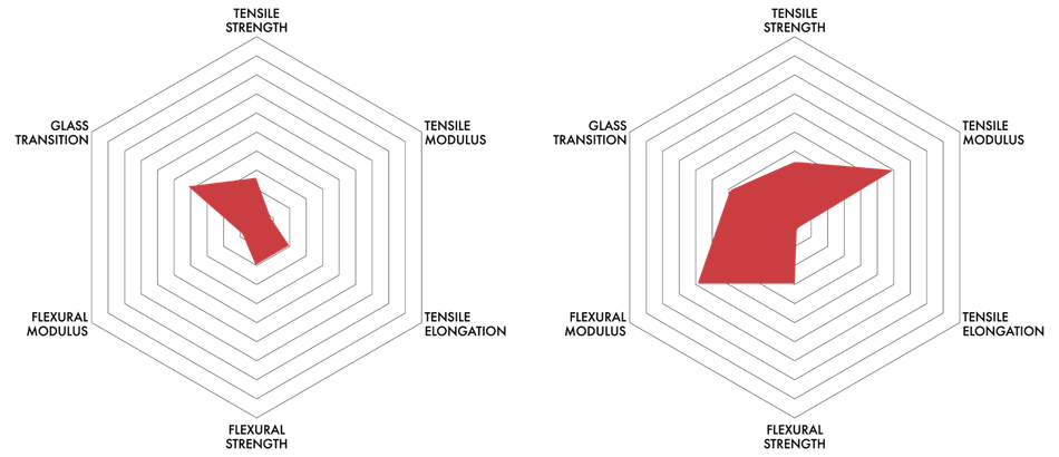
Graphical representation of PC vs PC+CF performance.
Comparison: MAX-G PETG vs CarbonX PETG+CF
PETG is another popular base material known for its toughness, ease of printing, and chemical resistance. To further establish how carbon fiber reinforcement enhances performance, let’s pit two PETG-based filaments, MAX-G PETG and CarbonX PETG+CF, against each other.
MAX-G PETG
MAX-G PETG is a durable material with excellent strength and flexibility. Made from FDA-approved base resin, it offers superior chemical resistance compared to PLA and ABS. This material stands out for its low moisture absorption, which is nearly three times lower than ABS. It has a wide processing range of 230 to 260°C. The amorphous structure ensures low, near-isotropic shrinkage, helping maintain dimensional accuracy throughout complex prints.
MAX-G PETG resists harsh chemicals such as isopropyl alcohol and produces very little odor during printing. It's a go-to solution for engineers who need a balanced combination of strength, durability, and printability.
CarbonX PETG+CF
CarbonX PETG+CF is a carbon fiber reinforced PETG filament for enhanced strength, stiffness, and thermal performance. Reinforced with engineering-grade carbon, this formulation delivers superior mechanical properties and an excellent surface finish. It features an amorphous structure that minimizes shrinkage and offers near-isotropic behavior. It absorbs about three times less moisture than ABS and emits very little odor during printing.
The material has a wide processing window of 230 to 270°C. It requires a hardened steel nozzle with a minimum diameter of 0.4 mm.
CarbonX PETG+CF is ideal for structural components that need to withstand a moderate level of stress. It is particularly well suited to find a balance between lightweight construction, superior surface finish, and easy printability.
Property | MAX-G PETG | CarbonX PETG+CF |
Density (g/cc) | 1.2 | 1.34 |
Tensile Strength (MPa) | 45 | 56 |
Tensile Modulus (MPa) | 1650 | 5230 |
Tensile Elongation (%) | 24 | 3 |
Flexural Strength (MPa) | 72 | 80 |
Flexural Modulus (MPa) | 1600 | 5740 |
Glass Transition Temp (Cel) | 80 | 80 |
Deflection Temp (Cel) | 70 | 77 |
Surface Resistance (Ohm/sq) | >10^13 | >10^9 |
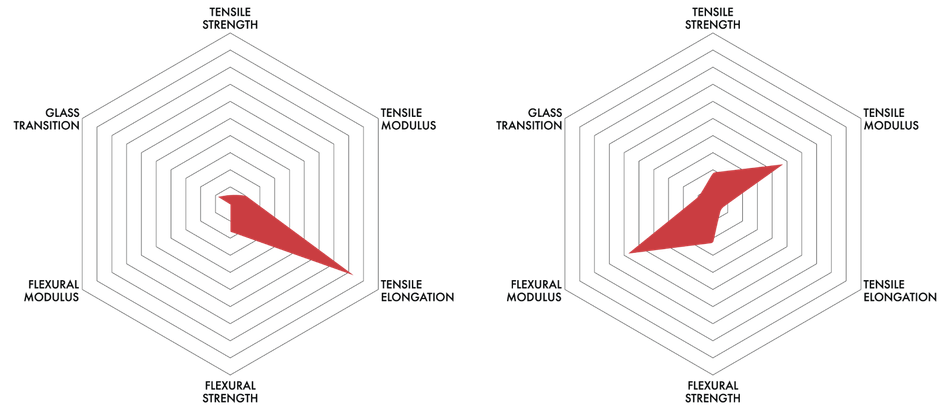
Graphical representation of PC vs PC+CF performance.
How 3DXTECH Helps Customers Choose the Right Filament
Choosing the right filament for your application isn't always straightforward. With a wide range of base materials and reinforcement types on the market, zeroing in on the right one can be time-consuming. That’s where 3DXTECH sets itself apart. More than just a materials supplier, the company acts as your technical partner. 3DXTECH works closely with engineers to match reinforcement type and formulation to your performance requirements. Their technical support team evaluates several parameters before making recommendations:
Application requirements: Load-bearing, environmental resistance, chemical exposure.
Printer capabilities: Nozzle temperature, heated bed availability, and chamber conditions.
Desired properties: Strength, stiffness, dimensional accuracy, or finish.
The company also provides custom formulations for customers with niche or complex needs. Whether you are designing a prototype for the aerospace sector or producing functional parts for robotics, 3DXTECH ensures the material aligns with performance expectations. In addition, since all 3DXTECH’s materials are manufactured in the United States, customers are protected from supply chain disruptions and the highly volatile tariff situation.[7]
Conclusion
For engineers pushing the limits of additive manufacturing, understanding reinforcement geometry is crucial. The shape, size, and distribution of carbon fibers influence how these materials behave under stress, heat, and during the printing process.
Chopped fibers offer high tensile and flexural strength, making them ideal for load-bearing parts that require performance under stress. Milled fibers, with their fine particle structure, offer excellent dimensional stability and printability, especially when tight tolerances and smooth finishes are important.
Carbon fiber reinforcement doesn’t just make materials stronger; it enhances thermoplastics so they can meet demanding specs for industrial use. In sectors such as aerospace, automotive, and robotics, CF-filled filaments unlock new design possibilities.
To get the most out of your next design, choose the reinforcement that matches your performance goals. Visit 3DXTECH.com to explore detailed material specs, request samples, or connect with a technical expert who can help you select the right filament for your application.
References:
1. https://www.sciencedirect.com/science/article/pii/S2666496825000226
2. https://ultimaker.com/learn/carbon-fiber-3d-printing-revolutionizing-additive-manufacturing/
3. https://www.sciencedirect.com/science/article/pii/S2666912922000277?
4. https://advancedcarbonscouncil.org/blogpost/2151389/507386/The-Process-Behind-Chopped-Carbon-Fiber
5. https://www.sciencedirect.com/science/article/abs/pii/S1359835X2200430
6. https://www.sabic.com/en/products/polymers/polycarbonate-pc/lexan-resin
7. https://www.3dxtech.com/blogs/featured/tariffs-drive-urgent-need-for-u-s-based-suppliers-2