Simulation Moves to the Front of Vehicle Body Development
Starting with CAE guidance provides engineers with early concept confidence and adaptive designs.

13 Oct, 2026. 5 minutes read
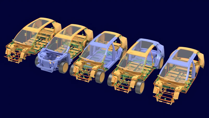
Body-in-white (BIW) development is one of the most consequential phases of vehicle design, carrying an outsized impact on driving range and total material cost. But despite its importance, BIW comes extremely early in the design cycle, often well before designers have meaningful data to work with.
Historically, teams have used relatively slow computer-aided engineering (CAE) to confirm BIW layouts and load-path decisions post-design. But as program timelines shorten and margins for error shrink, engineers need CAE so they can quickly rebuild and rerun at any data-fidelity level.
That’s why Siemens built its body development workflows in Simcenter™ Hypermesh™: to put CAE guidance in front of the decision, while the design can still adapt. Moving simulation to the front of a program, Simcenter Hypermesh changes what engineers can commit to and when.
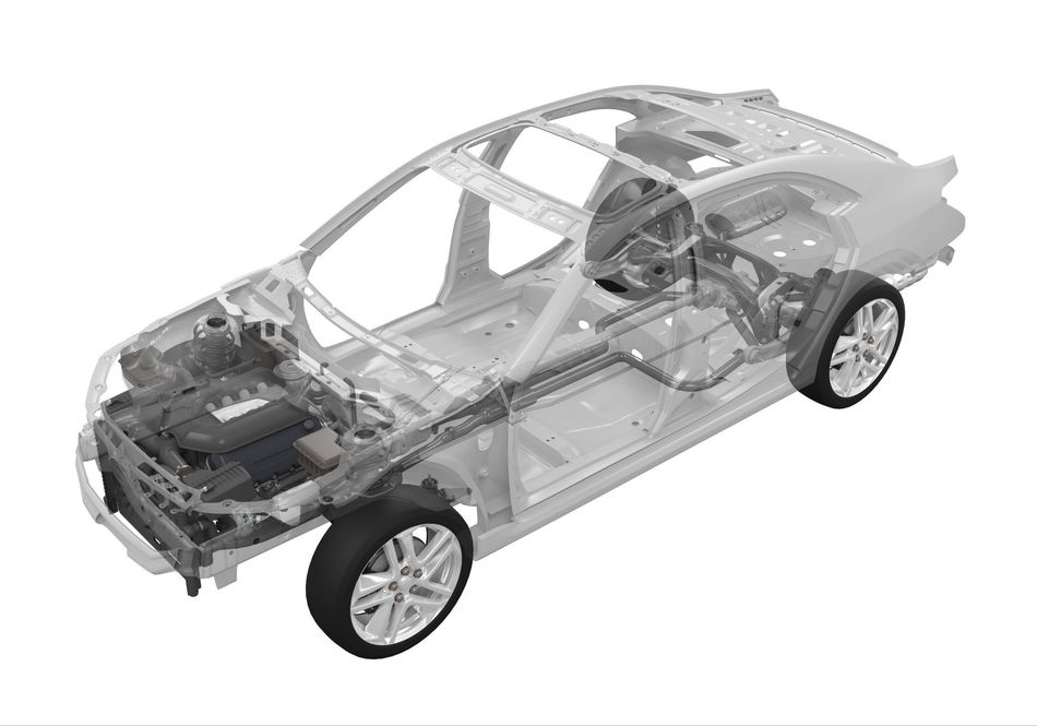 Body engineering challenges. Source: Siemens.
Concept-Phase Decisions and CAE
Engineers begin the BIW concept phase with a wide field of choices, each landing somewhere different on the spectrum of mass and cost. At this point, the goal is to narrow the options to the lightest, cheapest structure that still carries the loads, which ultimately necessitates quick structural feedback on every candidate the team wants to compare. For a broader perspective on how body engineering is evolving into a structural intelligence layer, explore this expert discussion on faster, more confident engineering decisions.
Although CAE is the historical solution, its workflows are too slow to keep up. With CAE, analysts need detailed geometry to build a finite element model, but at the concept stage, this detail doesn’t yet exist. Even once that geometry is available, engineers using CAE spend so long preparing and meshing the model that they can realistically evaluate only a handful of combinations.
Beyond the speed discrepancy, CAE also creates a chicken-or-the-egg situation between model detail and design data maturity. A fully detailed finite element model requires a proven geometry, but engineers only prove that geometry after making the layout decision the model was supposed to inform. A coarse model, on the other hand, might return an answer too unsubstantiated to justify a platform decision.
In most cases, designers will protect themselves by over-designing and adding material wherever the analysis feels uncertain. In turn, those margins tend to push the body past its weight target and cost the vehicle range and efficiency.
The Limits of Traditional Simulation Processes
One challenge in the current CAE workflow is that teams often model parts that don’t exist yet. An analyst modeling the space around an engine, for example, must wait on geometry from suppliers, who are still quoting the work. In response, the designer will use placeholders and rework their models when the real data arrives.
That revision is then only the first of many. Every design change sends them back to the CAD tool to reintegrate, remesh, and rerun the part and its analysis. On an intricate body model, that sequence can stretch a single iteration into days or weeks. And beyond time, detailed finite element analysis (FEA) adds its own computational bill to the project budget.
As a result, teams ration variants accordingly. Some engineers run fewer optimization studies than the design warrants, and some skip the optimization phase entirely, forfeiting the mass savings the phase is meant to find.
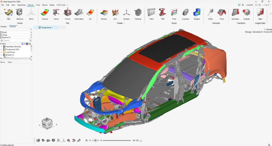 CAD model. Source: Siemens.
Fidelity That Tracks Design Maturity
The way out starts with matching the model to the moment. Engineers need model accuracy that steps up as design data matures: free-form layout studies while the architecture is still open, and manufacturable joint detail once sections and materials are settled. A process built this way depends only on the inputs available at each stage.
The model’s fidelity measures also need to be mixable. Programs mature unevenly, with one section being close to production while another is nearly untouched. The best solution will let designers combine models of different measures in a single study, so they can progress on different subsystems in parallel without waiting for other sections to catch up.
The Ideal Model Iteration Process
Matched fidelity only pays off if engineers can change the model as fast as they change their design. That means building and editing design spaces directly in the simulation environment, without a round trip through CAD for every revision.
Designers must also keep the setup manageable as the model grows. To do this, they need a design tool that separates the global design space (i.e., overall body structure) from the local design spaces (i.e., individual components). That way, designers can rework one component without impacting others.
Finally, the ideal model iteration process keeps per-iteration cost low. Designers should have access to tools like reduced-order models (ROMs) that strip a detailed structure down, keeping parameter variation cheap enough to repeat dozens of times. Simulation teams should also be able to work the other direction and rebuild detailed geometry from simple inputs such as line models and section profiles.
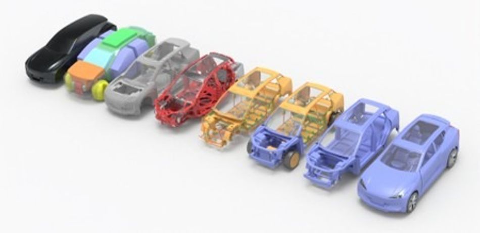
Simcenter Hypermesh and Concept 123
To bring the ideal workflow to life, Siemens offers Simcenter Hypermesh: a CAE pre- and post-processing environment to build, mesh, and optimize structural models without leaving simulation for CAD.
Importantly, Siemens built Simcenter Hypermesh around a three-tier approach called Concept 123 (C123).
C1 identifies the optimal structural layout using free-form models.
C2 sizes and optimizes idealized sections and joints using low- or mixed-fidelity models.
C3 optimizes and sizes manufacturable sections and joints using high-fidelity models.
And, to address mixability, Siemens designed C123 without a fixed sequence. Teams can start where their data starts and blend models from all three tiers anytime a program matures unevenly. With Simcenter Hypermesh, the simulation process follows the design instead of dictating the order in which engineers work. See how an optimization-led, multi-physics approach helps engineering teams evaluate trade-offs earlier in the on-demand webinar, “Redefine automotive body engineering excellence”.
Direct Model Building in Simcenter Hypermesh
These capabilities are all a part of the tool itself. In the design space, Simcenter Hypermesh gives engineers tools to directly create and edit regions, so they can set up a topology optimization run and revise it later without reverting to CAD. And, because designers can edit those regions in place, they no longer have to rebuild entire models from scratch for every minor iteration. Global design space setups cover the body's overall structure, while local setups cover individual components such as a B-pillar reinforcement, so reworking that one reinforcement leaves the rest of the body alone.
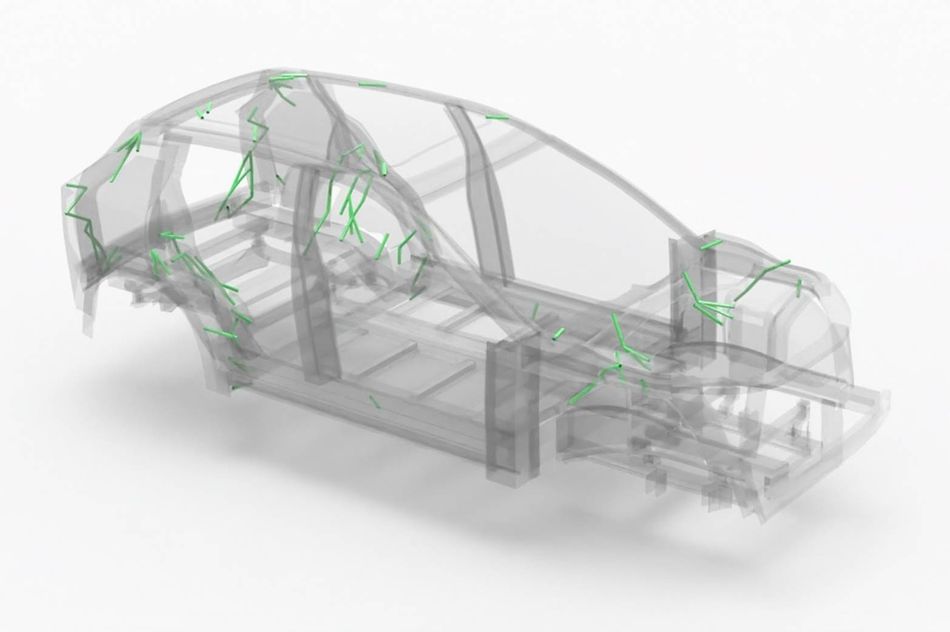
To make the process more affordable, Simcenter Hypermesh offers skeleton modeling: a workflow that simplifies a finished model instead of a design region. With it, engineers can simply point the workflow at a donor CAD or FEA model and get back a ROM made of the structure's joints, members, and panels. As a result, each run costs so little that teams can freely test a multitude of variants.
The tool also includes a CAD-like sketcher that engineers can use to reconstruct skeleton geometries. Simply draw sections and profiles, then grow detailed geometry from that line data. When a ROM study points to a promising section, designers can develop it in place, so the result returns to the design without another trip through CAD.
Designing Before Production
Electrification and software content will keep pushing structural commitments even earlier in the vehicle program, and those commitments will keep changing after teams make them. In that environment, engineers will need simulation that answers quickly and at whatever fidelity the data supports.
With Siemens’ Simcenter Hypermesh, engineers finally have a tool that matches their needs. With it, the concept phase stops being a gamble and starts being a place where teams design with evidence and confidence.
Learn how an integrated body engineering approach can help teams balance weight, performance, safety, cost, and manufacturability from the earliest development stages in the ebook, “Redefining body engineering excellence”.