Reducing the noise emission from an aircraft engine at its source
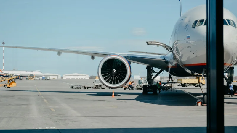
As a result of a constant increase in the number of flights, aircraft noise is becoming a major source of noise-induced annoyance. This article lists down some of the sources contributing to it and proposes possible solutions for mitigating the problem.
This article is a part of our University Technology Exposure Program. The program aims to recognize and reward innovation from engineering students and researchers across the globe.
Current state of aircraft noise pollution
When someone is asked, “Are you often annoyed by aircraft noise?”, the answer is likely a resounding “YES”. If you happen to live within a few kilometres from an airport (think of the neighbourhoods around Schiphol for example), aircraft noise is likely to be a major source of noise-induced annoyance. However, how loud is “too loud” exactly? In a recent survey conducted by the Federal Aviation Administration (FAA) in the United States, it appears that once the average day-night noise level rises above 50 dB (decibels), the percentage of highly annoyed respondents increases dramatically as portrayed in Figure 1.
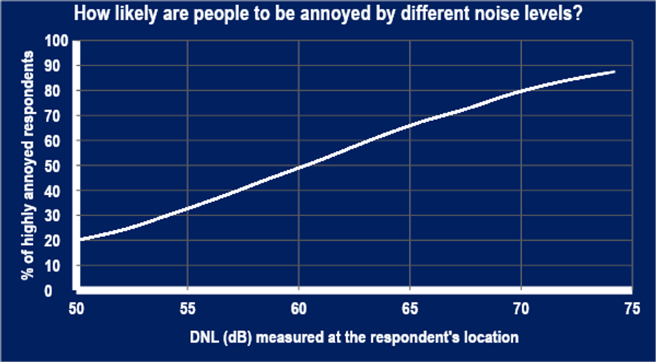
For reference, the average noise level in a quiet classroom is around 25-30 dB, a regular vacuum cleaner often produces noise as high as 75 dB, and a noise intensity at 50–55 dB is roughly equivalent to that of a household refrigerator. It would be unlikely for someone to sleep comfortably or to relax near a refrigerator or a running vacuum cleaner, right?
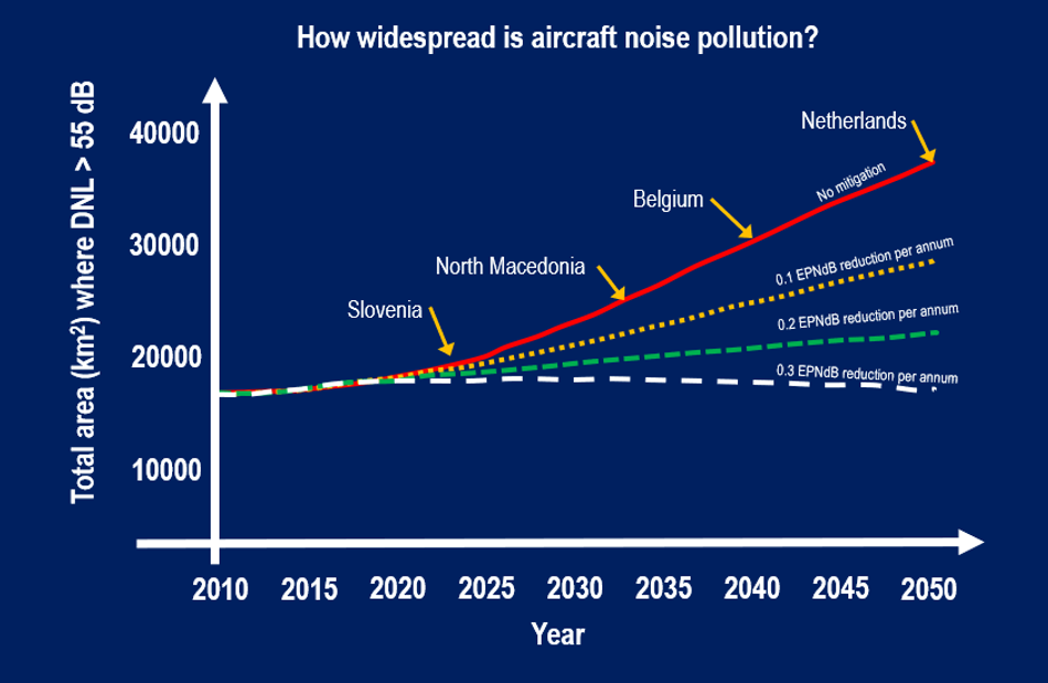
It is unfortunate that the impact of aircraft noise pollution is becoming more widespread following a research of ICAO (International Civil Aviation Organisation) research (see Figure 2). Without further noise reduction effort on individual aircraft, there could be a region as wide as the Netherlands on this planet by 2050 where the populace is regularly subjected to aircraft noise annoyance. It is expected the aircraft manufacturers must strive to achieve 0.3 EPNdB (effective perceived noise level in decibel) of noise reduction each year to reverse the trend. Of course, this necessitates continuous development of new technology and other forms of innovation.
The industry has, in fact, achieved great strides in terms of aircraft noise reduction. Modern jetliners operating today are hundreds, if not thousands, times quieter than their first-generation ancestors. This trend is illustrated in Figure 3 which shows the EPNL (effective perceived noise level – a metric used in aircraft noise certification) for different aircrafts at the time they were certified.
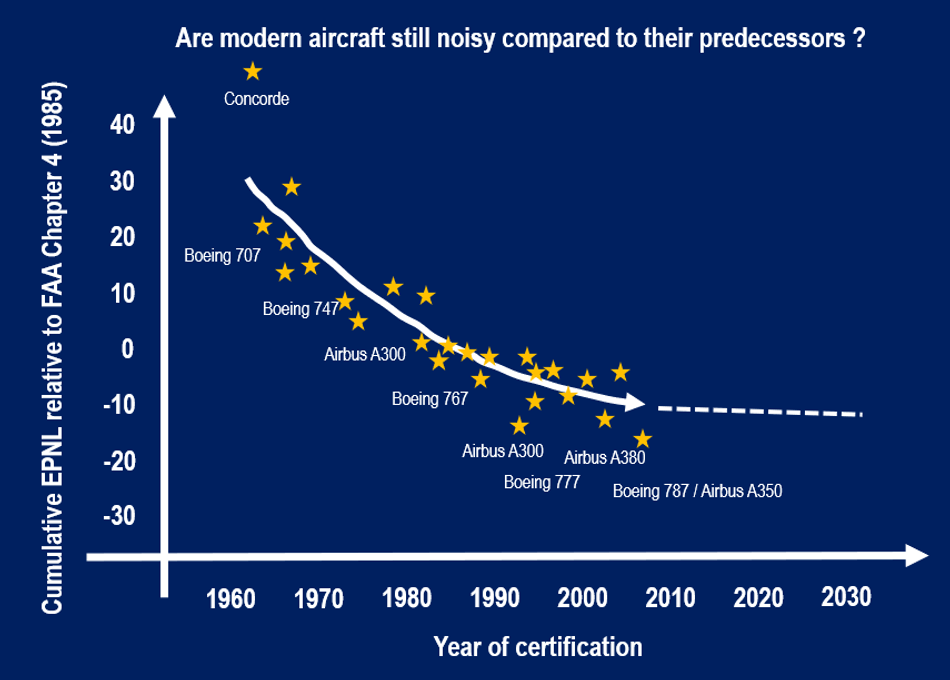
It should be noted that decibel is a unit for sound intensity in the logarithmic scale. This means that a 3 dB reduction corresponds to halving the sound intensity, whereas 10 dB reduction corresponds to 90% of reduction in the sound intensity. Therefore, the figure implies that the noise intensity emitted by a modern Boeing 787 Dreamliner is only 1/3000th of that of Boeing 707. More recently, however, the trend has slowed down evidenced by the “flatter” slope of the curve.
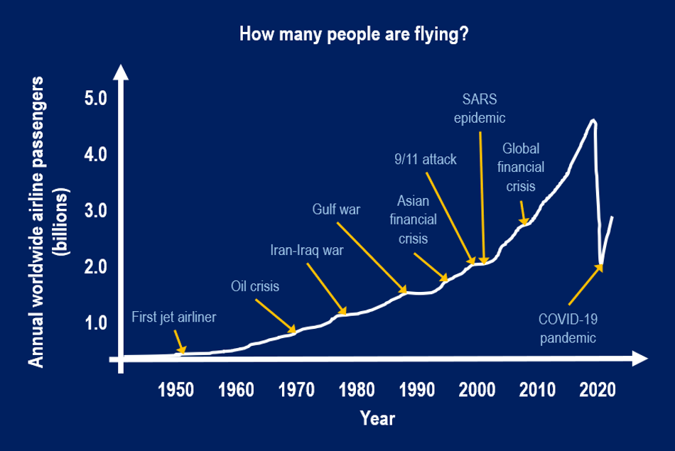
If modern aircrafts are already much quieter than ever before, then why is the impact of aircraft noise pollution becoming more widespread? Let us investigate the opposite end of this issue: the number of flights. Figure 4 suggests that the demand for civilian flight rises steadily despite setbacks introduced by adverse global events, such as economic crises and worldwide pandemic. The increase in the number of flights might have outpaced the present noise mitigation efforts, exacerbating the impact of aircraft noise pollution. Hence, novel technology and innovations will be necessary to ensure that the ongoing trend can be reversed in the future.
Noise sources in an aircraft
For many, the presence of an aircraft is often associated with “whooshing” and “whining” noises, which are in fact the noise coming out from the engines. Unsurprisingly, an aircraft engine, such as the widely used turbofan, is still one of the loudest noise sources.
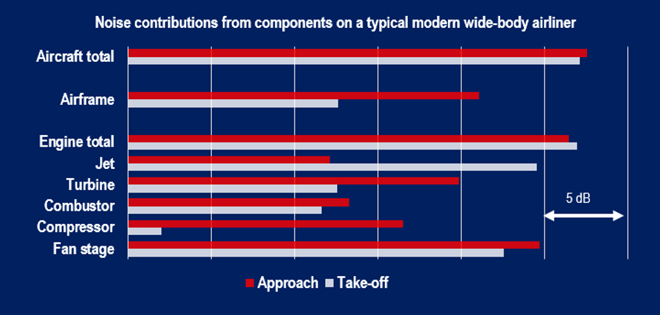
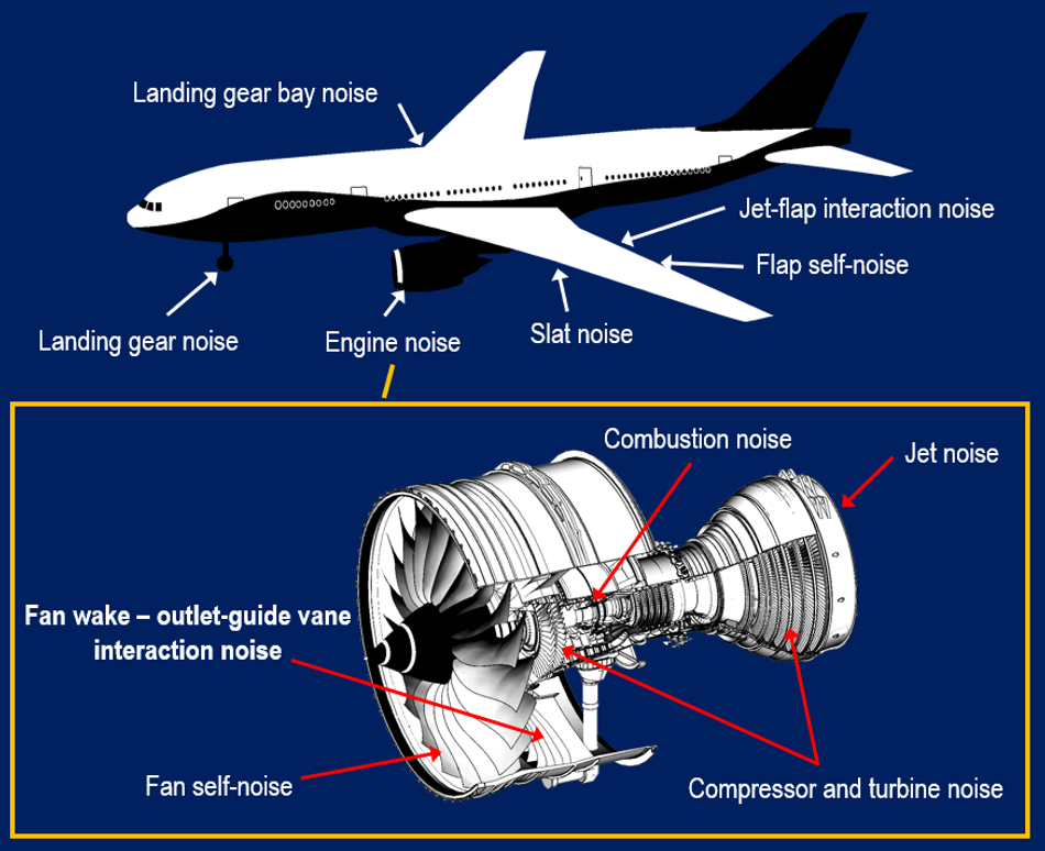
This is clearly shown in Figure 5, although it is worth noting that the airframe (i.e., fuselage, wings, and landing gears) also generates a fair amount of noise. The turbofan itself is a complex piece of machinery in which multiple noise generation mechanisms are found, such as the chaotic flow structures (turbulence) in the jet behind the engine. The jet noise used to be the main noise contributor on early airliners (e.g., Boeing 707). However, a modern turbofan generates a lower jet velocity to mitigate jet noise emission, and most of the thrust is achieved by using a large fan to drive a massive amount of air through the engine. In doing so the engine efficiency also becomes higher, and thus, there is a trend of increasing turbofan diameter over the years. Unfortunately, as the fan becomes larger, the noise contribution from the entire fan stage is also becoming more dominant (see in Figure 5).
One of the relevant noise mechanisms in the fan stage is the interaction between the fan wake and the outlet-guide vanes (OGVs). The OGVs are non-moving blades installed downstream of the fan to straighten the swirling motion induced by the rotating fan. As the fan blades rotate at several thousands of rotations per minute, they leave trails of turbulent wake behind, which would impinge the OGV downstream. This phenomenon results in unsteady compression and expansion in the flow field surrounding OGV surface, which is subsequently radiated as sound. To combat noise emission from the fan stage, the inner wall of a turbofan is often equipped with sound-absorbing liners. As the design of modern turbofans incorporates wider diameter, the surface area available for the liners is expected to be more limited to minimise excess weight. Therefore, it is reasonable to introduce a noise mitigation technique directly at the source in pursuit of a quieter aircraft engine.
Fan wake-OGV interaction noise mitigation using porous edge modification
The fan wake-OGV interaction is an example of turbulence-induced noise mechanism, which refers to the generation of sound due to the blockage of a turbulent flow field by a solid object. The keywords here are “blockage” and “solid”, which implies that if a turbulent flow field encounters an object that is “less solid”, and therefore imposes “less blockage”, the radiated noise intensity would be less as well.
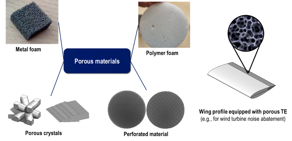
A porous material, which allows air flow to permeate through itself, appears to be a good fit for this purpose. There are many examples of porous materials, such as metal foams and perforated shells as depicted in Figure 6. These materials are often characterised by porosity (i.e., the volume proportion inside the material that is occupied by empty spaces) and permeability (i.e., the measure of “easiness” for flow to permeate across).
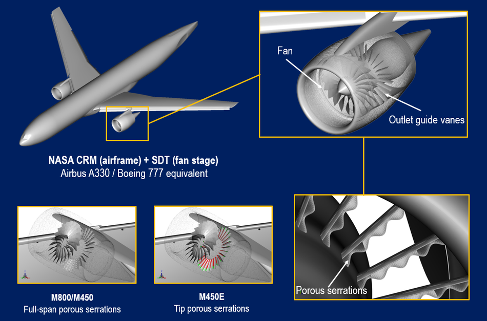
In a recent study, the application of porous material for aircraft noise reduction has been demonstrated using a computer simulation. The simulation considers an aircraft model based on a combination of NASA High-Lift Common Research Model (CRM) airframe and Source Diagnostic Test (SDT) turbofan fan stage. The velocity of the aircraft and the rotational speed of the fan correspond to a scenario in which the aircraft is approaching an airport. The forward segment of the OGV is modified using a porous leading edge with a sawtooth (serration) shape. The usage of serration shape generates smaller swirls around the porous surface, which further enhances the noise reduction capability by interfering with the coherence of noise scattering along the span of the leading edge. Two types of OGV modifications have been investigated: 1) the full-span porous leading edge (M800 and M450 – the higher number indicates higher porosity), and 2) the tip-only porous leading edge (M450E). In the latter, the OGV leading edge is porous only at the green region while the red region is completely solid.
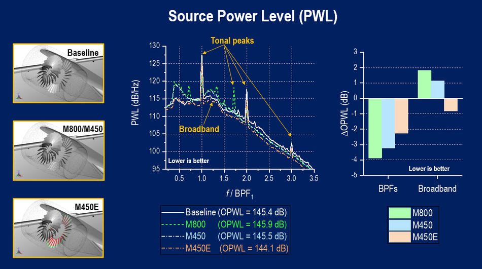
By employing a computational technique referred to as aeroacoustics analogy, it is possible to predict the far-field noise emitted by the aircraft model. Figure 8 shows the differences in the sound power level (PWL) produced by the different configurations. The graph on the left shows the distribution of the PWL at different frequencies. Note that the frequency axis is normalized by the first blade-passage-frequency (BPF), which is equal to the multiplication between the number of fan blades and the fan rotational speed. The sound produced by the aircraft model can be characterized by the tonal peaks, mostly corresponding to the multiples (harmonics) of BPF1, on top of the broadband base. Subsequently, the PWL spectra can be reconstructed into sound signals by employing auralisation technique.
The bar chart at the right side of Figure 8 shows the effect of the porous OGV treatment on the sound power level. The full-span porous leading-edge treatment (M800 and M450) substantially mitigates the tonal peak, but the broadband noise component is enhanced. Therefore, the total PWL (OPWL) values for both configurations have barely changed from the baseline. These effects are also proportional to the porosity (recall that the porosity of the M800 treatment is higher than that of the M450 one). Limiting the porous treatment near the blade tip (M450E) leads to a net OPWL reduction, since both the tonal and broadband noise components are both abated.
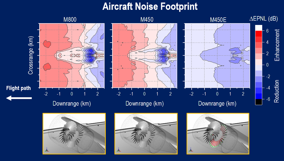
How do the different OGV treatments affect listeners on the ground? This can be examined using the aircraft noise footprint that has been computed using the auralisation technique as in Figure 10. Having the full-span porous OGV modification (M800 and M450) leads to a relatively large noise reduction downstream of the aircraft, but the ground noise level is enhanced in front of it. Conversely, the tip-only porous OGV treatment (M450E) achieves net noise reduction (between 1 – 3 dB) all around. This clearly shows that the porous leading-edge treatment has to be carefully designed and integrated to produce the desirable outcome.

What happens next
What happens next is anybody’s guess at this point, but the usage of porous material for aircraft noise mitigation can be considered promising as demonstrated in this study. Future investigations are still necessary to identify the relationship between the physical aspects of a porous material and their impacts on turbulent flows and sound generation. Some researchers have begun to employ advanced computing tools, such as machine-learning, to help with design optimization.
Hence, experimental and computational works are expected to remain indispensable for the upcoming years. Once the characteristics of a porous material application are better understood, it would be possible to manufacture tailor-made porous parts for different aircraft components, thanks to the advancements in additive manufacturing (e.g., 3D-printing).
Acknowledgement
The content of this article has been derived from a recent research paper of the author’s “A Numerical Study on Aircraft Noise Mitigation Using Porous Stator Concepts” published in MDPI Aerospace. The author acknowledges all co-authors who are also members of the Aeroacoustics Research Group at Delft University of Technology, Netherlands. The research has received funding from the European Union’s Horizon 2020 research and innovation program under the Marie Skłodowska-Curie grant agreement No. 722401.
About the University Technology Exposure Program 2022
Wevolver, in partnership with Mouser Electronics and Ansys, is excited to announce the launch of the University Technology Exposure Program 2022. The program aims to recognize and reward innovation from engineering students and researchers across the globe. Learn more about the program here.