Quasioptics for Increasing the Beam Efficiency of Wireless Power Transfer Systems
A student article explaining how quasioptical framework is advantageous for developing radiative wireless power transfer systems with high efficiency.

07 Aug, 2022. 17 minutes read
This article is a part of our University Technology Exposure Program. The program aims to recognize and reward innovation from engineering students and researchers across the globe.
The highest beam efficiency in a wireless power transfer (WPT) system that uses focusing components was 51%. Achieved by William Brown in 1964, it used a ≈ 3 m diameter reflector for a transfer distance of 7.62 m. This record was unbeaten for 58 years until now, as we present a system that surpasses Brown’s work by 25%. Using the quasioptical framework for reducing spillover losses in WPT, we present a double-reflector system that achieved a higher beam efficiency than the state-of-the-art, when taking into account the system components. The transmitting and receiving antennas were 3D-printed conical smooth-walled horn antennas, specially designed for this system. The theoretical analysis enabled the design of a five-meter system, whose energy focus location has been experimentally verified. Following this successful measurement, the complete system was experimented upon, whose results are here described, enabling a high beam transfer efficiency of 63.75%, validating the theoretical results obtained previously. Additionally, the advantage of using quasioptics in radiative wireless power transfer applications is discussed, as well as the sensitivity of its systems by analyzing how the efficiency changes with variations of different parameters. Finally, a comparison of this system with the state-of-the-art is done by the proposal of new figures-of-merit, relating the systems’ physical dimensions and beam efficiency. Through them, it becomes clear that our system outperforms the previous works in terms of the beam efficiency achieved when taking into account the system components used. Furthermore, this research is a paradigm shift by presenting a promising path for future WPT research through quasioptics, one that may lead to developments of such high efficiencies that will potentially enable commercial application of this technology in solving power supply issues in our society.
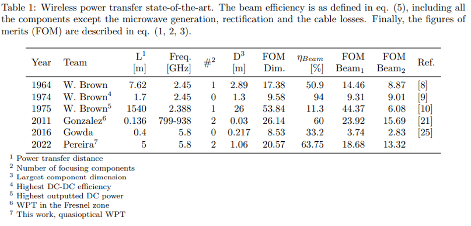
The first wireless power transfer (WPT) experiment was done by Heinrich Hertz, but it was Nikola Tesla who recognized its potential for wirelessly powering devices and actively pursued this goal [1, 2]. To achieve high efficiency wireless power transfer, electromagnetic (EM) radiation can be focused into a beam and directed towards intended targets. This is more easily achieved at higher frequencies, since the system dimensions can be reduced, which only became technologically possible in the 1960s, in great part due to the developments by William Brown in the U.S. [3, 4, 5, 6]. Brown experimented with a wirelessly-powered helicopter [7, 8], developing the rectenna (antenna and rectifying circuit) for it. This enabled two important experiments that still hold WPT records: one for the maximum DC-DC efficiency of 54% [9], and the other for the highest outputted DC power of 30.4 kW for an impressive distance of 1540 m (1 mile) [10]. Naturally, interest in the field prompted WPT projects all around the world, from Europe [11, 12] to Japan [13, 14, 15], among many others. Most dealt with important aspects of microwave generation or rectification, with few explicitly discussing the beam efficiency. This interest arises from WPT’s potential applications, especially where the installation of traditional power supply lines is not feasible or even possible: ground-to-ground WPT to supply power to hard-to-reach locations, ground-to-air for powering airborne platforms for surveillance and communication purposes [16, 17], or even space applications, such as the generation of solar power in outer space to transmit it back down to Earth via microwaves. The latter is widely known as the Solar Power Satellite (SPS) project [18, 19]. However, the beam divergence is still a considerable problem and the difficulty in achieving highly efficient WPT systems has impeded their implementation in real-life situations. Hence, this project aims is to understand and control microwave beams and the way they propagate, for maximizing the beam efficiency, which may then be used in any radiative WPT application. The quasioptical (QO) framework [20] has been used here, which adapts the tools of optics to contexts with high divergence, as is the case of microwaves traveling distances of meters and kilometers. Even though its use is paramount for reducing spillover losses, the implementation of quasioptics in WPT has been mostly theoretical and only seldom have experimental systems been developed. As far as we are aware, no complete WPT system has been analyzed through it. The first system we studied and developed through QO is composed of two sets of a conical horn and parabolic reflector, that were analyzed theoretically using the reciprocity principle. This paper reports the project from theory to complete system experimentation. The experiment most similar to this work consists of a horn-to-horn power transfer system [21], performed at terahertz frequencies, using elliptical mirrors. Maximum beam efficiency of ≈ 60% was obtained for a distance of 13.6 cm at a power of under 8 µW. Although the quasioptics analysis is implemented, the system transfer distance is not related to the components’ parameters, as is here. Finally, the summary in Table 1 includes experimental projects whose beam’s efficiencies are given explicitly or are possible to calculate, to serve as comparison points to this work. As far as we are aware, this study contributes to the state-of-the-art (SOA) in several ways: firstly, new figures of merit are proposed; on the other hand, no QO analysis has been applied to complete WPT systems, relating the gaussian beam’s parameters with the systems components, as is the case here; through it, a high beam efficiency has been achieved, when compared to the SOA. Finally, the QO analysis of this double-reflector system has not been done before, with the obtained results validating the theoretical quantities obtained previously.
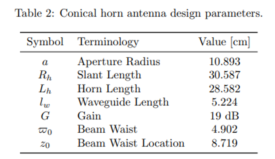
Increasing the beam efficiency through quasioptics
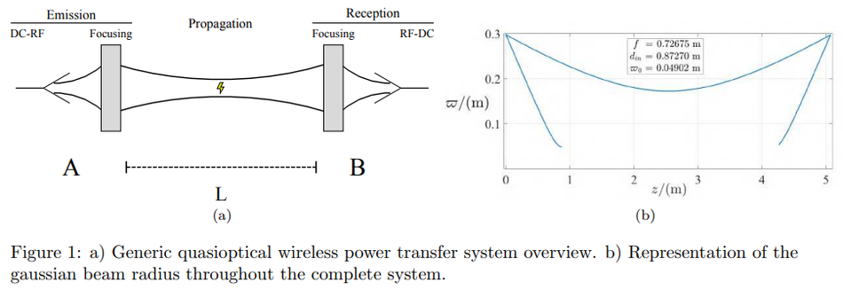
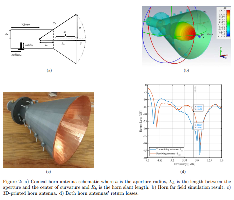
There are two main advantages that QO brings to WPT: this tool is useful for analyzing radiation beams with considerable divergence where the radiation is no longer represented by thin rays but by a beam with a certain gaussian power distribution [20]. How well the antennas generate and receive gaussian beams is accounted for through the coupling efficiency (Eq. 10), which should be optimized for increasing the beam efficiency. On the other hand, QO provides information about the beam radius (Eq. 11) which, if maintained smaller than the system components, effectively reduces the spillover losses. The QO system that was first conceptualized is represented in Fig. 1a. In simple terms, the EM energy is transferred from point A to point B, traversing a distance of L, while using focusing elements for optimizing the beam, controlling its divergence. For simplicity, the reciprocity principle was applied, making the components in A the same as those in B, but in reverse order. This simple concept developed into a double reflector system (Fig. 1b) that was theoretically analyzed [22], whose main results are the relationships between the reflectors’ focal length, f, and the wireless power transfer distance, L (Eq. 13). Following these results, the actual system needed to be defined, after which it was built and subject to experimentation: two horn antennas were designed and manufactured and parabolic reflectors with specific focal lengths were obtained; using only one reflector, the focus location was measured experimentally [23], validating the system for further experimentation. It is important to note that the microwave beam generation and reception were done by a portable network analyzer, hence, these components’ efficiencies are not considered. The main goal was to study the beam transfer and only its efficiency is discussed here, which includes all WPT components except the microwave excitation and reception (Eq. (4) and (5)). The chosen antenna type for generating and receiving the beam were smooth-walled conical horn antenna due to their high coupling efficiency to gaussian beams of 91% (Eq. 10). Their parameters are detailed in Table 2 and schematically represented in Fig. 2a. Although corrugated horns are even better coupled, their increased complexity make them more difficult to manufacture.
Additionally, parabolic reflectors were used, as they were donated for this project. Having defined the system’s fundamental blocks, the components were adjusted for a 5.8 GHz microwave beam propagating a distance of 5 m. The choice of frequency was due to the state-of-the-art, while the distance was considered for being simultaneously feasible and challenging.
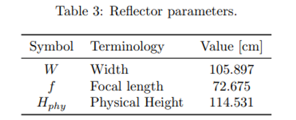
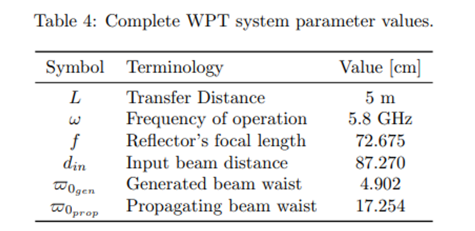
From this starting point, the parameter values that had to be chosen were the generated gaussian beam waist, ϖ0gen , the reflectors’ focal length, f, and the distance between both components, din. Since din is adjustable at any time, the other two parameters were decided iteratively: for a reflector dish with a diameter of 1 m, the necessary gaussian beam would need to have ϖ0 = 4.902 cm; the conical horn antenna final dimensions were determined after following the design principles found in [24] and are detailed in Table 2. After their simulation and optimization using the CST Studio Suite software, they were 3D printed and covered with copper, as can be seen in Figs. 2b and 2c. Following their testing in an anechoic chamber, the S11 parameters (Fig. 2d) were used to calculate the antennas’ gain by the substitution method. Furthermore, after the acquisition of reflectors with acceptable parameters, presented in Table 3, din was adjusted for the intended transfer distance. Hence, the complete system parameter values are described in Table 4.
These were validated in a script from which the schematic of the complete system, represented in Fig. 1b, was obtained. From the theoretical analysis, a preliminary experiment was prepared for measuring the focus location, using only one of the parabolic reflectors. Following its validation, the complete system was set-up and experimented upon. Both the preliminary and the final results used a Keysight FieldFox Microwave Analyzer N9918A connected to the horn antennas by CBL-2M-SMSM+ cables, at a power level of 0 dBm.
The S21 parameters were used as indicators of the beam efficiency. As mentioned previously, the microwave generation and reception losses were not accounted for since the network analyzer was used. Similarly, the cables’ losses were discarded due to the calibration performed everyday before the experiments took place. Therefore, the S21 results provide information regarding the horn antennas’ and parabolic reflectors’ efficiency and, most importantly, the microwave beam collection efficiency throughout the system. Finally, a calculation of the estimated efficiency was done: the horn antennas were designed in CST Studio Suite and an efficiency over 98% was provided by the software. Since no practical measurements were done on the antennas’ efficiency, this value was used in the calculation. The reflectors’ efficiency was provided by the manufacturer as being 74%. Due to the system’s design always keeping the beam radius smaller than the components’ aperture, the spillover losses are negligible. Considering all this information, the maximum expected beam efficiency was ηBeamest. = 0.982 × 0.742 = 52.6%.
5-meter wireless power transfer
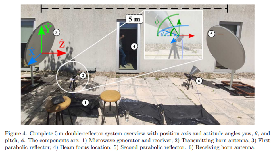
A preliminary analysis was performed to verify that the radiation focus location was indeed at the expected distance from the reflector of L/2 = 2.5 m [23]. This measurement consisted of measuring the S21 parameters of both the horn antennas, while one served as the reflector’s feed and the other was used to sweep the distance from the reflector, at a height of 1 meter. The maximum power received on this preliminary experiment was -12.537 dBm at a distance of 245 cm from the reflector, a value close to the theoretical one of 250 cm. The main reasons for the displacement are attributed to possible system misalignments or to a difference in the gaussian beam parameter of the generated antenna. Either way, these are minimum and were accounted for in the complete system experiment. These preliminary results validated the theoretical analysis, prompting the complete system set-up for the 5 m WPT experiment. Due to the size of the complete system, the experiments had to take place on the outside patio of the lab facilities, as can be seen in Fig. 4. In this figure, all the systems’ components are presented, as well as the axis of reference. Following the power flow, the components are the microwave generator and receiver (1), the transmitting horn antenna (2), the first parabolic reflector, responsible for focusing the beam at 2.5 m (3), the beam focus location (4), the second reflector, responsible for transforming the beam for optimal reception (4) and finally the receiving horn antenna (5). With these components, two different sets of measurements were conducted: the first consisted in discovering the optimal parameter values and measuring the efficiency value for 15 minutes, while the latter consisted of a thorough parameter variation for observing their effect on the overall WPT efficiency. Starting from the theoretically optimal values, various parameters were adjusted in order to arrive at the maximum WPT efficiency. The complete parameters to be optimized were both the horn antennas’ position and attitude and the parabolic reflectors’ attitude. Each of these is a product of multiple components, totalling in 14 parameters to explore: each antenna had three positioning axis, xyz, and two angles, yaw (θ) and pitch (ϕ); the reflector’s parameters possible of adjustment were only its attitude angles, elevation and horizontal sweep. These parameters are visibly explained in Fig. 4.
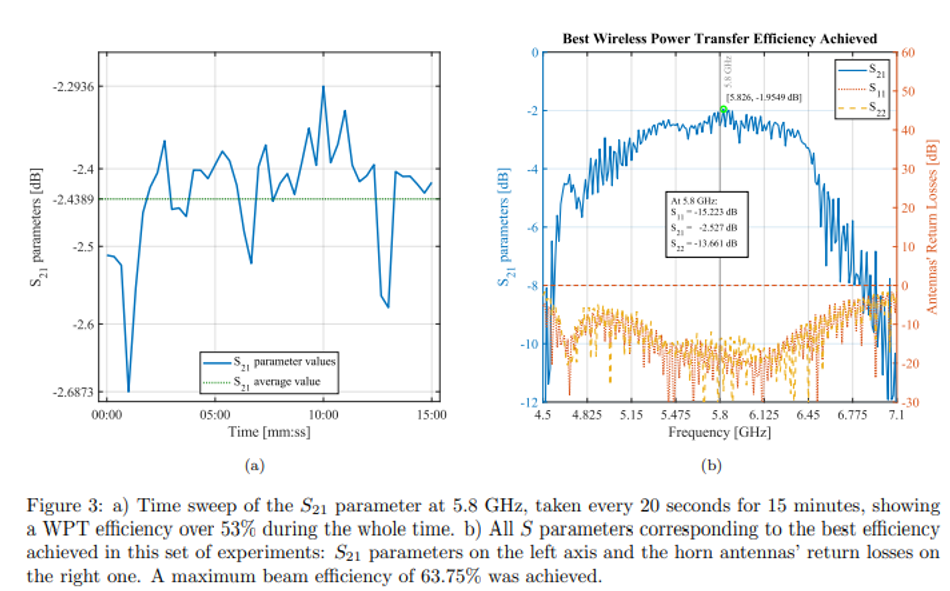
The horn antenna’s rolling angle was not varied since it is related to the their linear polarization. Therefore, the best case was when their roll angle was the same or at a 180 degree rotation. Finally, a 15 minutes experiment was conducted at the optimal point, with measurements being taken every 20 seconds. In this manner, it was possible to achieve a power transfer efficiency over 53%, as seen in Fig. 3a. The total 45 points averaged at −2.4389 dB (57.0%) for which one can conclude that 0.513 J were transferred during this time. The following conclusions were made possible: although the measurements were taken in an outdoors location, the wind effects were usually not significant. However, on rare occasions with stronger wind intensity, the systems’ components were redirected to the point where a difference in the beam efficiency was noted. Nevertheless, when the intensity reduced again, the efficiency would return to the previous nominal values, indicating that the components’ fixation mechanism was not perfect but suitable for the experiment. Frequently, this phenomenon turned out to be advantageous because efficiency values better than thought to be achievable with the current system would be measured, prompting further alignment efforts.
System sensitivity
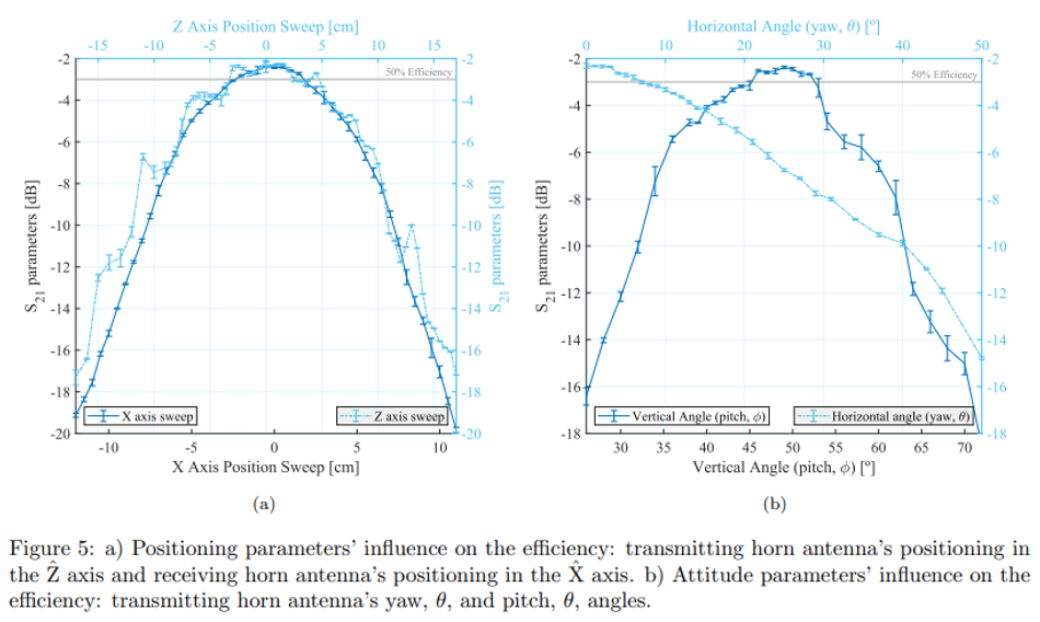
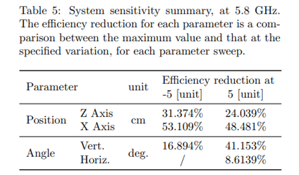
The other set of measurements consisted in observing how the beam transfer efficiency varied with the different parameters and quantify the system’s sensitivity. Therefore, from the optimal point obtained previously, a thorough variation of the most important variables was performed. Attentively, in order to reduce the wind’s impact in the measurements, the following results were manually repeated five times for each configuration, with the average being taken as the most indicative value. The parameters that were varied in this analysis were the transmitting horn antenna’s positioning in the Z axis and the receiving horn antenna’s position- ˆ ing in the X axis, whose results are summarized in ˆ Fig. 5a, as well as the transmitting antenna’s yaw, θ, and pitch, θ, angles, present in Fig. 5b. From them, it is possible to conclude that the system is highly sensitive, with the vertical angle being the most sensitive of all parameters. These results are important for setting up future experiments: the components’ attitude must be explored first, since they are more impactful in the overall system alignment. It is also possible to observe that the received gaussian beam’s waist can be determined from the X axis ˆ variation. Its electric power distribution falls to 1/e at around −6 and 5.5 cm, hence, the beam waist can be calculated as 5.75 cm using this method, approximate to the theoretical value of 4.90 cm. Finally, this thorough parameter variation enabled the measurement of the best wireless power transfer efficiency achieved, verified to be 63.75 %, as is visible in Fig. 3b. Figure-of-merit relating physical dimensions Aiming to compare our results with the SOA, but lacking to find a figure-of-merit (FOM) in the literature, we propose a new one. The goal is to facilitate the comparison between WPT projects in terms of the systems’ physical dimensions, by giving a fast and easy quantity, relating the power transfer distance (L) with the systems’ components largest dimension (D), the number of components (n), and the wavelength λ. This dimensional figure-of-merit, F OMDim., was defined as:

This definition is generalized so that it can be applied even in WPT projects that do not use the quasioptics analysis. The transmitting and receiving antennas are not included in n, since they are fundamental components. Additionally, in order to have a single figure-ofmerit capable of giving an overall idea of the beam part of any WPT system, we also propose the following quantities that include the beam efficiency, ηBeam, as defined in Eq. (5):
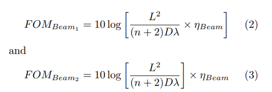
where the only difference between them is whether the beam efficiency is included in the logarithmic function or not. By having it separately, (Eq. (3), more weight is given to the beam efficiency. All of these are applied to the state-of-the-art and compared in Table 1, where the system with the highest dimensional FOM is the work by Brown that transferred power through 1540 km [9]. Our solution is in third place, behind Brown’s and the work of Gonzalez [25], which for the high frequency of operation achieved a relatively high distance of power transfer, although it is only 13.6 cm. On the other hand, for the 2nd FOM that includes the beam efficiency, the one where it is more impactful, eq. (3), our work ranks highest for long-range applications, having achieved a high beam efficiency when considering the system components and power transfer distance. This discussion will be further analyzed, serving as a starting point for a wireless power transfer figure of-merit.
Discussion
The experimental results enabled the measurement of a beam efficiency higher than initially estimated. We believe this is due to the reflectors having a higher efficiency than provided by the manufacturers. Although the case can be made that this increase is due to reflections by the floor and walls, the high directivity of the beam discredits this possibility. The beam was intentionally blocked in multiple locations between both reflectors and its efficiency drop was only noticed in the central axis, as expected, meaning that the beam’s side lobes and ground or wall reflections are negligible. Hence, a review of each components’ efficiency and their comparison with the estimated values are shown in Table 6.
In order to better quantify the system, the complete distance that the beam propagates is L + 2 × din = 5 + 2 × 0.87270 = 6.745 m. On the other hand, from a traditional antenna theory point of view, the transmitting and receiving blocks, each composed of a horn and a reflector, have a height of 1.306 m. All of this for a wavelength of 0.0517 m, which means that the distance between the reflectors is ≈ 97λ When comparing with the state-of-the-art in Table 1, the advantages of using quasioptics for WPT become clear: the spillover losses are negligible making this system the best beam efficiency ever designed for WPT, surpassing the previous works when taking into consideration the number of focusing components and transfer distance. However, this system can be improved: the reflectors used were commercially available for telecommunication purposes, hence, the beam efficiency can be further improved by developing higher efficiency focusing elements. Additionally, the beam efficiency can be increased by using corrugated horns instead of the smooth-walled horns that were used since these antennas have a higher gaussian beam coupling.
Conclusions
A complete 5 meter double-reflector system was experimented upon with the goal of achieving the highest wireless power transfer efficiency possible at 5.8 GHz, validating the theoretical analysis performed previously using quasioptics. From this experiment, an efficiency of 63.75% was obtained, showing that a microwave beam was successfully optimized for the system in question, enabling the significant reduction of spillover losses, to the point of them being negligible. The major losses were attributed to the parabolic reflectors used, showing that the development of higher efficiency focusing components is an important part of the future of wireless power transfer. This is because the losses added by the focusing components for controlling the beam’s divergence, are offset by a reduction in the spillover losses, enabling an overall increase in beam efficiency. Furthermore, the dependence of the beam transfer efficiency with different system parameters has been discussed, as well as the wind’s impact on the experiment. The receiving gaussian beam waist was also measured to be 5.75 cm. On the other hand, several figures-of-merit have been proposed, aiming to compare various WPT systems with the power transfer distance and beam efficiency, advancing the state-of-the-art in WPT analysis. Following this work, the same double-reflector system can be used for further validating the quasioptical usage in WPT systems. The system can be optimized for longer distances by adjusting some system parameters. On the other hand, the eventual usage of a rectenna for receiving power should reduce the system’s sensitivity, albeit with a possible loss in the receiving antenna efficiency. Finally, the power generation can also be implemented so that a complete WPT efficiency can be measured. On a final note, although the principles of quasioptics have been developed for some decades, these have been mostly applied for microwave astronomy and to study materials. The development of a complete system with low spillover losses for wireless power transfer has not been proposed until now, nor experimented upon. These positive results obtained here are evidence that the quasioptical framework is advantageous for developing radiative wireless power transfer systems with high efficiency.
Read the research paper here: Quasioptics for Increasing the Beam Eciency of Wireless Power Transfer Systems
References
[1] A. S. Marincic, “Nikola tesla and the wireless transmission of energy,” IEEE Transactions on Power Apparatus and Systems, vol. PAS-101, no. 10, pp. 4064–4068, 1982.
[2] W. Lumpkins, “Nikola tesla’s dream realized: Wireless power energy harvesting.” IEEE Consumer Electronics Magazine, vol. 3, no. 1, pp. 39–42, 2014.
[3] W. C. Brown, “The history of power transmission by radio waves,” IEEE Transactions on Microwave Theory and Techniques, vol. 32, no. 9, pp. 1230–1242, 1984.
[4] ——, “The history of wireless power transmission,” Solar Energy, vol. 56, no. 1, pp. 3–21, 1996, wireless Power Transmission. [Online]. Available: https://www.sciencedirect.com/science/article/pii/ 0038092X9500080B
[5] R. M. Dickinson, “Wireless power transmission technology state of the art the first bill brown lecture,” Acta Astronautica, vol. 53, no. 4, pp. 561–570, 2003, the New Face of Space Selected Proceedings of the 53rd International Astronautical Federation Congress. [Online]. Available: https://www.sciencedirect.com/science/ article/pii/S0094576503800176
[6] C. T. Rodenbeck, P. I. Jaffe, B. H. Strassner II, P. E. Hausgen, J. O. McSpadden, H. Kazemi, N. Shinohara, B. B. Tierney, C. B. DePuma, and A. P. Self, “Microwave and millimeter wave power beaming,” IEEE Journal of Microwaves, vol. 1, no. 1, pp. 229–259, 2021.
[7] W. Brown, “Experimental airborne microwave supported platform,” Raytheon Company, Raytheon Co. Burlington Ma. Spencer Lab., Tech. Rep. DA-64-14, 1965.
[8] ——, “Experiments in the transportation of energy by microwave beam,” in 1958 IRE International Convention Record, vol. 12, 1964, pp. 8–17.
[9] R. M. Dickinson and W. Brown, “Radiated microwave power transmission system efficiency measurements,” Jet Propulsion Laboratory, California Institute of Technology, Pasadena, Tech. Rep. 33-727, 1975.
[10] R. M. Dickinson, “Evaluation of a microwave high-power reception-conversion array for wireless power transmission,” Jet Propulsion Laboratory, California Institute of Technology, Pasadena, Tech. Rep. 33-741, 1975.
[11] N. Borges Carvalho, A. Georgiadis, A. Costanzo, H. Rogier, A. Collado, J. A. Garc´ıa, S. Lucyszyn, P. Mezzanotte, J. Kracek, D. Masotti, A. J. S. Boaventura, M. de las Nieves Ru´ız Lavin, M. Pi˜nuela, D. C. Yates, P. D. Mitcheson, M. Mazanek, and V. Pankrac, “Wireless power transmission: R&d activities within europe,” IEEE Transactions on Microwave Theory and Techniques, vol. 62, no. 4, pp. 1031–1045, 2014.
[12] C. A. I. Team, “Europe and the future for wpt : European contributions to wireless power transfer technology,” IEEE Microwave Magazine, vol. 18, no. 4, pp. 56– 87, 2017. 10
[13] N. Shinohara, “History of research and development of beam wireless power transfer,” in 2018 IEEE Wireless Power Transfer Conference (WPTC), 2018, pp. 1–4.
[14] ——, “History and innovation of wireless power transfer via microwaves,” IEEE Journal of Microwaves, vol. 1, no. 1, pp. 218–228, 2021.
[15] H. Matsumoto, “Research on solar power satellites and microwave power transmission in japan,” IEEE Microwave Magazine, vol. 3, no. 4, pp. 36–45, 2002.
[16] J. Schlesak, A. Alden, and T. Ohno, “A microwave powered high altitude platform,” in 1988., IEEE MTT-S International Microwave Symposium Digest, 1988, pp. 283– 286 vol.1.
[17] K. D. Song, J. Kim, J. W. Kim, Y. Park, J. J. Ely, H. J. Kim, and S. H. Choi, “Preliminary operational aspects of microwave-powered airship drone,” International Journal of Micro Air Vehicles, vol. 11, p. 1756829319861368, 2019. [Online]. Available: https: //doi.org/10.1177/1756829319861368
[18] P. Glaser, “Power from the sun: its future.” Science, vol. 162 3856, pp. 857–61, 1968.
[19] J. McSpadden and J. Mankins, “Space solar power programs and microwave wireless power transmission technology,” IEEE Microwave Magazine, vol. 3, no. 4, pp. 46–57, 2002.
[20] P. F. Goldsmith, Quasioptical Systems: Gaussian Beam Quasioptical Propagation and Applications. Piscataway, NJ,: IEEE Press, 1998.
[21] A. Gonzalez, Y. Uzawa, Y. Fujii, K. Kaneko, and K. Kuroiwa, “A horn-to-horn power transmission system at terahertz frequencies,” IEEE Transactions on Terahertz Science and Technology, vol. 1, no. 2, pp. 416–424, 2011.
[22] R. A. M. Pereira, N. B. Carvalho, and J. P. da Cunha, “Quasi-optical analysis of a double reflector microwave antenna system,” Wireless Power Transfer, vol. 5, no. 2, p. 75–86, 2018.
[23] R. A. M. Pereira, N. B. Carvalho, and A. Georgiadis, “Focus location measurement of a quasioptical double reflector system,” in 2021 IEEE Wireless Power Transfer Conference (WPTC), 2021, pp. 1–4.
[24] Y. T. Lo and S. W. Lee, Antenna Handbook: Volume II Antenna Theory. New York, NY: Van Nostrand Reinhold, 1993.
[25] V. R. Gowda, O. Yurduseven, G. Lipworth, T. Zupan, M. S. Reynolds, and D. R. Smith, “Wireless power transfer in the radiative near field,” IEEE Antennas and Wireless Propagation Letters, vol. 15, pp. 1865–1868, 2016.
[26] Q. Chen, X. Chen, and X. Duan, “Investigation on beam collection efficiency in microwave wireless power transmission,” Journal of Electromagnetic Waves and Applications, vol. 32, no. 9, pp. 1136–1151, 2018. [Online]. Available: https://doi.org/10.1080/09205071. 2018.1425158
[27] Y. Karandikar, “Factorization of gaussian coupling efficiency and algorithm to compute it,” in 2012 6th European Conference on Antennas and Propagation (EUCAP), 2012, pp. 868–872.
About the University Technology Exposure Program 2022
Wevolver, in partnership with Mouser Electronics and Ansys, is excited to announce the launch of the University Technology Exposure Program 2022. The program aims to recognize and reward innovation from engineering students and researchers across the globe. Learn more about the program here.
