Functional Fluids: Designing an Ink Delivery System for Recirculating Piezo Printheads
In this article, we will discuss the different aspects of an effective ink delivery system. We will focus on a recirculating inkjet system as they are highly in demand in industry, especially where functional fluids come into play.
04 Jan, 2024. 8 minutes read
Ink Delivery System for Recirculating Piezo Printheads
This article was first published on
www.techblick.comBy Mikael Boedler, INKATRONIC GmbH | mb@inkatronic.com
Niederdorfstrasse 6, 4063 Hörsching Tel.: +43 7221 22298
In this article, we will discuss the different aspects of an effective ink delivery system. We will focus on a recirculating inkjet system as they are highly in demand in industry, especially where functional fluids come into play.
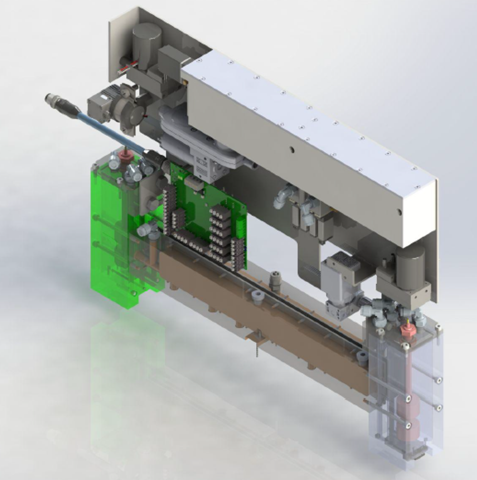
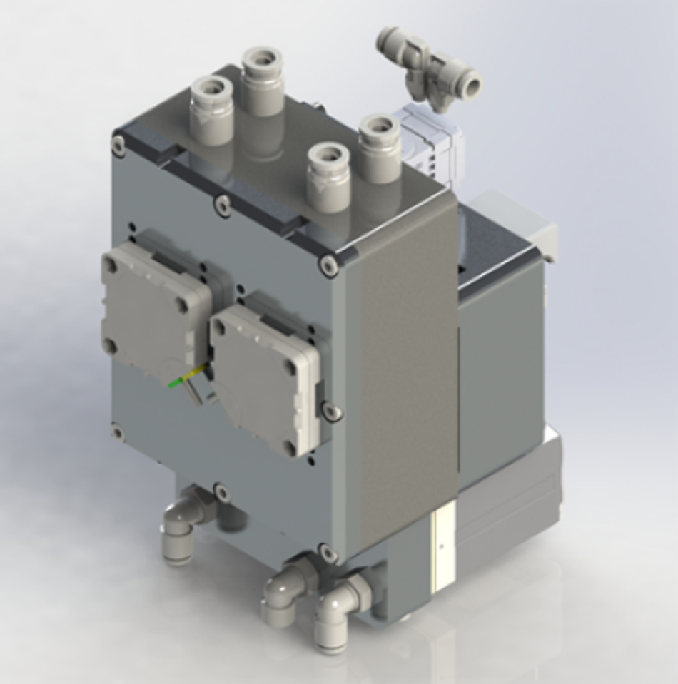
Though recirculating printheads are mostly on the same price level as non-recirculating, gravity feed equivalents the ink supply system needed is much more intricate and as a result, significantly more challenging to implement (an example of a recirculating ink delivery system is shown in figure 1 below). The benefits of recirculating systems, however, are clearly outlined in the next section making it a worthy endeavour.
Advantages of Recirculating Inkjet Technology in Industry
Improved Print Quality - Recirculating printheads maintain a consistent ink temperature and viscosity, resulting in more consistent droplet formation when jetting at various frequencies. This leads to a better print quality with sharper details and better lay-down accuracy.
Reduced Nozzle failures - Continuous ink circulation helps prevent nozzle failures caused by ingesting air, ink drying out, or ink settling, ensuring uninterrupted printing.
Faster Start-Up Times - most recirculating printheads can start printing immediately, whereas gravity-fed printheads may require cleaning cycles to recover missing nozzles.
Enhanced Printhead Longevity - The reduced risk of nozzle clogs and more stable operating conditions can extend the lifespan of recirculating printheads when compared to gravity feed systems.
Improved Jetting Consistency - The stability in ink properties provided by recirculating printheads helps maintain consistent output across multiple print jobs, making them suitable for high-volume and continuous printing applications.
Reduced Maintenance - Gravity feed printheads may require more frequent cleaning, purging, and maintenance, while recirculating printheads need less attention, leading to lower downtime and operating costs.

Basic Principles of a Recirculating Ink Delivery System
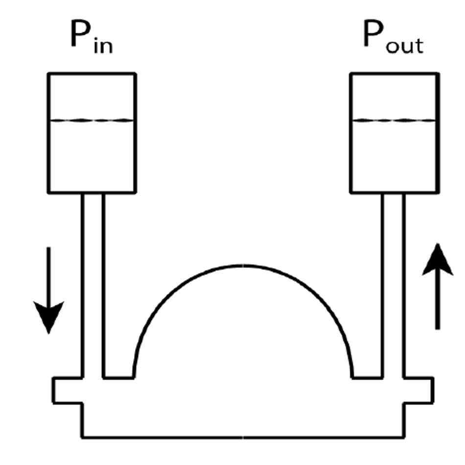
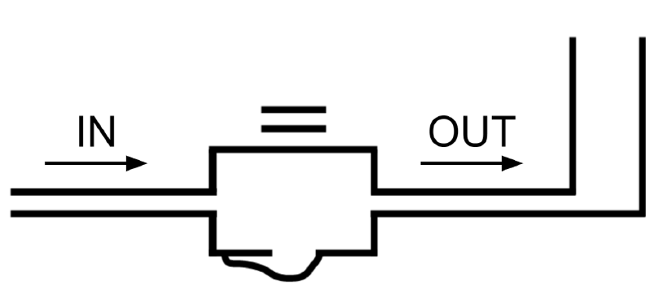
In theory, a recirculating ink supply is simple. By creating a pressure difference between the “in” and “out” ports of a printhead a flow of ink is generated (see Figure 2). At the same time, the correct pressure difference must be maintained to generate a slightly negative meniscus pressure at the nozzles.
Achieving such a state initially is relatively easy, the hard part is maintaining it while the printhead starts jetting, recirculating pumps run and ink is refilled to compensate for the rate of ink leaving the system.
What are the Requirements for a Recirculating Ink Delivery System
Pressure Control
A meniscus pressure operating window is around ±2 mbar. Though changes within this range are unlikely to affect jetting stability, drop properties will always be affected by the smallest changes causing shifts in printed densities. For this reason, keeping the meniscus pressure within an optimal range is essential.
Ink Pumps
A reliable ink pump is essential for circulating ink through the system. Diaphragm pumps are commonly used for inkjet applications due to their accuracy and low maintenance requirements, though they must offer good speed control. Sharp start/stop operations are undesired and low pulsation is essential.
Peristaltic pumps have their advantages but they need more frequent maintenance with their tubes, while gear pumps should be avoided due to their high shear rates which can affect an ink’s properties in circulating loops.
For good chemical resistance, in the case of diaphragm pumps, they should contain FFKM valves and seals. Teflon is the recommended material for membranes.
Valves
As a general rule, valves should be avoided where possible. If needed they have to be compact, with FFKM elastomers, large orifices, and low power consumption. This combination is often not available as standard and a partnership with a manufacturer is required to develop such valves.
Pressure Spikes
Pumps and valves create varying pulses of pressure, each of them, or in combination, can lead to undesired spikes in pressure. Pressure spikes can cause an immediate loss of nozzles.
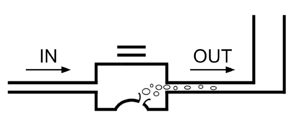
A positive spike can float a nozzle causing nozzle plate wetting (as shown in figure 3) and a cleaning stop. A negative pressure spike can lead to nozzle drop-outs by the ingestion of air (as shown in figure 4). In the case of a momentary ingestion of air, this is less consequential as the circulating flow of ink will quickly recover the nozzles.
An acceptable range for pressure spikes can be +5 to -10 mbar, noting that the “in” pressure is most sensitive to this.
It should also be noted that in some cases when large amounts of nozzles are started/stopped simultaneously they themselves can cause pressure spikes at the inlet side of the printhead.
Tubing and Connectors
Appropriate fittings and tubing should be used that are compatible with the inks chosen for the printing application. Long-term testing should be conducted to observe shrinking, swelling, and sweating. All tubes should be kept as short as possible and with multiple heads they have to be exactly equal in the length.
High-quality connectors are recommended as a leaking inkjet system can cause lots of trouble to fix, not to mention the mess. More critical though, is the ingestion of air at any point of the negative pressure side of the system, such a leak is almost impossible to identify. This causes Ink foaming which provokes large jetting dropouts and the level control system to give false readings, which can cause an ink overflow.
Materials for Manifolds and Tanks
The material chosen for an ink tank should be compatible with the ink chemistry, preventing any chemical reactions or contamination. Common materials for ink tanks are stainless steel, high-density polyethylene (HDPE), polypropylene (PP) and aluminium. In the case of aluminium, it should never be used with water-based inks.
Sedimentation and Draining of the system
Sedimentation can occur in only a few hours which leads to unstable jetting and nozzle clogging. To avoid sedimentation of high-density inks they need constant motion or stirring. Ink should be kept circulating through the entire ink supply system and extended idle times should be avoided. For a weekend shutdown, it is recommended to implement an automatic draining process to remove the ink from the system and keep it agitated in the main ink reservoir.
Temperature Control
Ink temperature should be maintained precisely at the optimal value, deviating only ±1°C. This has to be controlled at the tanks and at each printhead. The tank heaters have to be well distributed, local overheating of ink must be avoided. Flow-through heaters in the ink recirculation lines can be used in addition, if needed.
Experiments have to be conducted in order to determine an ink’s sensitivity to temperature.
Printheads with integrated heaters should reach the target ink temperature with the heater switched off, otherwise the temperature reading by the head thermistor may not be representative of the ink temperature at the “in” and “out” ports. Printhead heaters should be used for fine-tuning the ink temperature, raising it by not more than 2°C.
Degassing, Air Bubble Removal
Ink formulations can contain dissolved gases or air bubbles, which can disrupt the flow of a fluid within the printhead. A degasser removes these entrapped gases from the ink, resulting in more stable and reliable jetting.
This is especially recommended for water-based inks, while UV and solvent-based inks will always show improvements from this.
The Parameters for Setting up an Inkjet System
For each specific ink and printhead, a different set of parameters will need to be determined. These parameters include:
- Temperature.
- “In” and “out” pressures.
- Flow rate.
- Head voltage.
- Waveform.
These parameters must be determined experimentally by setting up an ink supply system, with a chosen printhead, the printhead electronics and the ink of choice.
When testing a new ink the starting point should be to set the recommended temperature/viscosity set-points provided by the ink manufacturer in accordance with the printhead requirements. With the right temperature settings the “in” and “out” pressures are set in the range which prevents the printhead from dripping or sucking in air. The resulting flow rates are in a range of 10 to 200 ml/min depending on the printhead and have to be measured and maintained.
At this point, the jetting performance can be analysed using a dropwatcher.
The “in”/”out” pressures can now be adjusted with each jetting trial to find the region within which we achieve the best jetting performance. A flow rate that becomes too low can cause jetting instability and a delay/complete loss of nozzle recovery. A flow rate that is too high can affect the jetting straightness.
The next parameter to test is the temperature. Temperature changes during the operation of a system should not fluctuate more than ±1°C. Any changes in temperature during jetting can affect drop size, jetting speed,as and jetting stability. As with pressure, temperature should be adjusted between jetting tests under the dropwatcher in increments of 0.5°C, while keeping other parameters constant. This should also produce a profile showing the ideal range in jetting performance, this time, relative to temperature.
If the ideal temperature is different to the temperature set at the start of the procedure, the pressure range test can be repeated to see if the optimal pressure range changes with the new temperature value. Both pressure and temperature range tests would need to be repeated until the optimal pressure and temperature ranges stay constant.
This entire procedure has to be repeated for each different ink chemistry, though it is a more complex procedure to swap out a printhead to test with the same ink. It is recommended to select as few printheads as early as possible in the development stages of a printing solution to avoid uneconomically lengthy development times.
Functional fluids often have a high amount of solids in their chemistry and as such require frequent/constant agitation to prevent sedimentation, mentioned earlier. For chemists, it’s a challenge to design such fluids within the low viscosity requirements of piezo printheads, somewhere between 4 to 20 mPa s. Testing is recommended to avoid unpleasant surprises in the form of damaged printheads.
Other parameters such as head voltage and waveform can also be analysed, however, they are outside of the scope of this article.
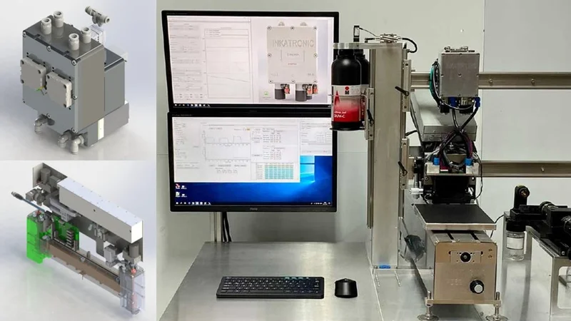
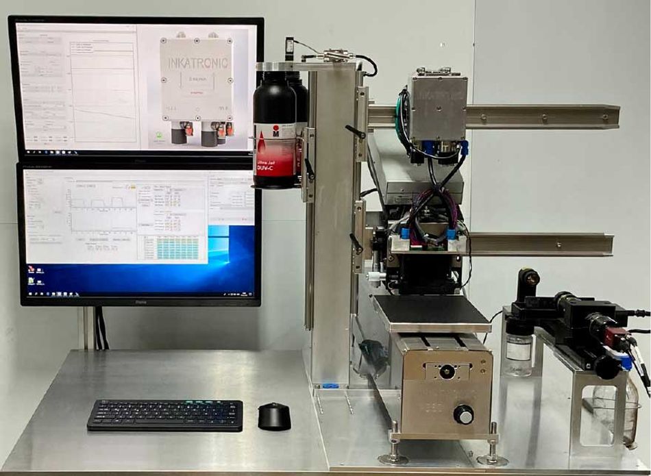
A dedicated apparatus for complex inkjet development is the INKATRONIC Test Bench, with Dropwatcher shown in Figure, 6 below. With such equipment it is possible to gain productivity and have all the necessary tools at your side to effectively achieve your targets.
Join us at TechBlick's Future of Electronics RESHAPED conference & tradeshow in Berlin on 17-18 OCT 2023 - www.techblick.com/electronicsreshaped. For your special attendee discounts please contact us at mb@inkatronic.com.