Developing A Scalable Hyperloop
Taking a dive into the future of transportation

Each year, people tend to travel further and further. For all modes of fast transportation problems will arise in the near future. The capacity of existing infrastructure does not suffice for the growing demand, leading to large waiting queues and traffic jams. Additionally, current modes of transportation are energy inefficient and large contributors to rising carbon dioxide levels and climate change. Furthermore, current modes of transportation are sensitive to external influences, leading to disruptive situations.
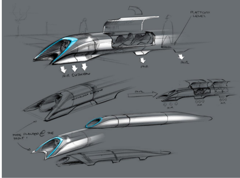
A promising solution for these problems is the hyperloop: a high-speed transportation system using near- vacuum tubes in which pressurized vehicles travel. The concept of hyperloop was initiated back in 1799 as an atmospheric railway by George Medhurst and got reintroduced by the publication of the white paper of Elon Musk in 2013 (Figure 1). By reducing the air resistance and rolling resistance, a hyperloop could travel efficiently with speeds over 1000 kilometers per hour. The enclosed environment of the system ensures reduced external influences.
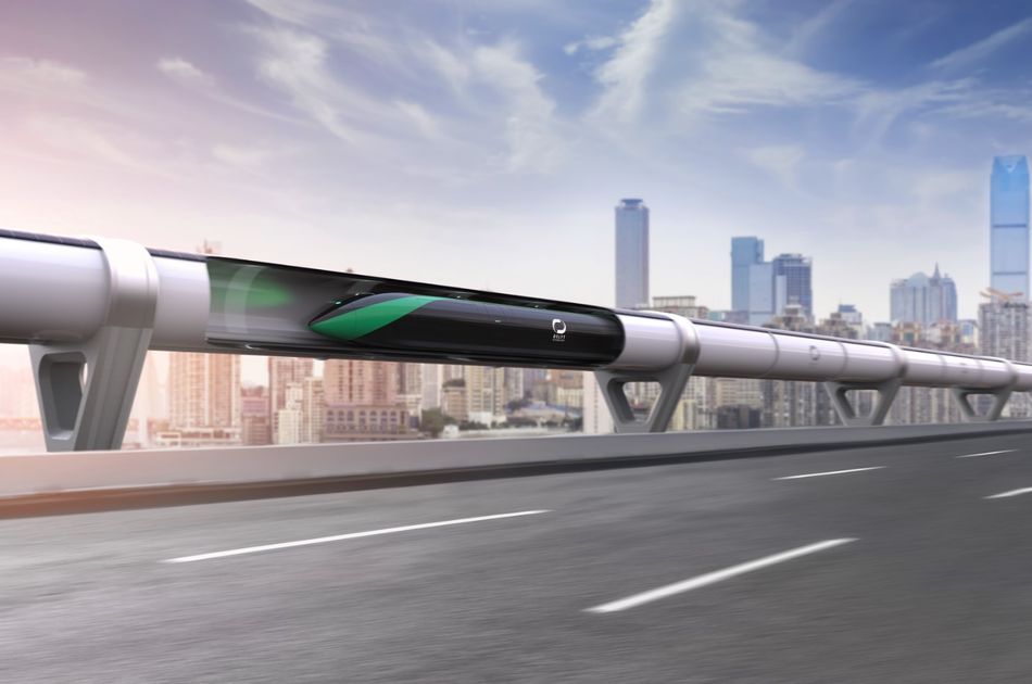
The hyperloop system is designed to replace continental flights. In short, it is a pod which is moving through a vacuum tube from A to B. The pod levitates in the tube using magnetic levitation. Furthermore, the pod moves by the use of magnetic propulsion. Because of the vacuum and levitation, the pod is not exposed to air resistance and rolling resistance respectively. This results in a highly efficient energy use and speeds around 1000 kilometers per hour. The hyperloop can be seen in Figure 2.
The design objective
Delft Hyperloop has the goal to make a fully scalable hyperloop system, to show that the hyperloop can be realized in the near future. For a hyperloop system to be scalable, it needs to have a propulsion method which is efficient for long distance travel. Furthermore, the infrastructure, station design and safety aspects need to be included in the design.
To achieve this goal, we took the first steps designing, producing, testing and operating a scalable hyperloop pod, incorporating the eventual hyperloop propulsion method: the Linear Synchronous Motor (LSM) system. Our hyperloop pod is not yet designed to levitate. This will be a next step in the process.
In Figure 3, you can see our system overview. Here you can see all the subsystems, which together create our hyperloop system. To ensure a scalable design, the system consists of a pod and a compatible track-design as one of its key features.
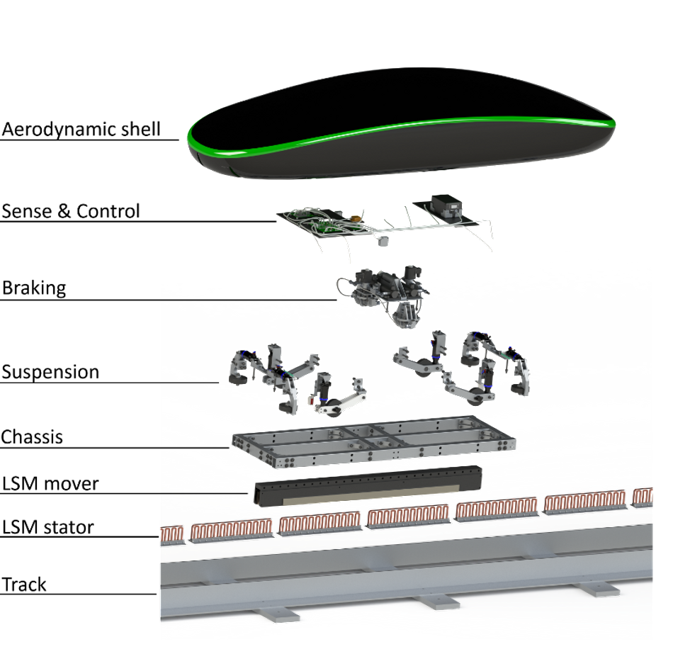
The design can be divided into five subsystems which come together, allowing the system to operate in harmony. The subsystems are: propulsion, sense & control, structures, braking, and suspension. In addition, we have a scalability department who focus on the infrastructure and implementation of the hyperloop in the real world. Since we want to explain the scalable aspects of our hyperloop system, we will focus on propulsion and scalability in this article.
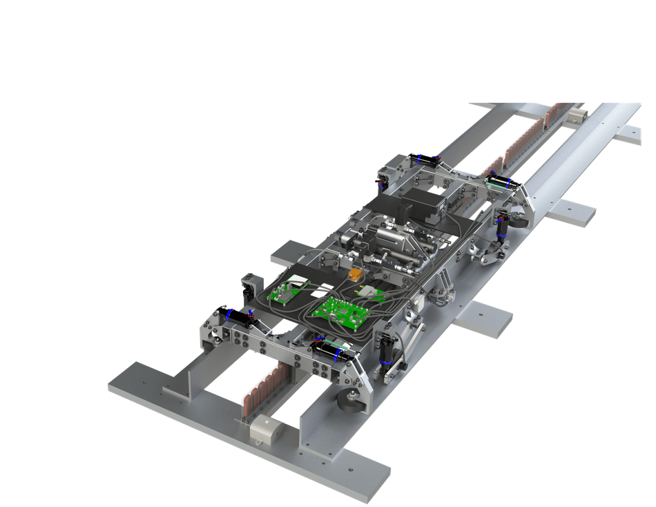
The pod is designed to run on the Delft Hyperloop track on which it can perform symmetric trajectories. It can propel itself, come to a halt and reverse again. The system is shown in Figure 4.
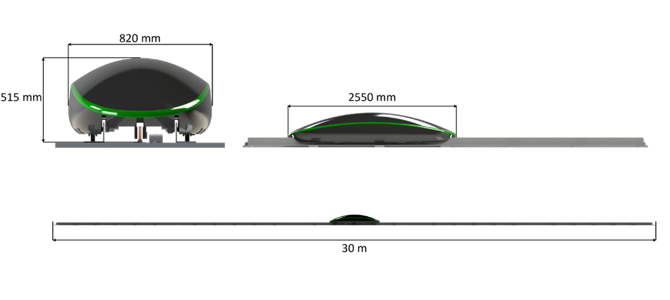
Top level specifications
As an introduction to the explanation of the subsystems, Figure 5 shows the top-level dimensions of the Pod and the Track. The system is designed to operate at a pressure of 100 mbar, travel bi-directionally and handle speeds of up to 200 km/h. After this speed, it is assumed the (eventual) hyperloop will levitate and irregularities in the track will not affect the system anymore [Cho et al, 2009].
Propulsion
The hyperloop propulsion system is there to accelerate the pod to cruising speed and maintain this speed. The propulsion method which we chose is called a Linear Synchronous Motor (LSM), which uses magnetic propulsion. This method is the most efficient way of propelling a levitating pod.
The LSM has high efficiency and speed compared to other propulsion systems. One reason for this is that the battery for the propulsion system is not located in the pod but in the track. This reduces the weight of the pod significantly. In addition, the LSM does not have to induce a magnetic field in the track, which would give major efficiency losses. Finally, LSM system could be used for regenerative braking, in order to regain energy. These aspects make the LSM the most scalable solution.
The LSM consists of a permanent magnet and coils. For our scalable design we chose to put the permanent magnet in the pod and the coils in the track. The coils (1), which are arranged in a series array can be seen between the L-beams in Figure 6. The permanent magnets (2) surround the coils on the track.
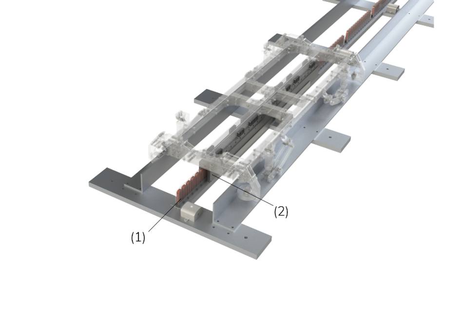
The permanent magnets in the pod provide a stationary magnetic field, while the coils in the track provide a varying magnetic field. The coils interacting with the magnets produce a thrust force through the repelling or attracting force between equal or opposing magnetic poles respectively. By running a 3-phase alternating current through the set of coils, a varying magnetic field is generated with alternating poles, which can be controlled in strength and speed of change by varying the magnitude and frequency of the provided current.
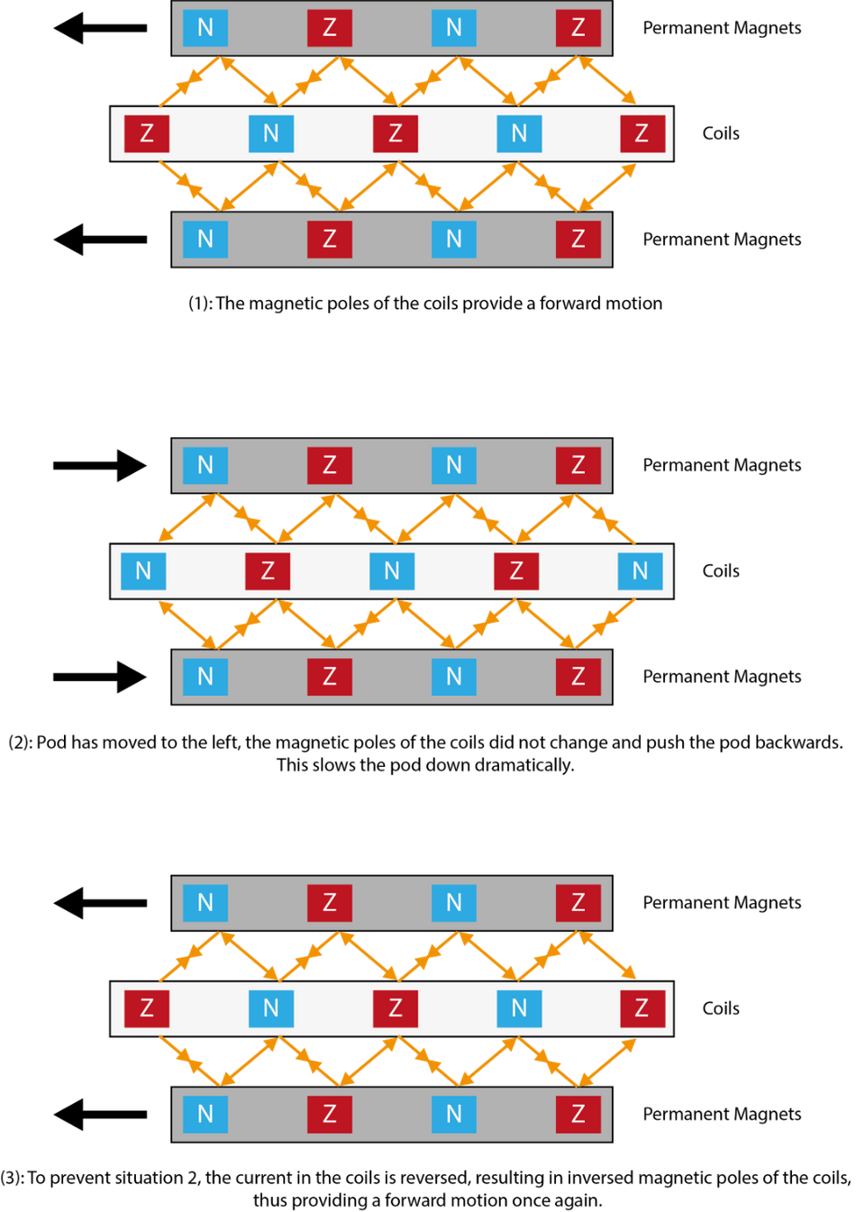
In Figure 7, the principle can be seen at a certain time, where the thrust forces between the magnets and the coils are indicated with arrows, thus propelling the pod in the left direction (1). If nothing changes, and the pod propels in the left direction, the magnets and coils will start to work against the pod, pushing it back (2). In order to prevent this situation and keep the forward force on the pod, the current will be reversed hence reversing the magnetic poles in the coils (3). This will result in a forward force once again. By alternating the current at the right time instances, the pod will be accelerated to the desired speed.
Scalability
Besides producing a hyperloop pod, we also focus on working out challenges that the general hyperloop concept faces. These challenges include technical aspects like construction of infrastructure, tube material and energy consumption, but also financial and political aspects like investors, role of government and placement of the hyperloop station. Works out these challenges through research projects with partners and designing parts of the hyperloop system through our own vision.
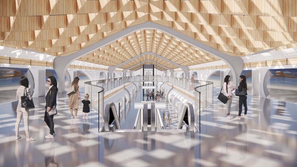
An example is the placement and design of a hyperloop station in the Netherlands. One of the major advantages of hyperloop as a mode of fast transportation over aviation is the potential for a station that is closer to the city center. Where airports are often located far outside of the city, the hyperloop passenger could walk through the station doors right into the city. We therefore envision the main hyperloop station in the Netherlands to be on top of the Amsterdam Zuid train station. Placing the station here integrates the hyperloop perfectly into existing modes of public transportation, such as trains, trams and busses. Amsterdam’s business hub is right outside the station’s doors, while the city center is just at 15-minute metro ride away.
Figure 8 Shows a part of how we envision the Amsterdam hyperloop station. The station is designed with efficiency in mind. A passenger needs to be able to move from the station entrance to the pod as quickly as possible, unlike the 2-hour check-in procedure at airports. This then ties in with the shorter overall travel time of a hyperloop compared to aviation. This means that the turn-around time, the time between passengers disembarking from the pod when it arrives at the station and passengers entering the pod during departure, also needs to be as short as possible. With this in mind, we designed our own hyperloop station.
An important technical aspect of the station design is the connection of the pressurized pod and station, with a vacuum tube environment in between. This vacuum interface system, or airlock, needs to be fast to benefit the efficiency of the station, but also energy efficient to reduce costs. We made a comparison between three different options, shown in Figure 9, on costs, time, resilience and safety.
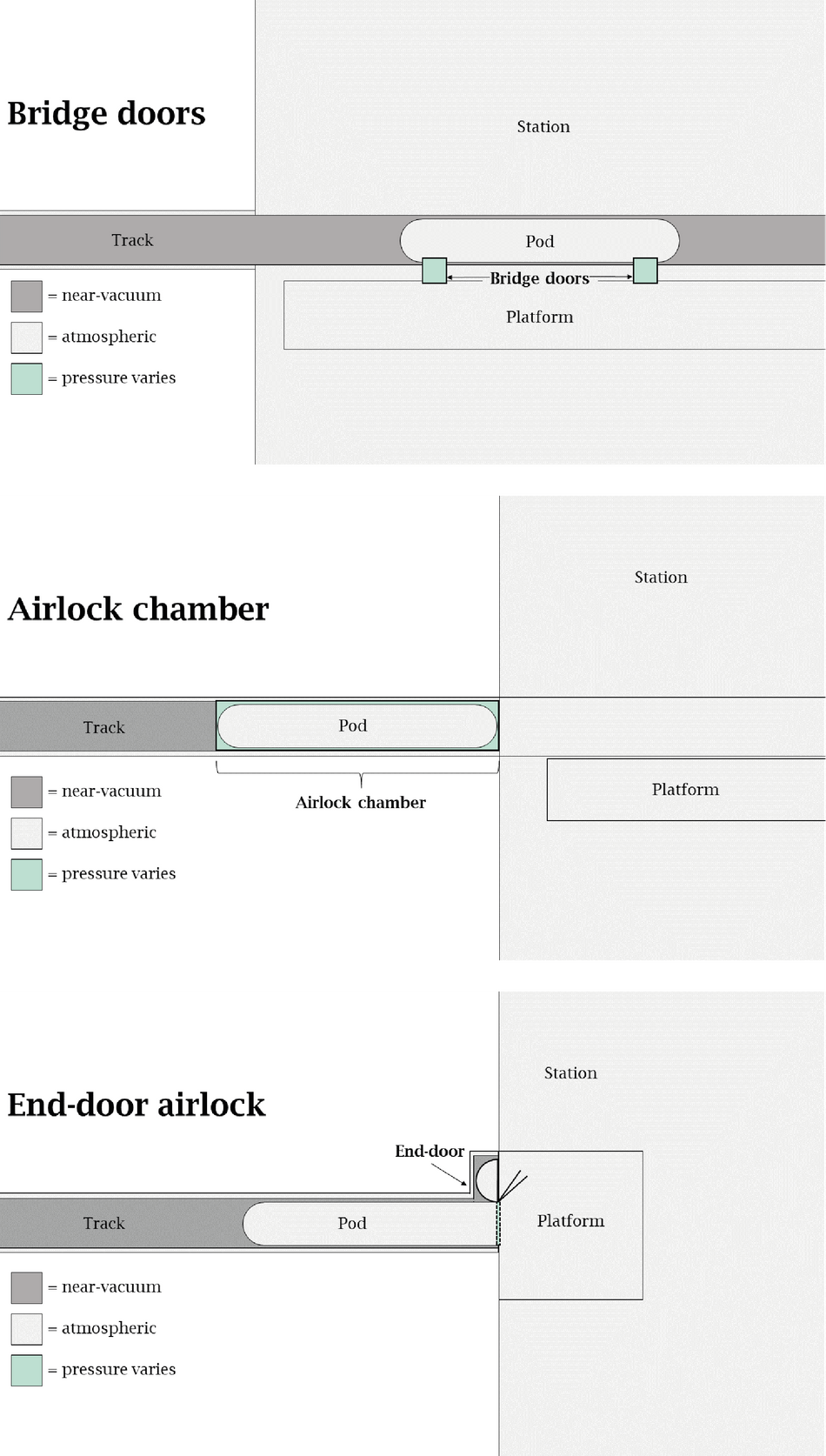
After a thorough analysis, we concluded that the bridge door airlock option would be the most suitable for a hyperloop station. It is the fastest option due to the small volume that needs to be pressurized and only minimal space inside that station is needed to operate the system, reducing construction costs of the tube and the station.
The Amsterdam hyperloop station will be one of many stations in a European hyperloop network. From Amsterdam, we envision that a passenger can travel in two directions. One track will head towards Brussels and Paris, the other towards Frankfurt. One of the biggest challenges of a hyperloop in Europe is the placement and therefore vertical alignment of the tube. Europe is densely populated, which means it is inevitable that the track will encounter cities, towns and protected nature areas. Highways can be laid around these areas, but a hyperloop track needs to be as straight as possible, since it is very uncomfortable for a passenger to do a sharp turn at 1000 km/h. A good way to avoid these areas is by placing the track underground. This is also aesthetically more pleasing, since there is no big tube running through the landscape. However, this is almost twice as expensive as building above ground or on pillars, since tunnels need to be dug out for the tube to go through.
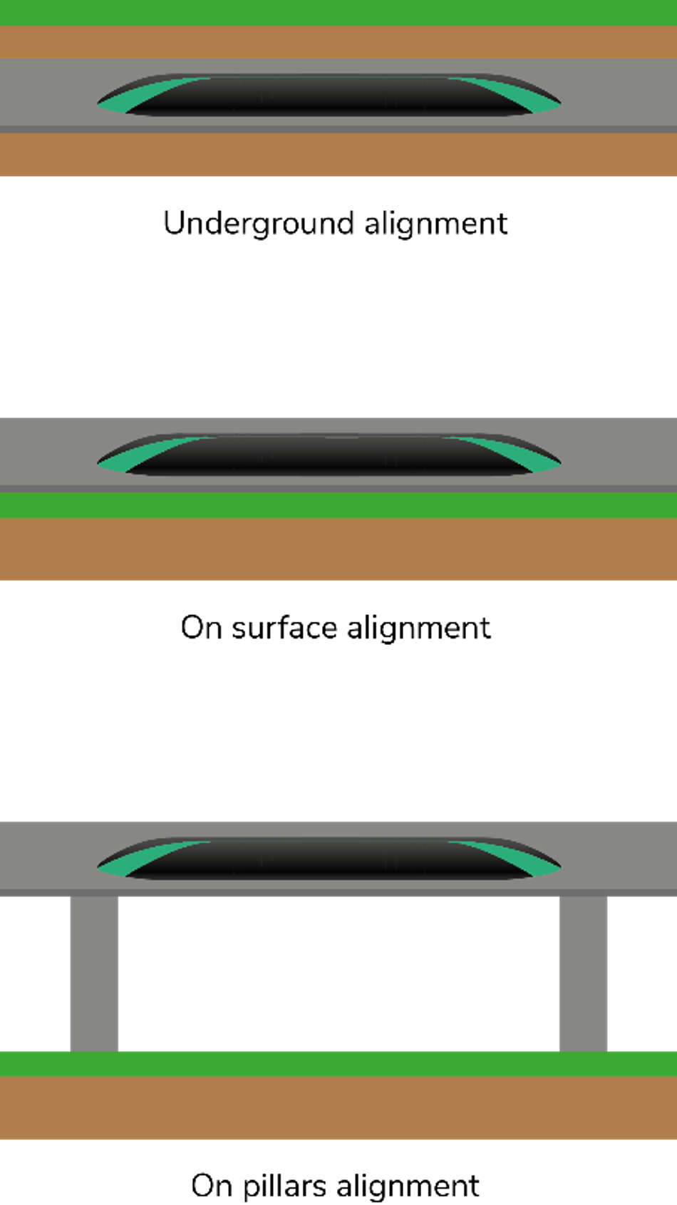
Delft Hyperloop has made a guide for performing a cost-benefit analysis on the vertical alignment of the tube. It considers three types of alignments, on pillars above ground, on the ground and underground. These alignments are shown in Figure 10. The model considers construction costs, maintenance costs, protection costs, energy generation and land acquisition. We applied our model to the track between Amsterdam and Brussels. The results of our analysis are shown in Figure 11.

Figure 11: Results of a cost-benefit analysis of the vertical alignment of the track between Amsterdam and Brussels. Aesthetics and nature benefits are not monetized, resulting in a much higher cost for an underground placement of the tube.
Upcoming year, we will focus more on the infrastructure of the hyperloop and tackling challenges to help realize the hyperloop concept. Furthermore, we will look more in depth into our station and pod design to create the ultimate passenger experience.
The Team
Delft Hyperloop is a team consisting of 35 students from Delft University of Technology. Our mission is to develop the desire, technology and infrastructure for the future implementation of the hyperloop system. We do this by competing in the European Hyperloop Week (EHW) with 25 other universities from all over the world. Next year we are aiming to develop a levitating pod. If you would like to read more about our mission and progress you can visit delfthyperloop.nl or follow us on our socials.
Figure 12: Team photo of Delft Hyperloop V
References
Han-Wook Choa, Hyung-Seok Han, Je-Sung Bang, Ho-Kyung Sung, and Byung-Hyun Kim (2009) ‘Characteristic analysis of electrodynamic suspension device with permanent magnet Halbach array’. Journal of Applied Physics 105