Climb vs Conventional Milling: A Comprehensive Comparison
In the milling industry, two cutting techniques stand out: climb milling and conventional milling. While both techniques are important in the industry, understanding the differences between the two techniques can impact the quality and efficiency of the product.

15 May, 2024. 21 minutes read

Milling Basics
Whether manufacturers opt for climb vs conventional milling, both methods are like sculpting, but with metal and plastic, rather than clay. The metal or plastic workpiece is first clamped onto a platform called the milling machine table or bed. Then the cutting tool or rotary cutter moves along different axes to cut and sculpt the workpiece.
Parts of a Milling Machine
- The Spindle: The spindle holds and rotates the cutting tool. They are available in different types, such as horizontal spindles or multi-axis spindles.
- Drive System (or Head): The drive system transfers power from the motor to the spindle.
- Axis Configurations: The axes control the cutting tool's movements. Most milling machines have three axes: the X-axis (running horizontally), the Y-axis (running forward and backwards), and the Z-axis (running vertically).
- Control System: The CNC (Computer Numerical Control) system is the brain behind the milling machine, dictating how the machine will cut.
Tool Geometry and Cutting Parameters
Selecting the right tool geometry for milling operations is crucial. Like a sculptor choosing between a pointed chisel for details or a flat chisel for wider strokes, the shape of the tool's cutting edge - or geometry - determines the final finish of the workpiece.
Cutting parameters is also an important part of the milling process. The cutting parameters define the speed, depth of the cut, and how fast the rotary cutter moves (its feed rate). Tweaking the cutting parameters helps with efficiency and precision.
Climb or Down Milling
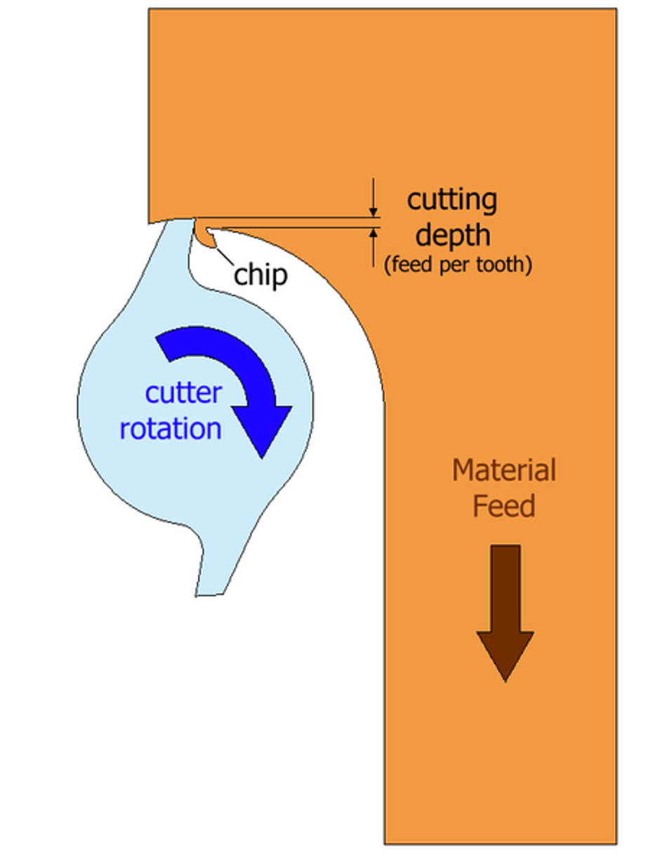
The climb or down milling technique involves rotating the cutting tool in the same direction as the workpiece's feed motion. So, if the rotary cutter is turning clockwise, the feed direction is going to the right.
Because the rotary cutter is turning in the same direction as the feed direction, the teeth of the cutter chip away at the material from the top, working in a downward motion. Climb milling is frequently called down milling.[1]
The Advantages of Climb Milling
- Surface Finish: By rotating the rotary cutter in the same direction the workpiece feed is moving, you'll achieve a smoother surface finish. This is the same as cutting wood with the grain as opposed to cutting against it.
- Reduced Tool Wear: The wear and tear on your tools decreases when you use the climb cut as there is less force on the cutting edges.
Additional Factors That Affect the Performance of the Climb Milling Technique
- Rake Angles: The rake angle is the angle at which the rotary cutter touches the edge of the workpiece material. It may be positive, negative, or neutral. The rake angle affects resistance, the amount of cutting chips produced, the heat due to the cutting action, and the wear and tear on the cutting tool.
- Clearance Angles: The clearance angle is the angle that allows the cut chips to move away from the workpiece.[2]
- Nose Radii: The nose radius is the rounded edges at the tip of the rotary cutter. The nose radius is rounded to prevent breakage during the climb milling process. A large nose radius is used when strength is a priority whereas a small nose radius is used with more detailed sculpting work. The typical nose radius for conventional cutting tools is 0.6 – 1.5mm. For more detailed and precise work, small nose radii are required.[3]
Conventional or Up Milling
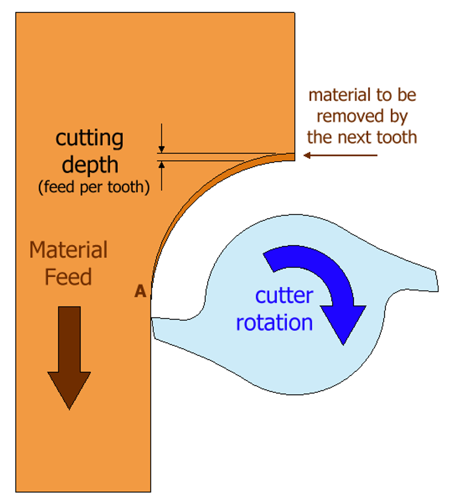
In conventional milling, the rotary cutter rotates against the feed of the workpiece. Think of it as rowing a boat against the current. As the rotary cutter pushes against the material and works upward, it exerts force, and chips away at the workpiece.
The Advantages of Conventional Milling
- Chip Evacuation: When cutting upward or against the feed direction, the chips are automatically pushed away from the cutting area. This prevents the chips from building up on the workpiece.
- Reduced Tool Deflection: Tool deflection in conventional milling is parallel to the cut. This parallel direction results in the tool bending less.
Recommended Readings: 4 Tips for Reducing Tool Deflection in CNC Machining
Additional Factors That Affect the Performance of the Conventional Milling Technique
- Cutting Speed: Cutting speed refers to how fast the rotary cutter rotates. It is measured in surface feet per minute (SFPM) or meters per minute (m/min).
- Feed Rate: The feed rate is how fast the rotary cutter cuts into the workpiece. It is measured in inches per minute (IPM) or millimeters per minute (mm/min).
- Depth of the Cut: The depth of the cut measures how deep into the workpiece the rotary cutter cuts. It is measured in inches or millimeters.
Finding the right balance between cutting speed, feed rate, and depth of the cut can ensure precision and efficiency during the cutting process.
Suggested Readings: Ion Milling: A Comprehensive Guide to Material Etching Techniques
Suggested Readings: Milling Formulas and Definitions
Technological Advancements
1. High-Speed Machining (HSM)
High-Speed Machining pushes both the climb and conventional milling techniques to their limits to increase productivity, achieve better surface finishes, and obtain faster material removal rates. The idea behind HSM is to make very fast, light, low-pressure cuts.
The main benefit of HSM is that it increases productivity. Manufacturers can produce more parts at a low cost, without sacrificing quality.
HSM also uses faster feed rates, higher spindle speeds (above 15,000 RPM), and multi-axis machines. This results in better surface finishes and more precise work. Moreover, the light, low-pressure cuts translate into less stress being put on the machine and less heat generated, extending its lifespan.
When HSM is used with climb milling, you'll get improved surface finishes and efficient production times. On the other hand, HSM isn't always ideal for conventional milling as HSM toolpaths don't always work well with conventional milling machines.
Ultimately, the choice between using HSM with climb milling vs. conventional milling will depend on factors such as the workpiece material, the machine being used, and the type of cuts required.[5]
HSM Applications in Various Industries
Aerospace
HSM is beneficial in an industry where precision and fast production times are paramount. HSM is used to manufacture and assemble the Boeing F/A-18E/F tactical fighter plane, for example. The HSM process allows large structural components to be manufactured in one piece as opposed to being manufactured separately and assembled later. This means 42% fewer parts are being used to manufacture the plane. HSM is also used for turbine blades and aircraft engine parts using spindle RPM speeds of between 18,000 and 40,000 RPM.[6]
Automotive
HSM is used in the automotive to manufacture high-quality parts, such as brake discs, transmission components, suspension parts, and engine blocks, en masse. The automotive industry also uses HSM to produce fast, less expensive vehicles that are lighter in weight.
Medical
Using HSM in the medical industry has proven to be especially beneficial due to the need for precise specifications required in many medical instruments. Some medical devices that use HSM include diagnostic equipment and surgical instruments.[7]
HSM Cutting Parameters
- Cutting Speed: HSM applications use much faster cutting speeds than traditional machining systems, with a range of 500 to 5000 SFPM being typical.
- Feed Rate: HSM applications use feed rates that are more precise and finer. Climb milling can use higher feed rates to help maximize efficiency. Conventional milling, on the other hand, may need lower feed rates to help maintain stability.
- Depth of Cut: HSM applications make quick, low-pressure cuts which can help prevent overheating in the cutting area.
2. Advanced Cutting Tool Materials
Carbide Inserts
One revolutionary material has been carbide as it can remain intact at high speeds and it can withstand high temperatures. Rotary cutters with carbide inserts offer extended lifespans and improved productivity.
When used with climb or conventional milling, carbide inserts provide smooth finishes and high-quality results. The hardness of carbide, which ranges from 1,300 and 1,800 HV, makes it a good choice for high-speed machining operations as well. For this reason, carbide inserts dominate the industry.
There are many grades of carbide inserts to choose from, and industries tend to have their preferences. The aerospace industry typically uses carbide inserts for very tough, heat-resistant superalloys, for example, while the automotive industry uses carbide inserts that can cut into cast iron and low-carbon steel.[9]
Ceramic Inserts
Another development has been ceramic inserts. Like carbide, ceramic inserts are exceptionally hard, with a hardness between 2,100 – 2,400 HV. They can also withstand high temperatures. While carbide can be used for more applications and is often the go-to choice, ceramic inserts are still ideal when cutting heat-resistant alloys and hardened steels.
Ceramic inserts aren't as widely used due to their high price, but they're a good choice for more challenging workpiece materials, whether in climb or conventional milling. The material used for these inserts includes Silicon Nitride Si3N4 or Aluminum Oxide Al2O3 [10]
High-Speed Steel (HSS)
While not as durable as ceramic or carbide inserts, HSS tools also offer reliable performance. Machinists typically use them for machining softer materials. The tool is an iron-based alloy made from tungsten and molybdenum. Other alloy options include chromium, vanadium, and cobalt.[8]
Diamond-Coated Tools
Diamond-coated tools are often a specialized tool, especially in cases where ultra-precision machining is needed. These rotary cutters have a diamond coating of about 0.5 – 2.5 microns thick on the cutting edge to give them an extra layer of hardness.[9] Diamond-coated tools are used for abrasive materials or for clients needing very fine surface finishes. There are two types of diamond-coated tools: CVD thick-film diamonds and Polycrystalline diamonds (PCD).[10]
3. Computer-Aided Manufacturing (CAM) Software
Computer-aided manufacturing (CAM) software guides the milling machine to make precise cuts. It essentially translates 2D drawings or detailed 3D models into instructions for the machine to understand and follow.
CAM software analyzes all the factors needed - feed rate, depth of the cut, cutting speed - and decides the most efficient way to achieve the final design. It also has simulation capabilities that allow operators to perform a virtual test run before starting the machining process. These test runs can significantly reduce errors.
Here are some tool path optimization and simulation capabilities CAM software offers:
- Adaptive Clearing: This feature continually readjusts the tool path based on the remaining material.
- High-Speed Machining (HSM): The HSM feature reduces cycle times, minimizes tool deflection, and improves surface finishes.
- Trochoidal Milling: The trochoidal milling technique uses circular toothpaths so that there is a "softer" entry and exit into and out of the workpiece material. This helps reduce the amount of heat generated.[13]
- Rest Machining: Rest machining removes material left behind from the previous cut to reduce wear and tear on the rotary cutter.
- Simulation Capabilities: Machinists can perform test runs before they are actually executed.
Some popular CAM software packages include Autodesk Fusion 360, Mastercam, SolidCAM, HSMWorks, and CAMWorks.
Applications in Engineering
Aerospace Industry
Climb or Down Milling Applications
- Aircraft Structures: When lightweight materials are used, such as aluminum, climb or down milling is preferred as it can better prevent material damage or deformation compared to conventional milling.
- Aircraft Engine Components: Climb or down milling allows for precise cuts with tight tolerances.
- Aircraft Landing Gear Parts: Both climb and conventional milling are used for landing gear parts. The choice of milling technique depends on the material used.
Conventional Milling Applications
- Wing Spar: Conventional milling is used for machining the wing spar section of an aircraft's wing. This technique ensures stability during the machining process.
- Aircraft Interior Components: Aircraft interiors, such as cabin seat frames, are often manufactured using conventional milling techniques.
Quality and Performance: Climb vs Conventional Milling
- Dimensional accuracy: Climb or down milling can provide dimensional accuracy as the method maintains tight tolerances. On the other hand, conventional milling can shape large-scale parts where stability and control over the workpiece material are crucial.
- Surface Finish: In components where smooth surfaces are essential, such as fuselage panels, climb milling is preferred.
- Material Integrity: Climb or down milling is less likely to cause damage or thermal distortion to the workpiece material.
- Manufacturing Efficiency: The choice of climb vs conventional milling can affect productivity and manufacturing efficiency. Climb milling can provide faster material removal, which can be helpful when meeting tight deadlines.
Machining Parameters and Tool Selections for Aerospace Applications
Cutting Speed: Higher cutting speeds are preferred in the aerospace industry as they reduce the cycle times and speed up production. Typical spindle speeds range from 18,000 up to 40,000 RPM.[6]
- Feed Rate: The feed rate (IPM) must be balanced with the cutting speed and spindle speed to increase productivity and minimize chatter (the vibrations of the rotary cutter).
- Depth of Cut: Aerospace components need hardened materials to endure stress and high temperatures. Still, the depth of the cut must be controlled to prevent tool deflection and to manage the cutting forces.
- Tool Selections: Carbide inserts are often the go-to tool as they can cut a wide range of hard materials like titanium or carbon fiber reinforced plastics (CFRP).
- Tool Geometry: The rake angles and edge configurations must also be customized for the specific job. As an example, materials like nickel alloys need a high positive rake angle to reduce the cutting force.[14]
- Tool Coatings: Tool coatings, such as TiAlN (titanium aluminum nitride) or TiCN (titanium carbonitride), can help reduce heat in the localized cutting area as well as reduce friction. Coating the rotary cutter can extend its life as well.
Automotive Industry
Climb or Down Milling Applications
- Cylinder Heads: Down milling is often used to manufacture cylinder heads as the technique can provide tight tolerances for combustion chamber volume and valve seat concentricity as well as precise dimensional accuracy and smooth surface finishes.
- Shafts and Gears: Down milling ensures precise control over details like chip evacuation and the cutting forces. Precision is essential for keyway slots and gear tooth dimensions.
- Body Panels: Down milling is often used for exterior body panels. This includes fenders, hoods, and doors. The technique is used to ensure accurate hinge cutouts, mounting hole locations, and window regulator openings.
Conventional or Up Milling Applications
- Engine Blocks: Large-scale engine blocks made from cast iron or aluminum do better with conventional milling as they require stability during the machining process as well as precision with the bore diameters and deck heights.
- Chassis and Suspension Parts: Control arms, sway bars, and steering knuckles are manufactured using the conventional milling technique. Control arms need stability and precise work for their ball joint seat dimensions and bushing bore diameters, for example.
Efficiency and Cost-Effectiveness: Climb vs Conventional Milling
The choice between climb vs conventional milling can affect the following:
- Material Removal Rates: Climb or down milling provides faster removal rates compared to conventional milling. This means shorter machining times and therefore lower manufacturing costs.
- Tool Wear: As climb or down milling doesn't exert as much force on the rotary cutter, the method can prolong tool life compared to conventional milling. This often means lower costs for rotary cutters and lower production expenses.
- Surface Finish: For smaller components, climb or down milling provides smoother surface finishes. For larger-scale components, where stability when machining is crucial, conventional milling is a better option.
- Complexity of the Design: For components with tight tolerances and intricate details, climb or down milling is preferred. However, for large-scale parts with simple designs, conventional milling is a better choice.
Machining Parameters and Tool Selections for Automotive Applications
- Cutting Speed: Higher cutting speeds tend to be preferred for increased productivity, like the M5F90 machine, which offers above 15,000 RPM spindle speeds.
- Feed Rate: Feed rates and cutting speeds must be balanced to reduce tool wear while ensuring dimensional accuracy. A typical feed rate is 0.16 mm/tooth.
- Depth of Cut: Controlling the depth of cut helps minimize tool deflection while still achieving precision when cutting through aluminum, steel, or cast iron alloys. A typical depth of cut is 1.5 mm (0.06 inch), though this depends on the workpiece material and component.
- Tool Material: The choice of tool material is crucial. Carbide and high-speed steel inserts are commonly used to handle automotive materials.
- Tool Geometry: The tool geometry must be tailored to the specific automotive job as each project presents different challenges.
- Tool Coatings: Tool coatings, such as TiAlN (titanium aluminum nitride) or TiCN (titanium carbonitride), can help extend tool life and minimize the material sticking to the tool.
Medical Device Manufacturing
Climb or Down Milling Applications
- Orthopedic Implants: Orthopedic implants for hip and knee replacements, for example, typically use the down milling technique. One reason is to ensure high-quality surface finishes on biocompatible materials, like cobalt chrome or titanium alloys. The dimensions and shapes must be customized to the body they are replacing, so tolerances must be within a few microns, and surface finishes require 0.2 microns or less Ra (roughness).
- Tibial Trays: Tibial trays are part of artificial knees and must be machined with no sharp edges. Moreover, the tight tolerances require the down milling technique.[19]
- Dental Implants and Components: Titanium dental implants must be customized to fit into the patient's bone sockets. The down milling technique is used as it can ensure tight tolerances in the range of ±0.005 mm.
- Bone Plates and Screws: Bone plates and screws are typically made from titanium or stainless steel. Since they must be customized and match the contour of the patient's bone, tight tolerances within ±0.01 mm are required.
- Heart Valves: Heart valves are made from titanium or specialized plastics and require very smooth surface finishes to prevent blood clot formation. They also need tight tolerances of below ±0.005 mm.
Conventional or Up Milling Applications
- Pacemaker Cases and Components: Pacemaker cases must be strong to protect the electronic components inside. This robust design makes it ideal for the conventional milling technique.
Precision and Surface Finish: Climb vs Conventional Milling
For a high-quality surface finish and precise work with tight tolerances, the climb or down milling technique is the preferred method. High-quality surface finishes can also improve biocompatibility and reduce the risk of bacterial growth.
On the other hand, in cases where you are working with very hard materials or you need to remove large amounts of material, conventional milling is a good choice. The technique allows machinists to handle hard materials without a lot of wear on the cutting tool.
Machining Parameters and Tool Selections for Medical Devices
- Material: The materials used in the medical industry include titanium, stainless steel, cobalt-chromium alloys, and plastic. When working with titanium and cobalt-chromium alloys, diamond-coated or carbide tools can effectively machine these materials. Plastics, on the other hand, do well when high-speed steel tools are used.
- Cutting Speed: Although faster cutting speeds tend to speed up production, the medical industry tends to use slower speeds to prevent overheating.
- Feed Rate: While the automotive and aerospace industries prefer faster feed rates, the medical industry prefers to prioritize surface finish over feed rate as a fast speed rate can compromise surface finishes.
- Depth of Cut: Given the size of many medical devices, lighter cuts are often necessary for customized implants, bone plates, bone screws, and heart valves.
- Tool Geometry: Tools used for medical devices typically have very specific geometries, such as larger flutes.
- Coatings: Some coatings used include diamond-like carbon (DLC) and titanium nitride (TiN).
Case Studies
Case Study 1: Aerospace Component Manufacturing Manufacturing of Aircraft Turbine Blades Using Climb Milling
Turbine blades are an important part of an aircraft as they must function efficiently at high stresses and high temperatures. The material used to make turbine blades is advanced superalloys, such as Inconel 718. However, due to their hardness, these materials can be challenging to work with.
Challenges
- High temperatures: High temperatures can alter the superalloys, weakening the blades.
- Surface imperfections: Any surface imperfections can compromise the performance.
- Tool wear: Due to the hardness of superalloys, they can cause fast tool wear.
Solutions
To produce aircraft turbine blades, climb or down milling is preferred. The technique ensures smoother surface finishes.
To prevent overheating, high-pressure coolant systems are used. This keeps the temperatures lower and prevents overheating.
To cut through the hardness of superalloys, carbide-coated tools or diamond-coated tools (polycrystalline diamond) are used.
Finally, CNC milling precisely controls the feed rate and speed needed to produce the turbine blades.
Benefits
- Better surface finish
- Better tool life
- Increased manufacturing output via CNC machining methods
Case Study 2: Machining of an Automotive Engine Block Using Conventional Milling
The engine block houses a vehicle's cylinders, coolant passages, and crankcase, making it a crucial part of a vehicle. Engine blocks are made from aluminum or cast iron alloys. Aluminum is typically used to keep vehicles lighter. However, the material's softness can become a challenge during the machining process.
Challenges
- Distortion when cutting due to soft, malleable material
- Aluminum and cast iron alloys can be abrasive, eventually wearing down tools
- A smooth surface finish can be hard to maintain
Solutions
- Conventional milling cuts against the feed direction. This makes it beneficial for softer materials, such as aluminum, as there is less risk of a "built-up edge" or the material sticking to the tool.
- To reduce wear and clogging, carbide-insert tools with titanium aluminum nitride (TiAlN) coatings are used.
- Specific coolants are used to maintain a lower temperature. This can prevent overheating and provide high-quality surface finishes.
Benefits
The convention milling method allows machinists to combine machining parts into one setup. Instead of using a resurfacing machine, a milling machine, and a boring machine, just one machining setup with different axes and a variety of tools is required.[17]
Challenges and Considerations
1. Tool Deflection and Chatter
Tool Deflection
Tool deflection is when the cutting tool bends during the machining process. Not only can tool deflection throw the tool off of its original path, but it can also lead to inaccuracies in the cutting.
Tool deflection can be a result of the material being used, the length and diameter of the rotary cutter, and the cutting parameters. Harder materials and deeper cuts increase the risk of tool deflection.
Tool deflection tends to be more pronounced in conventional milling as the cutter teeth enter the material at a minimum thickness and exit at a maximum thickness. This can cause the workpiece to be pulled towards the rotary cutter, resulting in tool deflection.
To prevent this from occurring, it is often best to use short, rigid tools. Machinists can also reduce the depth of the cut. Finally, they can improve how the workpiece is clamped to the machine table so it isn't pulled toward the cutting tool during the machining process.
Chatter
Chatter occurs when the rotary cutter or workpiece resonates during the machining process. This can lead to low-quality surface finishes and imperfections in the finished work.
Chatter is caused by a mismatch between the frequencies of the rotary cutter and the frequencies of the cutting machine. Factors that contribute to chatter include tool wear, spindle speed, and the work setup.
To minimize chatter, machinists must fine-tune spindle speeds and feed rates, based on what they are manufacturing. Reducing spindle speeds can reduce chatter, but increasing spindle speeds can reduce chatter, too. In the automotive industry, some manufacturers increase chatter so the machine vibrates at the same frequency as the cutter tool.[6]
Additional factors that can mitigate chatter and tool deflection include:
Tool Stiffness: By using stiff carbide inserts and shortening the length of the tool extension, chatter and tool deflection can be reduced.
Cutting Force: Machining hard materials or making deep cuts can cause tool deflection. To minimize this, helical milling and ramping can be used to distribute the force of the machine evenly.[18] Chatter can be minimized by adjusting the feed rate and cutting speed.
Machine Rigidity: More rigid machines can better resist vibrations and provide more stable conditions. To improve machine rigidity, more robust clamps and fixtures can be used.
2. Chip Formation and Evacuation
Chip Formation
When using the climb or down milling technique, the rotary cutter enters the workpiece material at its maximum thickness and exits at the minimum thickness. This pattern, called a thick-to-thin pattern, reduces the load on the cutting edge of the rotary cutter. The chips formed start thick and thin out. Less force on the rotary cutter and less heat generated usually result in a longer lifespan for the cutting tool.
In conventional milling, the reverse happens. The rotary cutter enters the workpiece material at its thinnest point and exits at its maximum thickness. The chips formed start thin and gradually increase in thickness. This action puts more stress on the rotary cutter. As a result, it can result in tool deflection, more heat generated, and a shorter lifespan for the cutting tool. Exiting the workpiece material at the maximum chip thickness can also lift the material slightly, causing inaccuracies when cutting.
Chip Evacuation
The climb cut pushes the chips in front of the rotary cutter, in the same direction as the feed. The technique minimizes the risk of re-cutting chips.
In conventional or up milling, the chips are pushed up and back over the cutting tool, landing on the rotary cutter as well as the just-cut surface. This can result in chips being re-cut and possibly damaging the smooth workpiece surface.
How to Optimize Chip Formation and Evacuation
Climb or Down Milling
- Balance the Parameters: Balance the right spindle speed with the feed rate. For example, higher speeds can create thinner and more manageable chips. Shallower cuts can also ensure thinner chips.
- Tool Selection: Choose tools with polished flutes and higher helix angles. Higher helix angles are less likely to bend or vibrate during the cutting process, while polished flutes help reduce the load on the cutting tool.[15]
- Coolant Systems: If the accumulated chips are left in the cutting area, heat can build up. To help with this, high-pressure coolant systems can flush any chips away from the cutting area.
Conventional or Up Milling
- Balance the Parameters: Lower spindle speeds minimize the localized heat, and less heat can prevent the hardening of materials. This combination helps optimize chip formation.
- Use Coating: Tools with coating can provide surface lubricity for the rotary cutter, preventing the chips from sticking to the rotary cutter. Popular coatings include TiCN (Titanium CarboNitride) or AlTiN (Aluminum Titanium Nitride).
- Air Blasts: Air blasts can blow the chips away from the cutting area quickly.
- Fixtures and Clamps: Ensure the clamping is strong to prevent slight lifting when the rotary cutter exits the material.
3. Workpiece Material and Geometry
Workpiece Material
When choosing climb vs conventional milling, the workpiece material plays a major role.
- Hardness: Conventional milling is the preferred option when the material is particularly hard. Softer materials that require more precision tend to use climb or down milling.
- Work Hardening Tendencies: Some materials, like stainless steel, tend to harden when cut into. This can make conventional milling a very taxing technique since the cut gets thicker as the cutting process continues.
Workpiece Geometry
The workpiece geometry also influences the choice between climb and conventional milling.
- External Cuts: Peripheral or external cuts use the climb milling technique as less stress should be placed on the edge of a workpiece to avoid damaging the workpiece material.
- Internal Cuts: Due to the force needed for internal cuts - such as slots or pockets - the conventional milling technique may be preferable.
- Rigid Setups: In setups where the workpiece material is firmly mounted, the climb or down milling technique is preferred. The rotary cutter pushes the workpiece down onto the table when cutting. This action works well when the setup is stable.
- Less Rigid Setups: If the workpiece could potentially move slightly, the conventional milling technique may prove to be a better choice.
Materials and Geometries Suited for Climb or Down Milling
Materials that form chips easily and are softer work well with the climb or down milling method. These materials include:
- Aluminum
- Non-ferrous metals
- Hard plastics
- Composites
Since the climb cut tends to push the workpiece material with a downward force, against the surface, flat or horizontal geometries are best suited for this method.
Materials and Geometries Suited for Conventional or Up Milling
Hardened materials tend to produce the best results with conventional milling techniques as the thin-to-thick cutting style helps manage the cutting forces better. These materials include:
- Hardened steels
- Hard-to-machine alloys
- Brittle materials
When the rotary cutter must enter and exit the workpiece frequently, such as creating slots and pockets, then conventional milling can maintain better control during the cutting process. Long workpiece materials with less rigid setups can also benefit from the conventional milling technique.
Properties of Different Workpiece Materials
Aluminum
Aluminum is a soft, ductile metal, which makes it easy to cut. This quality can result in burring - small metal particles that stick to the workpiece material's surface.[16]
When cutting aluminum, the climb or down milling technique is used as it provides a cleaner cut. This cleaner cut minimizes both the buildup on the tool's surface and burring.
Stainless Steel
Not only is stainless steel tough, but it also tends to harden during the cutting process. It also has a lower thermal conductivity than aluminum, for example, causing heat to concentrate in the cutting area rather than move through the material.
These features make conventional milling a better choice when machining stainless steel. The thin-to-thick cutting style used also helps distribute heat more effectively.
Titanium
Titanium is a strong metal and resistant to heat, which can make it challenging to machine. In addition, it can also react chemically with the rotary cutter at very high temperatures.
To prevent overheating, the climb or down milling technique is often used. This technique also ensures better chip evacuation, which also prevents heat buildup in the cutting area.
Hardened Steels
Hardened steels tend to be brittle and can crack under high forces or heat. For this reason, conventional milling is a better choice when machining hardened steels. The thin-to-thick cutting style eases the rotary cutter into the material, preventing the workpiece material from cracking.
Plastics and Composites
Plastics and composites can range from either soft and flexible or hard and brittle. They can also melt easily, or they can be abrasive. However, the most preferred method with plastics and composites is climb or down milling as this technique is less likely to deform the workpiece material.
Conclusion
The key differences between climb and conventional milling are how the rotary cutter enters and exits the material and the direction of the workpiece's feed relative to the rotation of the cutter. These differences make climb milling better for smoother surface finishes and tighter tolerances and conventional milling better for simpler designs and harder materials.
When selecting climb vs conventional milling, the choice will depend on a variety of factors. Some factors include the workpiece material being cut, the requirements of the project, and the intricacy of the final design.
Advancements in milling, specifically with the integration of AI, are quickly transforming the manufacturing industry. With better precision, smoother surface finishes, increased overall productivity, and better control systems, the industry is set to see some significant changes.
Frequently Asked Questions
How do climb and conventional milling affect cutting forces and tool wear?
In climb milling, cutting forces are lower as the material being cut goes in the same direction as the workpiece material's feed. This typically results in reduced tool wear and longer lifespans for the cutting tools. Conventional milling has higher cutting forces and more tool wear due to the material being cut in the opposite direction of the workpiece material's feed.
What are the advantages of climb milling?
Climb or down milling tends to be the go-to choice for many manufacturers because it offers smoother surface finishes, less wear and tear on the tools, better precision, and tighter tolerances.
When should I use climb milling versus conventional milling?
If tighter tolerances and very smooth surface finishes are a priority, then the climb or down milling technique should be used. If the design is simpler, the workpiece material is very hard, and stability is paramount when machining, then conventional milling should be used.
How do I select cutting parameters and tool geometries for climb and conventional milling?
The cutting parameters and tool geometries will largely depend on the workpiece material and the final design. The parameters will also be influenced by whether you're making an interior cut or an exterior cut.
What role does toolpath optimization play in climb and conventional milling?
Toolpath optimization is critical for both climb and conventional milling. If heat buildup is an issue, for example, machinists can use trochoidal milling to reduce heat buildup in the cutting area. CAM software can also be used to optimize toolpaths for either milling technique to ensure that the property of the material and the tool geometries are taken into consideration. Toolpath optimization can also reduce tool wear and minimize cycle times to increase productivity.
References
[1] Datron. Climb Milling vs Conventional Milling. Link
[2] Difference Box. Rake Angle. Link
[3] Minaprem. Nose Radius. Link
[4] Grainger. HSM. Link
[5] Peakedm. High Speed Machining - History, comparison, and more. Link
[6] Mmsonline. HSM in Aerospace. Link
[7] HartfordTechnologies. Industries relying on HSM. Link
[8] Wikipedia. HSS. Link
[9] Kennametal. Selecting Carbide. Link
[10] Mtwmag. Where to use Ceramic inserts. Link
[11] Harveyperformance. Diamond End Mills. Links
[12] Carmex. PCD & CVD inserts. Link
[13] Ceratizit. Trochoidal Turning with CAM. Link
[14] Etherealmachines. Advancement of aerospace industry with machining. Link
[15] Huanatools. Choosing the right helix angle. Link
[16] Machining Custom. How to Reduce Burrs when CNC Machining Aluminum Parts? Link
[17] Motor. CNC machining an engine block. Link
[18] ScienceDirect. A review of helical milling process. Link
[19] Mscdirect. 5 ways cutting tools benefir medical implant manufacturers. Link
in this article
1. Climb or Down Milling2. Conventional or Up Milling1. High-Speed Machining (HSM)2. Advanced Cutting Tool Materials3. Computer-Aided Manufacturing (CAM) Software6. Aerospace Industry7. Automotive Industry8. Medical Device Manufacturing9. Case Study 2: Machining of an Automotive Engine Block Using Conventional Milling1. Tool Deflection and Chatter2. Chip Formation and Evacuation3. Workpiece Material and Geometry13. Conclusion14. Frequently Asked Questions15. References