Building Reliable Battery Energy Storage Systems
Connectivity, Protection, and Power Solutions by TE Connectivity and Avnet Abacus

06 Aug, 2026. 12 minutes read
Executive Summary
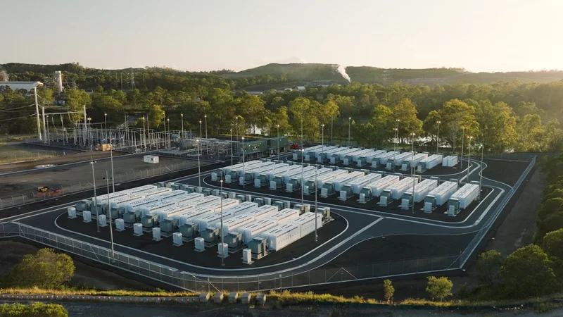
Battery Energy Storage Systems (BESS) have evolved from pilot projects into critical infrastructure underpinning modern energy grids, renewable energy assets, EV charging networks, and industrial energy. As deployments scale and operating lifespan extends to 10-20 years, the engineering challenge extends beyond storing energy to doing so reliably, safely, and economically under long-term electrical and environmental stress.
Most of the time, failures in BESS don’t originate from battery cells; they occur at electrical and mechanical interfaces surrounding them. At utility scale, performance issues and failures can trigger multiple contractual penalties and affect grid stability. In commercial installations, it impacts operations and increases maintenance costs.
BESS designers must therefore select components that deliver precision, durability, and compliance across every subsystem, including Battery Management System (BMS), Power Conversion System (PCS), and Energy Management System (EMS).
TE Connectivity offers a comprehensive portfolio of connectivity and protection technologies purpose-built for the full BESS architecture, spanning high-voltage contactors, ruggedized connectors, electromagnetic interference (EMI) solutions, and functional safety solutions. Avnet Abacus provides manufacturers with streamlined access to these technologies, backed by deep sourcing capability and application expertise.
Introduction
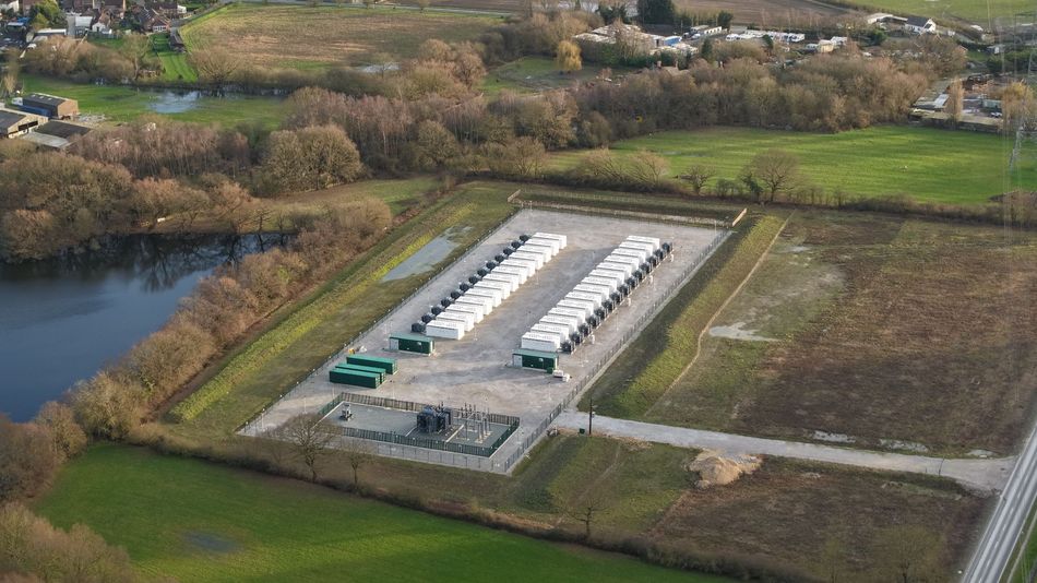
Battery Energy Storage Systems (BESS) are electrochemical systems that capture, store, and dispatch electrical energy as and when needed. BESS, which started as pilot projects in the 2000s for niche applications, have become critical infrastructure across electric grids, renewable generation assets, EV charging networks, and industrial and backup energy applications. As the technology makes its way to more applications, reliability, safety, and efficiency are becoming critical design priorities.
Most BESS platforms today operate under demanding conditions that involve high voltages, elevated currents, thermal stress, electromagnetic interference (EMI), and continuous operation. While batteries and power electronics are the key components of BESS, long-term performance also depends heavily on interconnects, sensors, and protection infrastructure.
Failures in these supporting layers can lead to a number of problems, like overheating, increased downtime, and reduced operational life. Engineers therefore require compact, rugged, and high-performance components capable of supporting reliable operation across the full BESS architecture.
TE Connectivity provides a broad portfolio of connectivity and protection technologies for modern BESS, while Avnet Abacus supports customers with access to these solutions.
Core Components of BESS
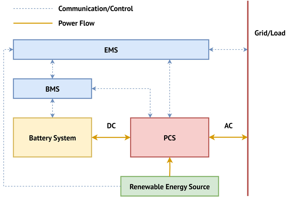
A BESS is made up of multiple interconnected subsystems. These subsystems work together to capture, store, manage, and supply electrical energy safely and efficiently. Battery cells and modules are at the core of these systems, but they are supported by several control and power management layers.
Battery Management System (BMS)
The Battery Management System (BMS) is responsible for monitoring and protecting the battery throughout its operation. It continuously tracks critical parameters such as voltage, temperature, current, and state of charge across individual cells and modules.
The BMS also helps:
- Prevent overcharging and deep discharge
- Enable cell balancing
- Detect faults and abnormal operating conditions
- Managing thermals
Power Conversion System (PCS)
The Power Conversion System (PCS) takes care of power flow between the battery and the grid or connected applications. It is bidirectional in nature, converting stored DC energy into usable AC power and available AC or DC power to DC during charging cycles. PCS platforms operate under high voltages, elevated currents, and high frequencies, all under a continuous thermal load.
Energy Management System (EMS)
The Energy Management System (EMS) is the system-level coordinator of the BESS platform. It interfaces with the external systems and internal subsystems of BESS to control energy flow, enable remote monitoring, and facilitate the optimization of system efficiency depending on operating conditions and operational requirements. Modern EMS platforms are often integrated with Supervisory Control and Data Acquisition (SCADA) systems to monitor and control the process externally in a centralized manner.
System-Level Infrastructure and Protection
Beyond core electronic systems, BESS must also withstand harsh environmental and mechanical conditions. Dust, moisture, vibration, and temperature fluctuations all affect long- term system reliability.
As a result, system-level infrastructure often requires the following:
- Environmental sealing
- Ruggedized connectors
- EMI shielding
- High-voltage isolation
- Safe cable routing and protection
In a lot of cases, failures occur not within the battery itself but at electrical and mechanical interfaces. To avoid failures and ensure long-term BESS performance, reliable interconnect and protection technologies are needed.
Battery Management Systems (BMS): Signal Integrity, Control, and Protection
BMS is the primary control layer of the BESS. It monitors cell-level and pack-level parameters to enable efficient energy utilization across the system. When building the BMS, engineers must ensure that the system can carry out several core functions and meet certain performance requirements.
Accurate Monitoring and Data Collection
The BMS continuously samples key battery parameters like cell voltage, current, and temperature. While different setups place different accuracy requirements, voltage readings typically require an accuracy of ±2-5 mV or better, and the current readings must offer an accuracy of ~0.5% or better. Any deviation in these readings beyond the acceptable limits could affect the estimation of the state of charge (SOC) and the state of health (SOH) for the battery pack.
SOC is a real-time indicator of the capacity of the battery. It is at 100% when the battery is charged and drops gradually as it discharges. BESS operators rely on SOC data for carrying out energy arbitrage, peak shaving, or frequency regulation.
SOH represents the battery’s condition and effects of aging. A brand new battery starts at 100% (or higher) of its designed capacity and drops with repeated charging-discharging cycles. When it drops to 70-80%, BESS operators carry out maintenance.
Signal Integrity and Reliable Communication
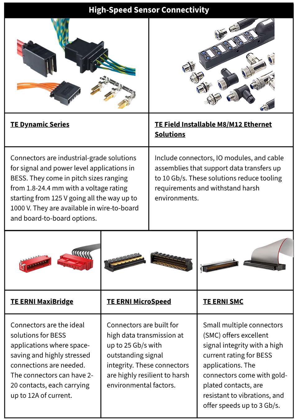
BMS architectures collect and process large volumes of data in real-time. To do so, they rely on various interconnects working in densely integrated electronic environments with signal lines running in close proximity to power lines and other signal lines.
As BESS deployments scale, more cells are added, and modules get more complex; the communication chains grow longer and more hierarchical. In such a scenario, no amount of filtering can correct the inaccuracies introduced by poorly designed components.
Functional Safety and Fault Protection
Another key role of BMS is to enable functional safety for BESS. It is responsible for identifying, notifying, and triggering protective actions during abnormal operating conditions, such as:
- Overvoltage events
- Overcurrent conditions
- Thermal runaway
- Isolation faults
- Communication failures
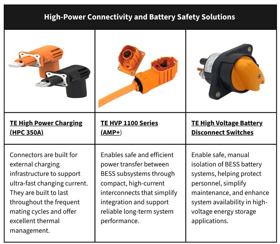
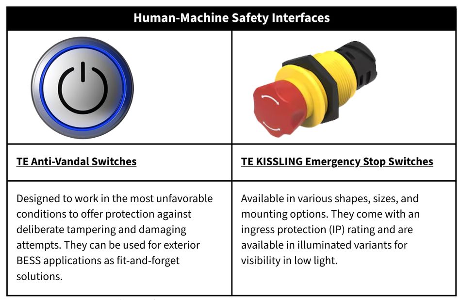
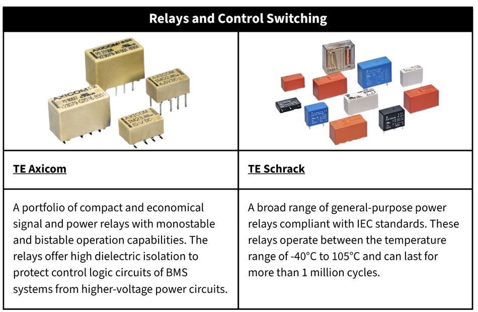
When any of these conditions are detected, the BMS must signal the contactors, relays, or battery disconnect switches to isolate the affected string or the full pack from the system. The reliability and latency of this response path, as the signal travels from the detection logic to the actuation point, determine the reliability of the BMS. Inaccuracies in signal chains can lead to communication dropouts or errors in the measurements, which may end up masking the faults or causing false triggers, both of which are dangerous to the infrastructure and users.
Compact Integration and Space Constraints
For cost reduction in BESS, manufacturers are trying to pack more power capacity in the same footprint. This potentially reduces the cost of the system and the real estate required for deployment. The pressure to make the systems smaller is evident across all the layers of BESS, including the BMS. Enclosures shrink, PCBs are designed with tighter routings, and connectors are made smaller, all while the performance and safety requirements stay the same or even increase with each passing generation.
Power Conversion Systems (PCS): Switching, Filtering, and Thermal Stability
The Power Conversion System (PCS) manages the energy flow between the battery stack, the energy source/electrical grid, and the load. During charging, it converts the source's power into DC, and during discharging, it reverses the process. PCS operates under the most demanding electrical and thermal stress conditions in BESS.
High-Voltage Switching Requirements
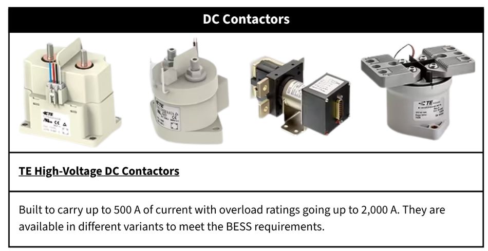
DC bus voltages reach up to 1500 V in modern PCS, driven by needs of reducing conductor losses and inverter counts at scale. At voltage levels as high as this, DC arc extinction becomes the primary challenge for the switching equipment.
Unlike AC systems, where the current naturally touches zero multiple times in a second, DC arcs are self-sustaining and need to be suppressed by external factors like contact geometries and arc-quenching gas environments.
In PCS, components must handle four key modes of operation with different electrical stresses:
- Regular power conversion cycle, where routine charging and discharging takes place.
- Pre-charge sequences, where current ramp-up must be gradual to avoid inrush damage to capacitors and downstream components.
- Faults and emergencies, where currents significantly higher than the rated capacity must be interrupted at high speed.
Thermal Management Challenges
All electrical components generate heat. This is due to the different kinds of losses associated with them. For example, busbars and interconnects heat up due to resistive losses, and power semiconductors generate heat predominantly due to switching losses.
This causes long-term thermal loading on PCS components, which may affect its performance over the long term in several ways. Oxidation occurs faster at contacts, insulation materials age quicker, and switches get less reliable.
To achieve effective thermal design, it is necessary to buy components that will perform over the long term at these operating temperatures. This matters significantly over a period of 10-20 years, which is typical for BESS installations.
EMI Suppression and Signal Stability
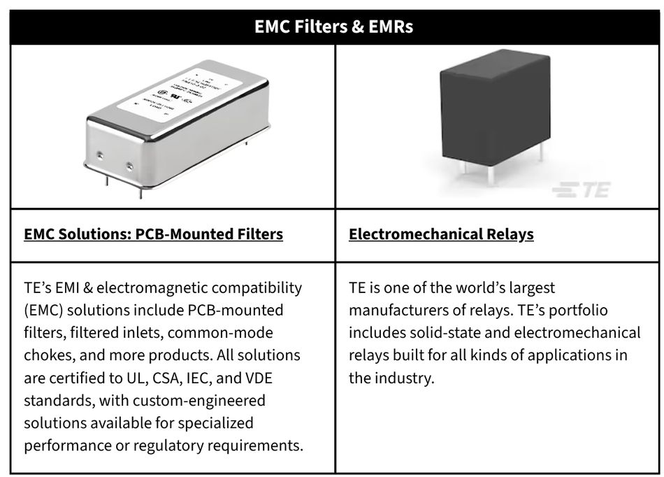
IGBTs and SiC-based inverters generate massive amounts of EMI due to their high switching speeds. In BESS applications, such interference must be suppressed below certain standards and limits, applicable for the installations. Failure to contain the effects of EMI could hinder the operation of protection relays and metering equipment near the PCS.
Within PCS itself, EMI could deteriorate communication over buses and sensor signal lines. Any low-voltage electronics close to the EMI source get affected, creating a requirement for EMI filters, shielded interconnects, grounding solutions, and noise suppression technologies.
Energy Management Systems (EMS): Control, Communication, and System Coordination
While BMS is responsible for managing the battery, and PCS is responsible for power conversion, EMS sits above both to continuously monitor conditions across all the subsystems to optimize energy flows and maintain communication with external systems.
System Coordination and Energy Optimization
The EMS monitors and manages a number of time-sensitive tasks at once, such as:
- Load balancing
- Charge and discharge scheduling
- Peak demand management
- Backup power control
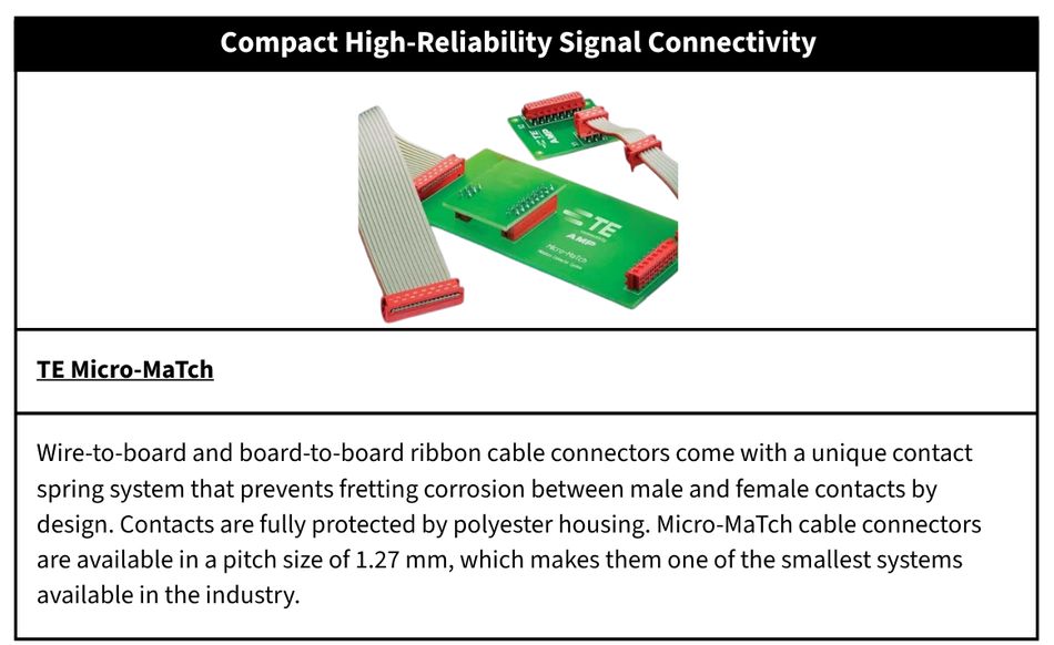
In multi-rack BESS installations, EMS wiring can extend to significant physical distances across battery enclosures and control rooms. Connector systems used for this application must maintain a stable contact resistance, resist harsh environments, support easy routing, and reduce maintenance complexity in the long term.
In grid-connected BESS, external interfaces add more communication reliability constraints, as failures in this case affect the wider grid infrastructure in case of issues.
Scalable Wiring and Infrastructure Design
Scalability is central to BESS. Large-scale BESS deployments are very rarely static in nature. As requirements evolve, they undergo capacity expansions, system upgrades, fault isolations, maintenance, etc. An efficient EMS should be able to handle these infrastructure activities without causing disruptions in the entire BESS.
The use of modular connectors, clear cable identifiers, and organized communication pathways reduces the upgrade and service complexity of the system.
System-Level Integration: Enclosures, Protection, and Harsh Environment Readiness
BMS, PCS, and EMS are all core parts of BESS. As important as it is to pick the right components for these systems, it is equally important to consider the physical infrastructure that supports them and houses them. The consequences of ignoring system-level protection considerations often show up over a long period. In BESS installations, they keep adding up to reliability and maintenance costs over time, which exceed the upfront costs of adequate protection.
Environmental Sealing and Protection
Moisture ingress, dust contamination, and chemical exposure can negatively affect connectors, switching systems, and sensitive electronics throughout a BESS installation.
To improve reliability, system architectures often incorporate:
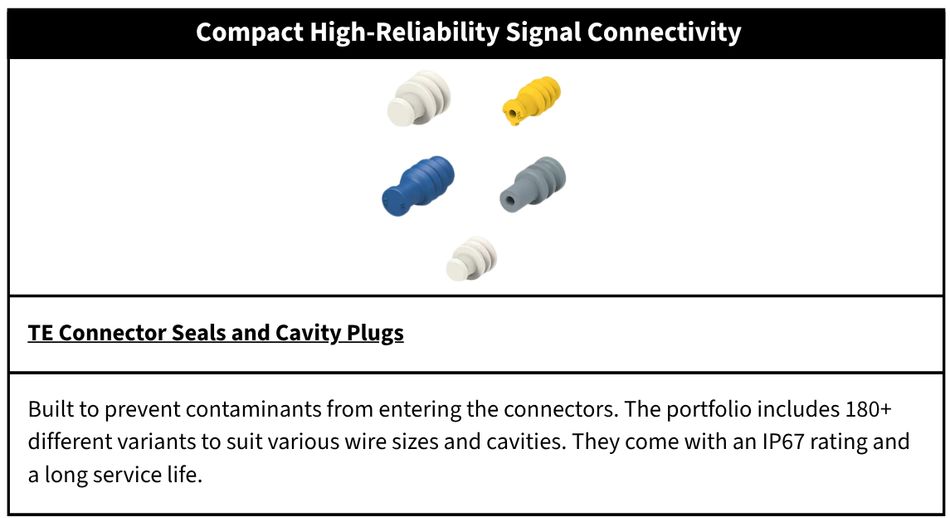
- Environmental seals
- Cavity plugs
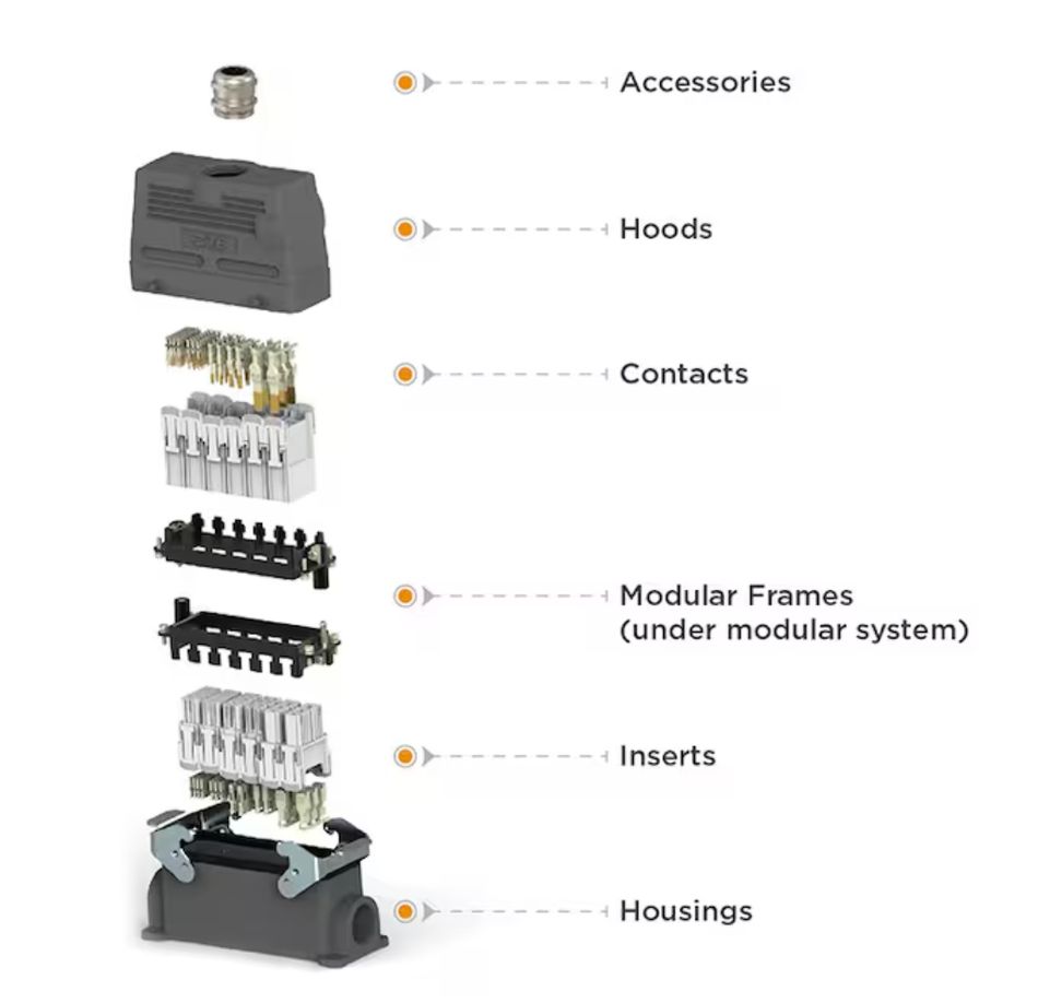
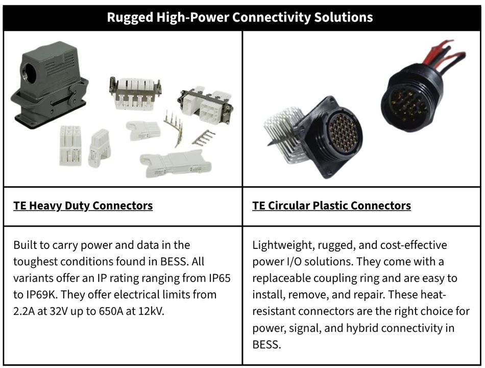
- Ruggedized connector systems
- Protected cable routing
These solutions help maintain enclosure integrity and reduce the risk of electrical failures caused by harsh operating environments.
Mechanical Robustness and Vibration Resistance
There are multiple sources of mechanical stress in BESS. As they undergo repeated heating and cooling cycles, materials undergo thermal expansion on a daily basis. Heating, ventilation, and air conditioning (HVAC) or nearby equipment can introduce vibrations. In many cases, the electrical components within BESS may have to bear a constant mechanical force by design.
To deal with these issues, connectors are expected to offer features such as:
- IP rating and resistance to chemical exposure
- Vibration resistance
- Thermal durability
- High-voltage insulation
Cable Management and Serviceability
For large BESS deployments, organized connectors and cables play a huge part in making installation and maintenance economical. A system that confuses maintenance professionals with ambiguous labeling or requires a lot of disassembly to access a faulty component incurs operational costs that go beyond the component itself.
Cables that come with clear color coding and labeling are preferred for quick identification. Connectors that offer a positive locking mechanism and polarization prevent unintentional mating/unmating. Features like a visual or tactile confirmation are also highly preferred. Connectors must also offer a high mating cycle rating. The ones that offer compatibility with cleaning agents give another added advantage during maintenance.
Applications of BESS Across Key Sectors
BESS are being deployed across a range of industries and infrastructure. The operational requirements may vary with applications, but the common demand from BESS is for them to offer reliable power distribution, communication, protection, and durability. Areas that benefit the most from BESS include:
- Grid-Scale Energy Storage and Renewable Energy Integration
- Commercial and Industrial Energy Storage
- Electric Vehicle (EV) Charging Infrastructure and Energy Storage
- Microgrids and Remote Power Systems
Grid-Scale Energy Storage and Renewable Energy Integration
Utility-scale BESS installations are among the highest-power applications within the energy storage sector. They represent the pinnacle of electrical and mechanical stress that BESS components must endure. The power range of utility-scale BESS installations is typically from tens to hundreds of megawatts (MW), with multi-gigawatt (GW) deployments emerging as pipeline projects in the coming years.
BESS provides the following services:
- Frequency regulation
- Voltage support
- Peak shaving
- Renewable energy integration
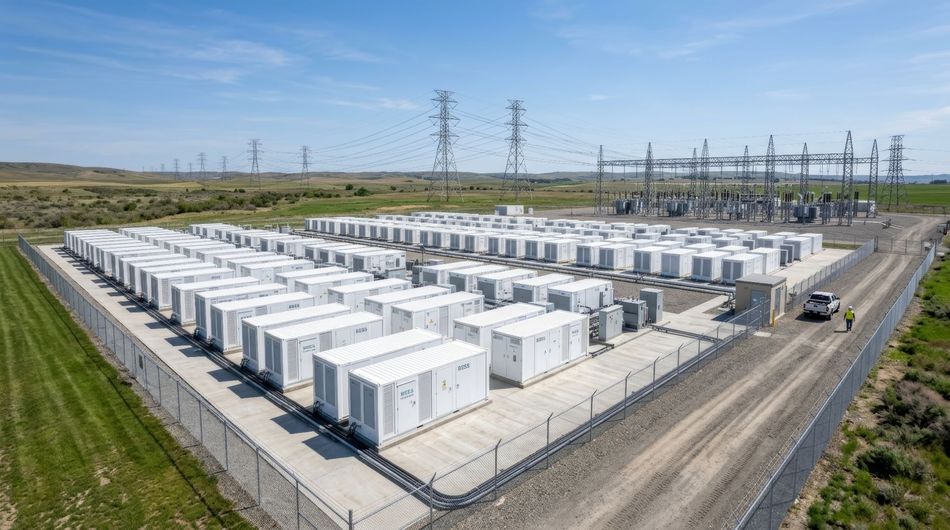
The single biggest drawback of renewable energy sources is their fluctuating and unpredictable energy output. This causes a mismatch between supply and demand that can only be solved by storing the generated energy. BESS integrating renewable energy must offer resistance to UV radiation, moisture, extreme temperatures, and dust, undergo frequent charging and discharging cycles daily.
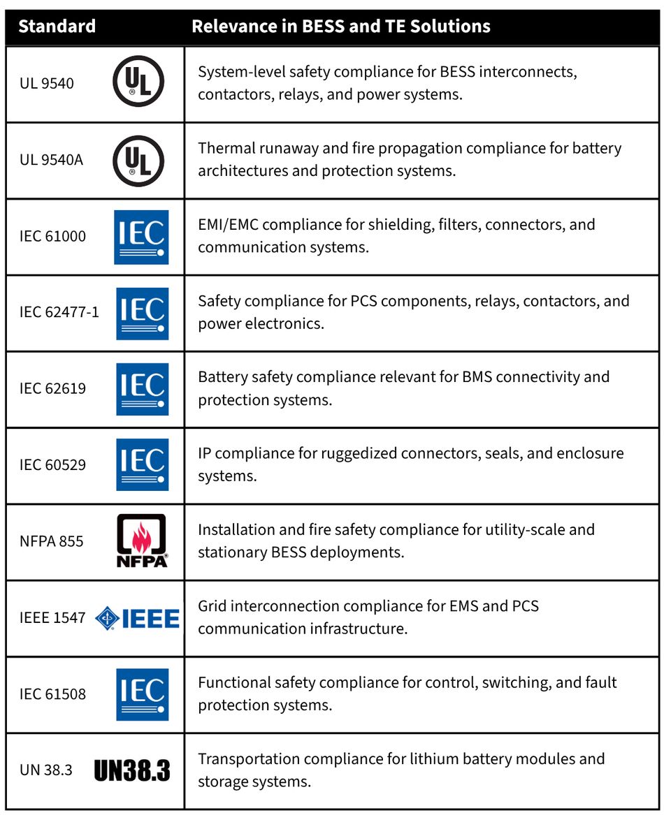
There can be no compromise at this scale of operation, as it has a direct effect on grid stability and triggers contractual penalties for BESS operators under grid service agreements. Along with the performance and longevity constraints, utility-scale BESS must also meet strict EMI and EMC requirements to prevent interfering with nearby protection relays, metering equipment, and communication systems in the grid.
Commercial and Industrial Energy Storage
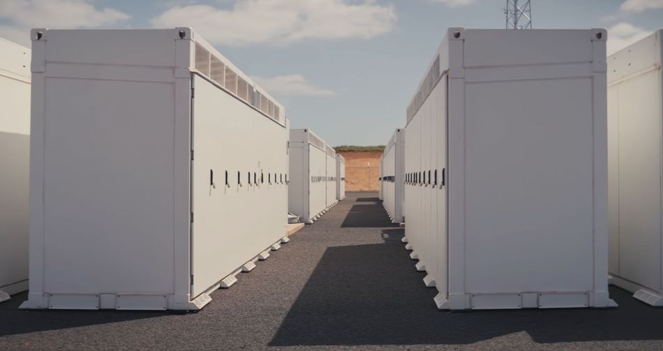
In the commercial and industrial sector, BESS is used to reduce energy costs with time-of-use arbitrage and improve backup power capabilities with storage facilities. Unlike utility-scale BESS deployments, the space here is very limited. The system must be deployed within existing buildings or constrained plants where space, weight, and access are all a luxury.
Reliability of communication is also particularly important in this sector, as the EMS must coordinate with building energy management systems to save energy and ensure continued operation even in case of a power outage.
Electric Vehicle (EV) Charging Infrastructure and Energy Storage
Slow charging and range anxiety are among the top complaints of EV users. To address these concerns, automobile manufacturers are building ultra-fast chargers with ratings touching the megawatt (MW) range. These chargers can charge the EV completely within minutes. It does solve the problems of individual end users but could create a spike in energy demand and destabilize the grid.
To avoid this, BESS are installed to draw energy from the grid when demand is low and store it safely for use when users line up to charge their EVs.

Microgrids and Remote Power Systems
Remote facilities, industrial sites, mining operations, military installations, and critical infrastructure rely on BESS-supported microgrids to reduce dependence on diesel generation. In these setups, BESS is the primary mechanism to balance variable generation from nearby renewable energy with variable loads. What makes the task more difficult is the unavailability of a large grid to support the stability.
As maintenance visits may be infrequent, every layer of BESS must be designed with long-term durability in mind right from the beginning.

Conclusion
It is clear across all the applications that the reliability of BESS is not determined by just the battery packs, controllers, power electronic circuits, filters, or connectivity technologies individually. It is determined by the combined performance of all the components working together under the tough environmental conditions of the deployment.
BESS is no longer an emerging technology. Perfecting BESS design today requires more than just the right battery or power electronics topology; it requires treating each and every electrical interface and communication pathway as a reliability-critical design decision. A weak link at any point has far-reaching financial and operational consequences.
TE Connectivity’s electrification solutions are uniquely positioned to address the connectivity demands across the full stack of BESS. Avnet Abacus brings these technologies to BESS manufacturers with strong sourcing and technical support.