3D Scans And CAD Models For Designing Antenna Mounts On Aircraft For Sar Systems
The German Aerospace Center relies on Creaform metrology services
02 Aug, 2021. 4 minutes read
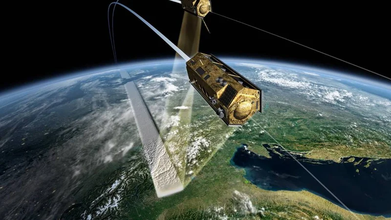
Picture Source: DLR
The Institute of High Frequency Technology and Radar Systems at the German Aerospace Center (DLR) is investigating radar systems and their associated parameters for future satellite missions. To this end, tests are carried out in advance with aircraft-borne systems, which have a high degree of flexibility. For the preliminary tests, the radar systems will be installed on two Dornier Do 228 turboprop aircraft. The antennas required for this purpose will be developed, tested, and integrated into the aircraft system at the institute. For integration, special support structures are needed to mount the antennas on the aircraft fuselage. For this purpose, the exact contour data (CAD models) of various aircraft areas are required for the construction of these support structures or mounts.
As part of a new project for earth observation with two radar satellites in the L-band frequency range, a comparable system is to be installed on two aircraft as a preparatory measure. By observing the earth’s surface with two, simultaneously receiving carrier platforms, extensive new products can be developed. In this instance, products refer to the evaluation of the recorded radar data for specific parameters, models, maps and so on. In addition to the classic 3D terrain model, these include information on vegetation, such as tree cover or deforestation, glacier conditions such as flow velocities and temporary changes in volume, uplift, and subsidence of the ground due to volcanism, earthquakes, or mining, to name just a few applications.
Radar remote sensing is mainly based on the SAR principle (Synthetic Aperture Radar). Here, a very high spatial resolution in the direction of motion is achieved by the movement of the radar system. The principle is distance independent and thus allows high-resolution images of the Earth’s surface from space with very high accuracy. As part of the TanDEM-X mission, DLR operates the German radar satellites TerraSAR-X and TanDEM-X for this purpose. The ongoing investigations are concerned with possible successor systems to the existing constellation of the two X-band satellites. However, at lower frequencies such as L-band, the distances between the satellites become much larger and open up additional challenges in data processing and the algorithms and models used to extract parameters from the raw radar data. The new systems on DLR’s two Dornier research aircraft are used to provide this radar data, long before any potential satellite launch. These are the key areas of DLR’s Institute of High Frequency Technology and Radar Systems.
Task: Creation of 3D scans and CAD models of various aircraft areas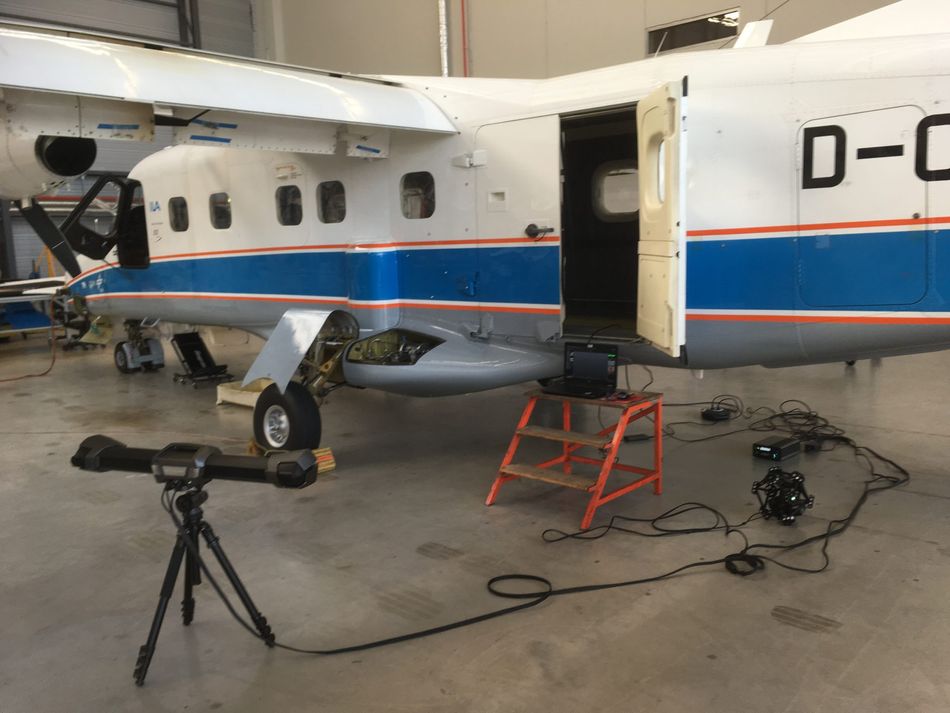
In order to be able to design the available installation space for the antenna mounts on and within the aircraft, highly accurate geometric data is required. In this case, the structures are mounted on the seat rails inside the aircraft and protrude out through a shaft in the floor below the aircraft fuselage. The antenna is mounted there in an aerodynamic fairing. It is mounted so that it can rotate about the vertical axis, within certain limits.
For this project, the shaft and the areas around it – the floor inside the cabin and the area below the fuselage – were of particular interest. To realize the project, accurate CAD models were needed for areas of two aircraft to construct these support structures or mounts. For this purpose, 3D scans first had to be created, from which the CAD models could subsequently be generated. These scans serve as the basis for the construction of the antenna mounts for two Do 228 (DLR-owned research aircraft) in order to be able to carry out SAR recordings in the lower frequency range (L-band) in formation flight. For this purpose, antennas are installed underneath the aircraft fuselage, which radiate and receive laterally at an angle to the ground.
Metrology Equipment and Scanning Systems Used
DLR contacted Creaform’s metrology and engineering service for the surface and volume scans.
Due to the required accuracy, the desired level of detail, and the accessibility of the areas, the Creaform scanning systems were well suited for this project thanks to their portability, speed, and accuracy. The MetraSCAN 3D and HandySCAN 3D scanners and the MaxSHOT 3D photogrammetry system were used. Two aircraft were scanned in DLR Research Flight Department at the Oberpfaffenhofen and Braunschweig sites.
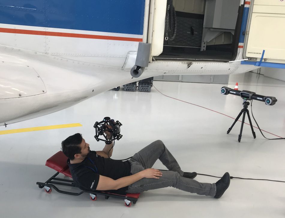
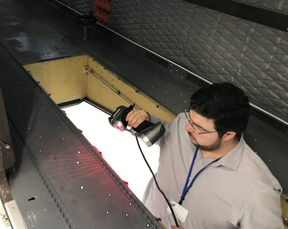
The entire position model of the aircraft (interior and exterior) was recorded using MaxSHOT 3D. This photogrammetry system enabled the accuracy of the overall measurement to be increased and the dimensions of the exterior to be combined with those of the interior. The MetraSCAN 3D scanner was used to capture the relevant exterior areas of the aircraft such as the fuselage, while the HandySCAN 3D scanner was used to capture details and hard-to-reach areas inside the aircraft, such as the floor hatch.
Post-processing of the scans was done using the software VXmodel: First, the scan was cleaned up, aligned, and unnecessary surfaces were removed. Subsequently, the scan was prepared for reverse engineering in CATIA. For each aircraft, on-site measurements took about 4-5 hours (including set-up and tear-down), post-processing about 2-3 hours, and reverse engineering almost two weeks.
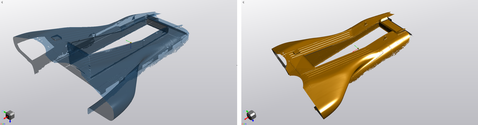
Image below: Scan and post-constructed CAD model of the floor hatch of a scanned aircraft
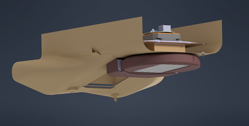
A first sketch of the construction of one of the two antenna supports, integrated into the existing 3D scan of the aircraft cabin, is shown in the following figure. In the data, reference can be made to individual rivet positions, the seat rails in the interior, or joints of the sheet metal on the aircraft fuselage.
Conclusion and ROI
Dipl.-Ing. Markus Limbach of the DLR Institute of High Frequency Technology and Radar Systems is very satisfied: “The hardware we used, together with Creaform’s extensive data processing capabilities and expertise, seemed optimal for our task. Less positive experiences have shown that not all providers can offer the same standard of quality.”
“In terms of the ROI we have generated by using Creaform’s metrology team, we expect to save about 6-8 weeks in terms of labor time. That is incredibly satisfying.”