3D Copper: The Missing Link for Accurate Thermal Analysis
Discover why missing 3D copper data creates thermal blind spots for mechanical engineers—and how accurate ECAD-MCAD exchange prevents costly late-stage failures.
20 Nov, 2025. 4 minutes read
Thermal failure is arguably the most common and expensive surprise in the electronics product lifecycle. When an overheating issue is discovered late—usually during physical prototyping or system-level testing—the subsequent design respin can add weeks to the schedule and balloon procurement costs. It’s a moment that confirms when electrical, mechanical, and supply chain disciplines are misaligned.
Modern product development demands that core, often late-stage, stakeholders like procurement and manufacturing must have a seat at the design table from the start. This is only possible if they are equipped with data that allows for early, high-fidelity validation.
For the mechanical engineer responsible for thermal management, that critical, missing piece of data is the 3D copper geometry of the printed circuit board (PCB).
We often talk generally about the importance of ECAD-MCAD collaboration, without explaining the specific reasons why the advanced transfer of copper data is essential to the mechanical engineer’s job—and why its absence poses a direct and costly risk to new product introduction (NPI).
The Mechanical Engineer’s Thermal Blind Spot
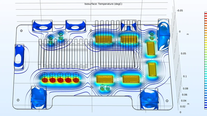
When mechanical engineers begin a thermal simulation, they are attempting to solve a conjugate heat transfer problem. They must predict how heat generated by active components (like CPUs, GPUs, or power converters) will spread through the PCB and into the enclosure or cooling solution.
The most critical pathway for heat dissipation on a modern PCB is the copper itself. Copper has a thermal conductivity of roughly 385 W/mK, vastly superior to the FR4 dielectric material, which is around 0.3 W/mK. Simply put: copper is the heat sink.
In traditional ECAD-MCAD data exchange, the workflow fails because static, generic file formats (like IDF, IDX, or simple STEP models) transfer only partial data, which causes issues in the communication between electrical and mechanical teams. This miscommunication between teams leads to:
Inaccurate Data Handoff: During this traditional file exchange, CAD data can lose its native definition and accuracy. This compromises critical clearance and fit checks and often happens without being flagged.
Copper Data Loss: The detailed copper features—the complex networks of power and ground planes, thermal relief voids, and signal traces—are either excluded entirely or sent as abstract 2D graphical data that lacks the geometric intelligence needed for mechanical simulation software (FEA/CFD).
This leaves the mechanical engineer with a thermal blind spot. They have a 3D board shape, but the thermal engine is effectively running on a two-dimensional approximation.
The Costly Manual Rebuild: Approximation vs. Accuracy
Faced with this incomplete data, the mechanical engineer is forced into a costly and time-consuming workaround that directly compromises the quality of the thermal analysis.
The Manual Workaround
Engineers must manually recreate the copper geometry or, more commonly, resort to simplification or approximation methods:
Simplification: They might model the entire layer as a block of homogeneous material, using an "effective" thermal conductivity based on an estimated copper percentage (e.g., assuming 60% copper coverage).
Approximation: They may calculate orthotropic material properties for the stackup, assigning different conductivity values for the X/Y (horizontal) and Z (vertical) directions.
The Dual Financial Risk
This reliance on approximation introduces high uncertainty and creates two significant risks that directly impact procurement and manufacturing:
Risk A: Catastrophic Failure (Underestimation)
If the engineer overestimates the actual copper coverage or connectivity, their simulation predicts better heat spreading than will actually occur.
Result: The final enclosure design or heatsink solution is under-engineered. The product passes mechanical clearance checks but fails thermal testing.
Business Impact: This forces an immediate, mandatory respin. Procurement must halt orders and source new, likely more expensive, thermal management solutions (larger fans, different heat sink materials, or even a thicker PCB stackup), leading to budget overruns and delayed market entry. The integrity of the manufacturing process is compromised by a design flaw.
Risk B: Wasteful Over-Engineering (Overestimation)
If the engineer is overly conservative and underestimates the copper coverage, they will overcompensate in their mechanical design.
Result: They specify oversized fans, unnecessarily large heatsinks, or use high-cost thermal interface materials (TIMs) that are not actually required.
Business Impact: Procurement is forced to buy components that are too expensive, too large, or too heavy, bloating the Bill of Materials (BOM) and reducing profitability. The lack of accurate copper data leads directly to unnecessary material cost.
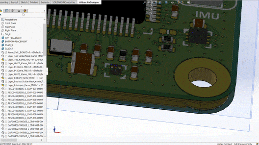
The Solution: Intelligent, Native 3D Copper Transfer
The modern ECAD-MCAD codesign workflow available in Altium Agile Teams is designed to eliminate this blind spot. Instead of relying on static file translations, this platform facilitates the transfer of the actual, native 3D copper geometry as intelligent CAD data.
What this means for the mechanical engineer and the business:
High-Fidelity Simulation: Engineers run their FEA/CFD simulations (whether for thermal, vibration, or structural stress) using the exact copper features designed by the electrical team. This removes all assumptions and ensures the results are grounded in the final, manufacturable design.
Accurate Interlayer Modeling: The system transfers the geometry of all interlayer copper, including the copper barrels of plated holes and vias. This is a critical factor for Z-axis thermal and structural analysis, as plated holes are the primary high-conductivity pathway for vertical heat dissipation into cooling solutions.
Real-Time Validation: The entire team can validate the thermal design concurrently, catching potential hot spots while the copper layout is still flexible. If the team finds an issue, they can propose a specific, measurable change (e.g., widen a critical trace, adjust a plane shape) that is verified in the mechanical environment before they push it back to ECAD.
Procurement Confidence: With a high-fidelity thermal analysis complete, the engineer can confidently sign off on the thermal management solution and enclosure design. Procurement can then order materials with the assurance that the specifications are optimized—not under-engineered (leading to failure) nor over-engineered (leading to cost overruns).
Giving the mechanical engineer access to advanced copper geometry through an MCAD codesigner isn't just a technical upgrade; it's a strategic move that delivers accuracy to the thermal model, confidence to the procurement process, and reliability to the manufacturing outcome.
This is the foundation of modern, collaborative, multidisciplinary hardware development. It instantly synchronizes electrical, mechanical, procurement, and manufacturing within a single, traceable environment. Altium Agile Teams helps those experts collaborate–in one shared workspace–to eliminate thermal risks before they can cause costly respins. To see how this solution empowers your collaborative product development, sign up for a free trial of Altium Agile Teams today.