Meshing in FEA, CFD & Manufacturing
Accurate mesh generation is a critical step of every engineering design workflow that involves FE analyses, CFD simulations, or Additive Manufacturing.
23 Jun, 2021. 8 minutes read
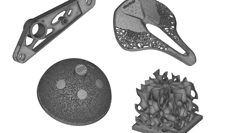
A selection of meshes of parts with intricate lattices, gyroid structures, and topology optimized shape generated in nTopology.
This article was first published on
ntopology.comAccurate mesh generation is a critical step of every engineering design workflow that involves FE analyses, CFD simulations, or Additive Manufacturing. Here, we give you practical tips and design considerations for meshing parts with complex geometries, like lattice structures, using nTopology’s powerful meshing capabilities.
Meshing complex geometry is one of the most critical factors for simulation and manufacturing. However, there is a delicate balance between generating an accurate mesh and creating a file that is too large for practical application.
In this blog post, we share practical tips to generate robust meshes for parts with complex geometries. Follow the links to jump to the relevant section:
- Introduction to meshing
- Design considerations for meshing
- The meshing process
- Practical meshing tips & rules of thumb
What is Meshing?
Meshing is the process of dividing a 3D model into thousands of elements to properly define its shape — the more detailed the mesh, the better the approximation. Meshes are used to run engineering simulations, communicate manufacturing data, or for rendering.
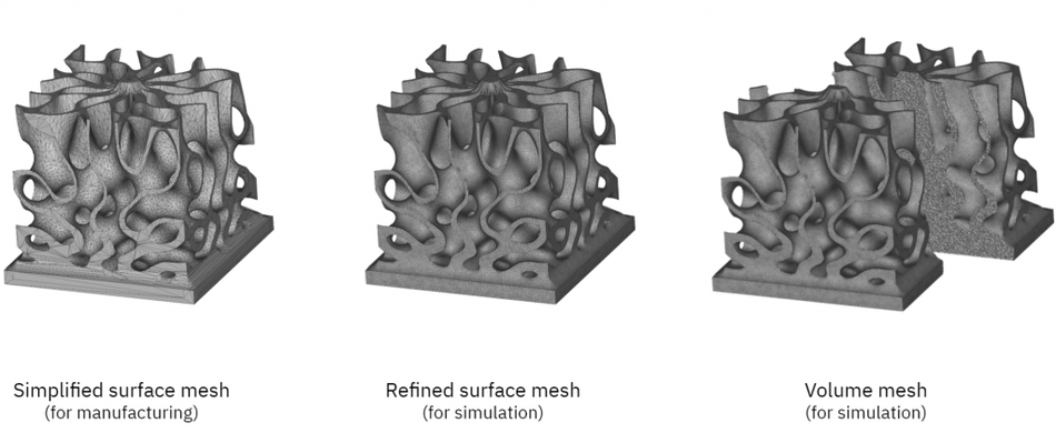
There are two main types of meshes: surface meshes and volume meshes:
- Surface meshes use two-dimensional elements — typically triangles or quads — to approximate the outer surface of a 3D body. Surface meshes are used in manufacturing or rendering applications.
- Volume meshes, also known as solid meshes, use three-dimensional elements — typically tetrahedrons or hexahedrons — to define both the surface and interior structure. Surface meshes can be converted into volume meshes to run FE or CFD simulations.
Why is meshing important in FEA and CFD?
Meshing is integral to computational simulation techniques, like the finite element method (FEM) and computational fluid dynamics (CFD). Simply put, FEA or CFD simulations are not possible without a mesh. Meshes discretize a continuous geometric space into predictably shaped and mathematically defined elements. This discretization enables computers to numerically solve the underlying governing equations and simulate the physical effects. The mesh quality influences the accuracy, convergence, and speed of the simulation process.
Why is meshing important in manufacturing?
Meshes are used to communicate manufacturing data. Meshes are often considered a necessary evil in manufacturing. For example, the STL file format is a mesh with triangular elements that describe the surface of a solid body. Today, STLs are the predominant file format for sharing part data for additive manufacturing. However, many have criticized this file format because it falls short in conveying other essential manufacturing information. In addition, it introduces an unnecessary data conversion step that can potentially reduce accuracy.
Design Considerations for Meshing Complex Parts
A high-quality mesh needs to be:
- Error-free (i.e. manifold, oriented, and non-self-intersecting)
- Detailed enough to produce accurate simulation results and ensure manufacturing tolerances.
The best meshing parameters depend on the intended application. For example, a very fine mesh captures more accurately the 3D geometry, allowing for higher fidelity simulations. However, it also produces a larger file size; as a rule of thumb, halving the grid size increases its file size and the time it takes to compute by a factor of 4x to 8x.
There is no need to spend additional computational resources when the same result can be achieved with a simpler mesh.
When meshing the user must balance computational resources and the intended use of the geometry. This trade-off is especially relevant when generating meshes for parts with complex geometry, such as lattices and organic shapes. These geometries require more elements to capture the intricate part features and curved surfaces accurately.
Meshing in nTopology
Generating a mesh in nTopology is configurable and (potentially) fully automatic. nTopology offers a range of configurable meshing tools that enable you to build reusable meshing processes and modify them to your application. Here we will go through some of the new meshing capabilities that were introduced recently to the software.
What is the Meshing Process?
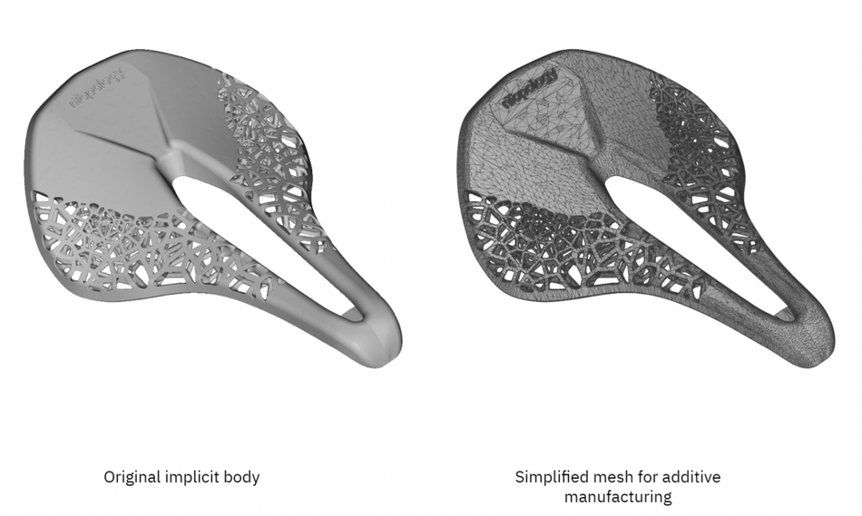
The mesh generation process begins with creating a surface mesh from an implicit body. The surface mesh can then be post-processed, remeshed, coarsened, exported as an STL or 3MF for manufacturing, or converted into a volume mesh for simulation.
There are currently two main methods to discretize a 3D body into a mesh in nTopology:
- Using the Mesh from Implicit Body block — the “quick” approach
- Using the new Mesh from Implicit Body by Voxels block — the new “robust” approach
Note: At the time of writing, the Mesh from Implicit Body by Voxels block is in beta. Beta blocks are fully functional but may be subject to change before their full release.
The algorithms that these two blocks use to discretize the geometry are different, making them more suitable for different applications. Let’s take a closer look at these mesh generation blocks.
Remember that every meshing operation is essentially a discretization operation that approximates the intended 3D geometry. The goal is to fit mathematically-well-defined mesh elements to a 3D body while minimizing the overall error and while making sure that all elements connect properly to each other.
Mesh from Implicit Body
The algorithm of the Mesh from Implicit Body block attempts to fit a surface mesh of triangular element type directly to the surface of the implicit body. In technical terms, the Mesh from Implicit Body block uses a dual contouring algorithm.
Benefits: This block is fast, enables you to control the uniformity of the mesh, and can generate meshes with sharp edges.
Limitations: For part geometries with varying curvature (like parts with a gyroid lattice), the produced mesh may have self-intersecting triangles or be non-manifold. These errors may be acceptable for manufacturing applications, but the mesh needs to be repaired before it is suitable for simulation.
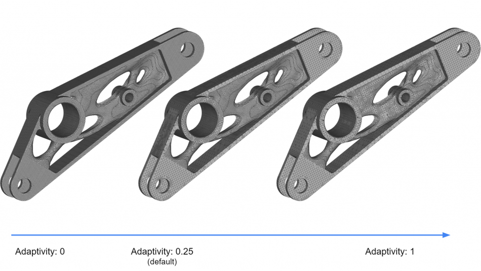
Recommended settings: As a starting point, it is recommended to use a feature size smaller or equal to 0.6x to 1.0x the thickness of the smallest feature and adaptivity of 0 for a uniform mesh or 1 for mesh with fewer triangles.
Mesh from Implicit Body by Voxels
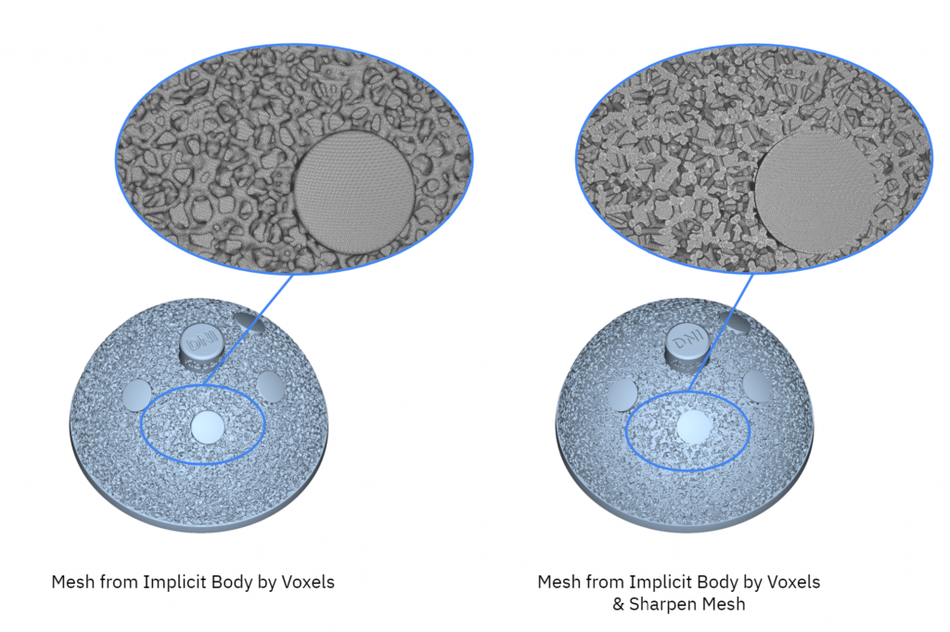
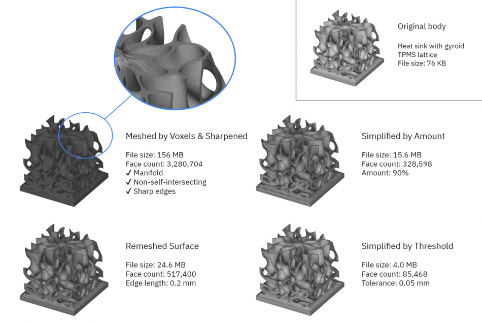
The Mesh from Implicit Body by Voxels introduces an intermediate voxelization step to create a robust meshing process for shapes with complex geometries. The algorithm first approximates the volume of the 3D body by fitting a voxel grid at the specified tolerance level. Then it generates a surface mesh based on this voxel grid.
Benefits: The Mesh from Implicit Body by Voxels is exceptionally robust and produces error-proof meshes even for the most complex geometries. It also introduces the concept of tolerances in mesh generation, which is a more intuitive way to select meshing parameters.
Limitations: The output of this block tends to remove sharp edges. This is usually acceptable for parts with no sharp edges or for manufacturing but can cause inaccurate simulation results — for example, while running an analysis of geometry with sharp features.
To overcome this limitation, we can either reduce the tolerance value (increasing computation time) or we can use the Sharpen Mesh block to restore sharp edges. This block runs an intelligent reconstruction algorithm that identifies the sharp edges in the original model and adjusts the position of the mesh nodes and vertices accordingly to capture these edges.
Recommended settings: As a starting point, it is recommended to use a tolerance equal to 0.5x the thickness of the smallest feature. This value will typically exceed the accuracy of most additive manufacturing processes. If you are planning to sharpen the mesh, avoid the simplify and remeshing options of this block. When using the Sharpen Mesh block, a single iteration will usually produce good results.
Mesh post-processing

Apart from these two core meshing capabilities blocks, in nTopology you will find many meshing tools that can help you better prepare for downstream operations. Here are some of the most helpful mesh post-processing blocks.
- Remesh Surface: The mesh generation blocks in nTopology do not produce mesh with an exact element size. This block can be used to create a mesh with explicitly chosen properties using triangle or quad elements. Remeshing comes in handy when you need to control the mesh properties and prepare them for simulation.
- Simplify mesh by Threshold: This is an easy way to reduce the file size of a mesh for manufacturing. This block will create the mesh with the least amount of faces. A good starting point for the threshold is 1/4 to 1/8 of the manufacturing tolerance.
- Simplify mesh by Amount: This block generates a mesh that is smaller than the original based on the specified amount. For example, a value of 0.9 will create a mesh with 90% fewer faces, and as a result 90% smaller file size.
- Volume Mesh: This block converts a surface mesh into a volume mesh. This is a necessary step before FEA or CFD simulations. We recommend using the Remesh Surface block using a triangle mesh before converting it into a solid tetrahedral mesh.
Practical Meshing Tips & Rules of Thumb
Creating a high-quality mesh is not a straightforward process. The optimal parameters depend on object geometry and the intended use. However, the following tips will put you in the right direction.
Preparing meshes for 3D printing
The optimal mesh size depends on the minimum feature dimension and the achievable tolerance of your manufacturing process.
Most additive manufacturing systems produce parts with a feature tolerance of ± 0.1 to 0.2%. For this reason, a tolerance of 0.2 mm (or 1/2 the thickness of the smallest feature size) for the Mesh from Implicit Body by Voxels block is a good starting point. This value typically produces a good trade-off between accuracy and file size.
The Simplify Mesh by Threshold is particularly useful for minimizing the file size for manufacturing. It is recommended to use a threshold value that is within your manufacturing tolerance
Preparing meshes for simulation
The finer the mesh, the more accurate results the simulation will produce and the longer it will take to complete.
Ideally, we recommend running a mesh convergence study to identify the optimal mesh size. In a mesh convergence study, we repeat the simulation with progressively finer meshes until there is no significant difference in the response. However, this process is not always practical, as meshing typically consumes a significant portion of time. We can use nTopology’s design automation capabilities to accelerate this process.
The following setting for the Remesh Surface block is a good starting point for meshing any complex geometry before performing an FE or CFD simulation:
Use a Growth rate between 1.2 to 2.0 — this is the industry standard for FEA and CFD. The growth rate dictates how smooth the transition between the finer and coarser areas of the mesh allows us to capture edge effects better.
Use an Edge length that is best suited for the simulation that you are performing:
Thermal FE: An edge length equal to the wall thickness is sufficient.
Structural FE for deflection analysis: Use an edge length ≤ 1/3 of the wall thickness.
Structural FE for stress analysis: Use an edge length ≤ 1/5 of the circumference of the smallest fillet, hole, or other transition to capture edge effects.
CFD for fluid analysis: Use an edge length that is ≤ 1/7 of the wall thickness to properly simulate fluid flow.
Key takeaways
Accurate mesh generation is a critical step of every engineering design workflow that involves FE analyses, CFD simulations, or Additive Manufacturing. With nTopology’s recent meshing enhancements, nTop users can generate high-quality meshes using automated workflows. Using this article’s tips and nTopology’s robust and automated meshing tools should set you on the right path.
Here’s what you need to remember:
- An overly refined mesh unnecessarily increases file size and wastes computational resources and time. Find a balance between accuracy and speed.
- Use the Mesh from Implicit Body by Voxels and Sharpen Mesh blocks for robust meshing of even the most complex organic shape or lattices. Choose the Mesh from Implicit Body for quick mesh generation of simpler parts.
- Coarsen the mesh to prepare it for additive manufacturing or adjust the mesh parameters using Remesh Surface to prepare it for simulation.
This article was first published on the nTopology blog.