Coaxial Cable Connectors: Types, Impedance, Frequency, and Selection Guide
Explore the most common types of coaxial cable connectors, their specifications, applications and key selection criteria for ensuring reliable, shielded and impedance-matched connections across electronic equipment.

18 Nov, 2026. 8 minutes read
This article was first published on
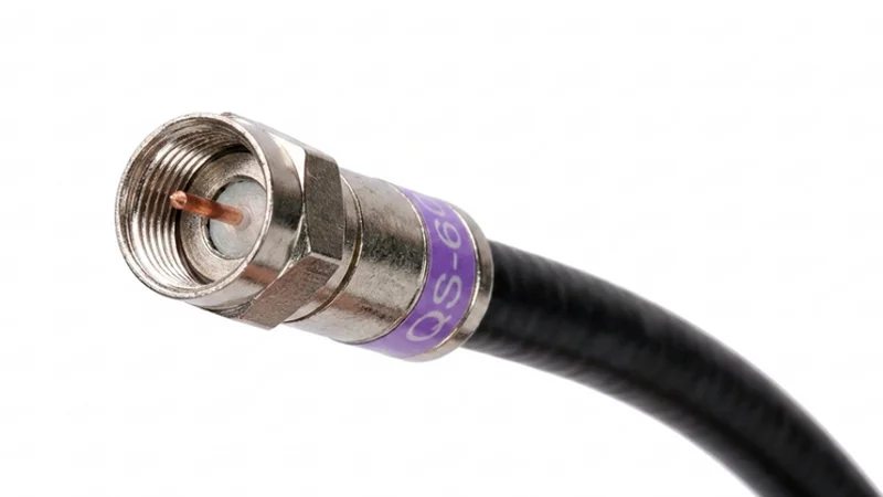
www.unikeyic.comCoaxial cable connectors electronic equipment, antennas, instruments or other cable assemblies while preserving the cable’s shielding and controlled-impedance signal path. Coaxial cable connectors are used for many fields, including broadcasting, telecommunications, military and consumer electronics. In this article, this article explains the most common types of coaxial connectors, their specifications and how to select the proper coaxial connector for your equipment.
What Is a Coaxial Cable Connector?
A coaxial cable connector is a specialized interface used to connect a coaxial cable to equipment, another cable, an antenna, or a test instrument. A coaxial cable typically consists of a center conductor, a dielectric insulator, an outer shield such as a braid or foil, and an external jacket. This concentric construction helps maintain the cable’s characteristic impedance, reduce signal leakage, and minimize the effects of external electromagnetic interference.
Proper selection of coaxial cable connectors ensures reliable signal transmission.
Crucial Specifications: Impedance and Frequency
Before examining specific connector types, it is essential to understand two foundational specifications:
Impedance
The typical coaxial cable connector has an impedance of either 50-ohm or 75-ohm. Both 50-ohm and 75-ohm versions are available. They should not be mixed in the same controlled-impedance signal path. Impedance mismatch can cause increased signal reflections, lower return loss, signal distortion, and reduced power transfer.
(a) 50-ohm connectors are used primarily in wireless communications, data transmission, and radio frequency applications. They are commonly used for satellite communication, wireless networks, and other important telecommunication equipment.
(b) 75-ohm connectors are usually used for video signals including cable television, satellite systems and broadband internet.
Critical rule: Impedance of coaxial connector should always be matched to the cable and the equipment.
Frequency
The frequency of a coaxial connector depends entirely on the type of connector and can be 40 GHz or higher. Standard BNC connectors are commonly used around DC to 4 GHz. Some high-frequency broadcast-oriented variants, such as HD-BNC or Mini-BNC designs, may support higher-frequency or 12G-SDI applications depending on the specific manufacturer and assembly.
These factors affect the performance of the connectors at high frequencies: Insertion loss, return loss, VSWR, impedance mismatch, physical discontinuities in the connector and the cable assembly.
Common Types of Coaxial Connectors
BNC (Bayonet Neill–Concelman)
The BNC connector is one of the most commonly used and recognized types of coaxial connectors. It was originally designed for military radio equipment in the 1940s. It features a bayonet locking mechanism that allows quick connection and disconnection and disconnect the connector with just a quarter turn.
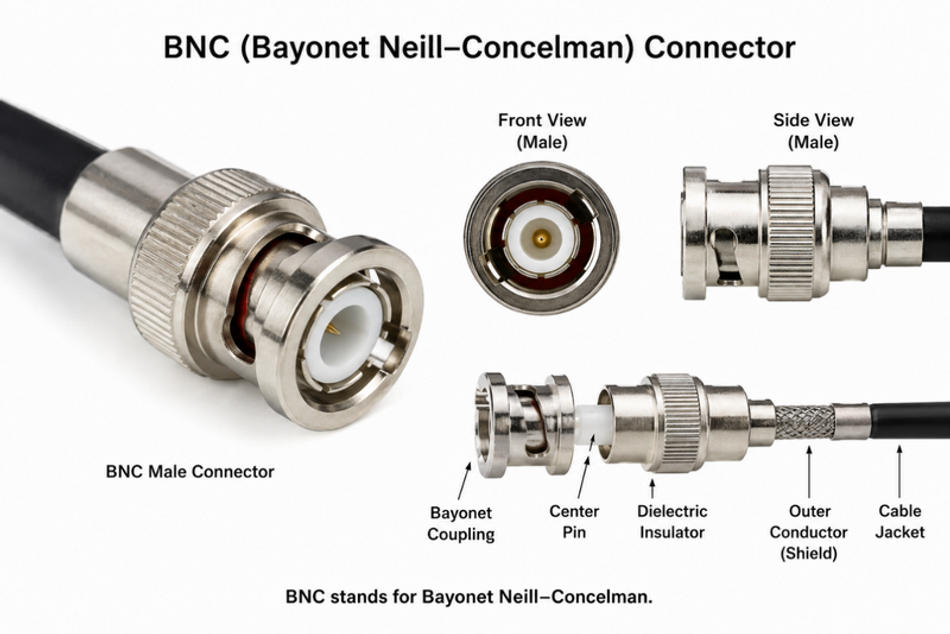
Impedance: 50Ω and 75Ω versions of BNC connector are commonly available (93Ω versions also exist but they are rare).
Frequency: Typically, standard 50-ohm BNC connectors are used from DC to ~4 GHz. The 75-ohm BNC versions are usually employed for video and broadcast systems, and the frequency range will vary from connector to connector, cable to cable and assembly to assembly.
Applications: Oscilloscopes, Signal generators, RF test systems, broadcast video equipment, Avionics and other military or industrial systems.
Coupling Type: Bayonet (twist-to-lock).
Advantages: Quick connect/disconnect, widely available in the market and relatively inexpensive than other types.
Limitations: Standard BNC connectors are commonly rated to around 4 GHz, so they may not be suitable for higher-frequency applications. However, specialized high-frequency BNC variants are available with higher frequency ratings, depending on the connector design and manufacturer.
F-Type Connector
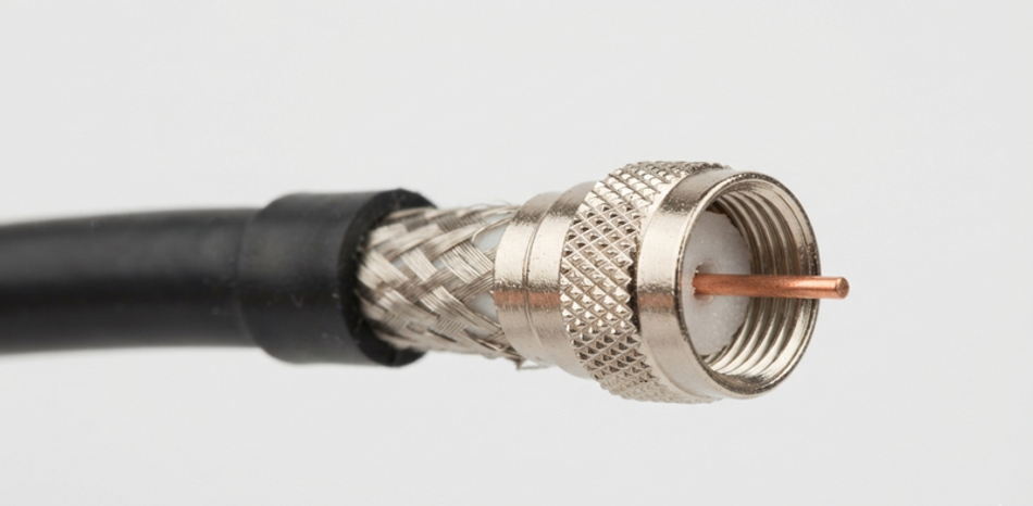
An F-type connector is a standard threaded coaxial connector which is widely used for television, satellite television and cable modems. It has a 75 Ω impedance for frequencies up to 3 GHz. F-type connector is a simple-to-install connector and it uses a threaded mechanism for coupling with RG6 or RG59 cables.
Impedance: 75Ω
Frequency: DC (0 Hz) to 3 GHz.
Applications: Cable television (CATV), satellite TV receivers, broadband cable modems, set-top boxes.
Advantages: Low cost, simple installation, easily available for domestic and commercial use.
N-Type Connector
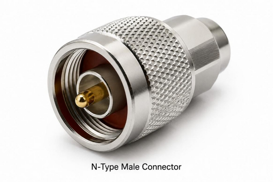
The N-Type connector is a rugged, threaded RF coaxial connector commonly used in 50Ω systems, although 75Ω versions are also available for specific applications. It is widely used in wireless communications, cellular infrastructure, antennas, microwave systems, satellite equipment, and broadcast applications. Its threaded coupling provides a secure mechanical connection, and weatherproof versions are available for outdoor installations.
Impedance: Commonly 50Ω but 75Ω versions are also available.
Frequency: Standard N-Type connectors commonly operate up to 11 GHz, while extended-range versions can operate up to 18 GHz.
Applications: Wi-Fi antennas, Satellite dishes, cellular base stations and networks, radar systems, WLAN and broadcast equipment.
Coupling: Threaded.
Advantages: N-type connectors have excellent high-power handling capabilities, good mechanical stability, and good shielding effectiveness. Actual RF shielding performance depends on the connector design, frequency range, and manufacturer specifications. The improvement in mechanical stability and vibration resistance comes from their threaded coupling; however, RF loss also dependent on the connector type, cable type, termination quality, and installation condition.
SMA (SubMiniature version A)
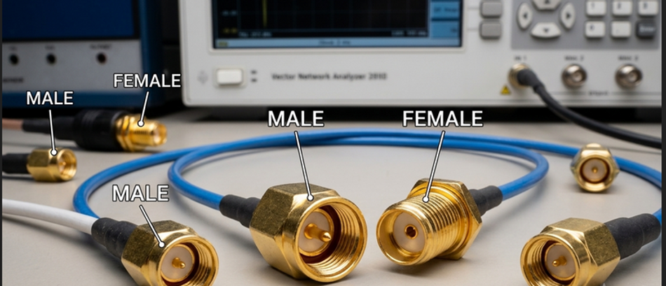
The SMA connector is a precision threaded connector that serves as the workhorse for high-frequency applications like microwave systems, Wi-Fi routers, 4G/5G antennas and high-frequency test equipment. It ensures reliable and low loss signal transmission and is one of the most commonly used RF connectors worldwide.
Impedance: 50Ω is the most commonly used.
Frequency: It supports up to 18 GHz in standard configurations.
Applications: Microwave systems, Wi-Fi and Bluetooth antennas, GPS trackers, mobile telephone antennas, telecommunications and test equipment such as oscilloscope, spectrum analyzers and signal generators.
Coupling: Threaded screw-on mechanism with a 1/4-36 thread that ensures a secure, vibration-proof connection for compact RF systems.
Advantages: Compact size, secure threaded coupling, and good high-frequency performance. Some SMA versions are available with sealing or weather-resistant features for specific outdoor applications. RF performance, power handling, environmental protection, and maximum frequency depend on the specific SMA connector design.
TNC (Threaded Neill–Concelman)
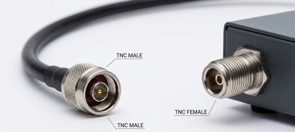
A TNC (Threaded Neill–Concelman) connector is a threaded connector similar to BNC. It has a 50 ohm impedance and offers a much more stable and reliable connection that can support frequencies up to 11 GHz.
Impedance: The standard for RF and microwave systems is 50Ω. There are also variants of 75Ω for certain video/telecom applications.
Frequency: It supports up to 11 GHz in standard configurations (and up to 18 GHz in high-performance precision variants).
Applications: It is used in aerospace, military communications, cellular base stations, Wi-Fi antennas, radar systems, and high-vibration automotive environments.
Coupling: Threaded 7/16-28 UNEF interface, providing a secure mechanical connection with good resistance to vibration.
Advantages: Secure threaded coupling provides good resistance to vibration and mechanical movement. TNC connectors can provide good RF performance at microwave frequencies and are available in designs suitable for demanding environments. Performance and frequency range depend on the specific connector design.
Consumer A/V Coaxial-Style Connectors (RCA)
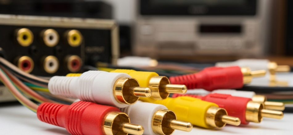
RCA connectors are found on older audio and video equipment, using a single center pin surrounded by a metal ring for grounding. They are used to transmit audio and video signals between devices. Their plugs correspond to specific jacks: yellow for video, white or black for the left audio channel and red for the right audio channel.
RCA connectors are widely used in consumer audio and composite video equipment, but they are not precision controlled-impedance RF connectors. They should not be treated as substitutes for BNC, SMA, N-Type, TNC, or other RF coaxial connectors in high-frequency systems.
7/16 DIN
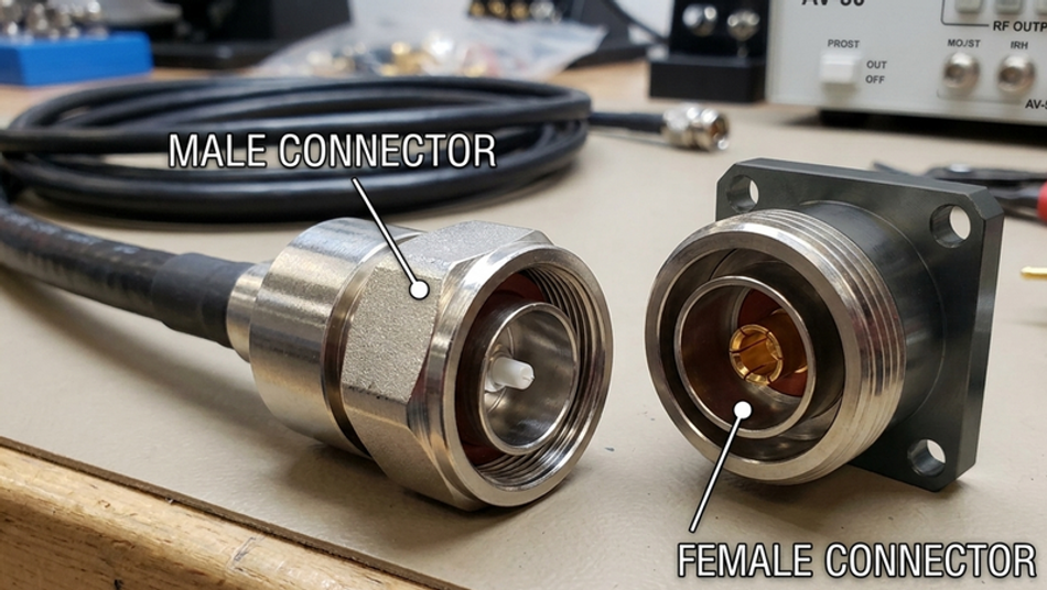
A 7/16 DIN connector is a heavy-duty, high-power RF coaxial connector designed for demanding communication and antenna applications. The 7/16 designation refers to nominal interface dimensions specified by the applicable connector standard, with approximately 7 mm associated with the inner conductor and 16 mm with the mating interface of the outer conductor. The connector is widely used where high-power handling, low passive intermodulation (PIM), and mechanical durability are important.
Impedance: 7/16 DIN connectors are designed for high-power RF applications and provide good electrical performance, low insertion loss, and low passive intermodulation (PIM) when properly designed and installed.
Frequency: Frequency: Typically DC to 7.5 GHz, depending on the specific connector and cable assembly.
Applications: Cellular network infrastructure, antenna systems with multiple transmitters, defense applications, and high-power RF sites.
Coupling: Threaded M29 x 1.5 screw-on mechanism that uses a large hex nut to provide a heavy-duty, vibration-proof, weather-resistant connection when the connector is properly sealed and installed according to the manufacturer's specifications.
Advantages: High power handling, excellent PIM performance, and availability of weather-resistant versions for outdoor installations. Increasingly used in new and high-power installations.
Additional Connector Types
Connector | Coupling | Impedance | Frequency | Typical use |
SMB | Snap-on | 50Ω / 75Ω (Variant dependent) | DC-4 GHz | GPS receivers, automotive telematics, and wireless boards. |
MCX | Snap-on | 50Ω / 75Ω
| DC-6 GHz | GPS tracking, mobile devices, and internal wireless hardware |
MMCX | Snap-on | 50Ω | DC-6 GHz | Ultra-miniature applications |
QMA | Quick-lock | 50Ω | Up to 18 GHz | Fast RF connections |
Gender, Polarity, Materials, and Plating
Coaxial connectors are commonly available as male and female interfaces. A male connector typically has a protruding center contact, while a female connector has a mating socket or receptacle.
Mounting styles such as panel-mount, bulkhead, and flush-mount describe how the connector is installed and do not necessarily indicate its gender. Some specialized connector interfaces may use genderless or hermaphroditic designs.
Reverse-polarity connectors, like RP-SMA, reverse the center contact gender, but do not affect the polarity of the RF signal. In particular, they have been utilized in certain wireless applications to accommodate the specific antenna-connector needs of the products, market and applicable regulations.
Connector Materials and Plating
Mechanical strength, corrosion resistance, conductivity, spring performance and cost are the factors considered when choosing the type of connector materials. Brass is often used for connector bodies because it conducts and is easily machined. Spring contacts are typically made of beryllium copper or phosphor bronze to provide contact force over multiple mating cycles. Where durability and resistance to corrosion are more important, stainless steel is used, but its conductivity is lower than the copper alloys. Center contacts are often gold plated to help ensure low level signal contact resistance and to prevent oxidation. Silver is conductive and can be used in some RF and power applications but it can tarnish in sulfate containing environments. Nickel is frequently applied as a surface layer of corrosion protection or as an underplating, but it is not selected for its conducting properties.
How to Select the Proper Coaxial Connector
To select proper coaxial connector, always consider these factors:
- Impedance: Match the connector to your cable and equipment. A 50Ω connector is used for radio frequency (RF) signals, two-way radios and antennas. A 75Ω connector is typically used for video/CATV.
- Frequency range: Select a connector which is rated for your system and operating frequencies.
- Environmental conditions: For outdoor or harsh environments, choose weatherproof connectors like N-type or 7/16 DIN.
- Connection frequency: Use Bayonet (BNC) and Snap-on connectors when connectors are removed/installed often. Threaded connectors like SMA, N-type and TNC provide more reliable connections for permanent connections or the connections which are subject to vibration.
- Cable compatibility: Different cables require different connector sizes and termination methods so please check your cable's label (e.g., RG6, RG59, or RG11).
- Space constraints: For close spaces, consider miniature connectors like SMA, MCX, or MMCX.
- Power handling: High-power applications may require larger connectors like 7/16 DIN.
- Return loss / VSWR: Check the connector's rated VSWR and return loss for your frequency range.
- Termination method: Confirm whether crimp, solder, compression, or clamp termination matches your cable and tooling.
- PIM performance: For cellular infrastructure, verify passive intermodulation (PIM) rating.
- IP rating and mating cycles: Check sealing rating for outdoor use and the connector's rated number of mating cycles.
- Torque requirement: SMA, N-Type, and 7/16 DIN connectors require correct torque during installation for reliable performance.
The table below summarizes the key selection factors:
Selection factor | What to verify | Why it matters |
Impedance | 50-ohm or 75-ohm across cable, connector, and equipment | Prevents reflections and return loss |
Frequency | Rated frequency of connector and cable assembly | Avoids excessive loss at high frequency |
Cable compatibility | Cable group, OD, dielectric, center conductor | Ensures correct termination |
RF performance | VSWR, return loss, insertion loss | Determines signal integrity |
Environment | IP rating, corrosion, temperature, vibration | Ensures reliability |
Power / PIM | Power rating, voltage, PIM | Critical for high-power and cellular systems |
Mechanical interface | Coupling, gender, polarity, mount style | Prevents mismating and installation issues |
Conclusion
Coaxial cable connectors are controlled-impedance RF interfaces, not simple mechanical adapters. The right connector should match the cable, equipment, impedance, frequency range, RF performance requirements, termination method, and installation environment. For low-frequency video or CATV systems, 75-ohm connectors such as F-Type or 75-ohm BNC may be appropriate. For RF, wireless, test, microwave, or outdoor antenna systems, 50-ohm connectors such as BNC, TNC, SMA, N-Type, or 7/16 DIN may be used depending on frequency, power, vibration, sealing, and space requirements. Final selection should always be verified against the manufacturer’s datasheet, cable assembly specifications, and actual system requirements.