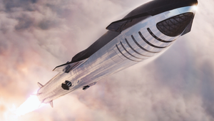
3D Printed Soft Robot
A robot with a 3D printed body that transitions from a rigid core to a soft exterior. A combustion-powered robot whose body transitions from a rigid core to a soft exterior. This stiffness gradient, spanning three orders of magnitude in modulus, from stiff plastic to squishy rubber, enables reliable interfacing between rigid driving components (controller, battery, etc.) and the primarily soft body, while enhancing performance. The core module contains a custom circuit board, high-voltage power source, battery, miniature air compressor, butane fuel cell, a bank of six solenoid valves, oxygen cartridge, pressure regulator, and an internal network of channels to facilitate interfacing between the components as necessary.


Technical Specifications
| Height | 8 |
| Radius | 15 |
| Actuators | 3 |
| Jumping height | 21 |
| 89 | |
| Number of jumps | |
| Fabrication technique | |
| Material |
Overview
A combustion-powered robot whose body transitions from a rigid core to a soft exterior. This stiffness gradient, spanning three orders of magnitude in modulus, from stiff plastic to squishy rubber, enables reliable interfacing between rigid driving components (controller, battery, etc.) and the primarily soft body, while enhancing performance.
The core module contains a custom circuit board, high-voltage power source, battery, miniature air compressor, butane fuel cell, a bank of six solenoid valves, oxygen cartridge, pressure regulator, and an internal network of channels to facilitate interfacing between the components as necessary.
Design
The project used a multimaterial 3D printer (Connex500, Stratasys) to directly print the functional body of a robot that employs soft material components for actuation, obviating the need for complex molding techniques or assembly.
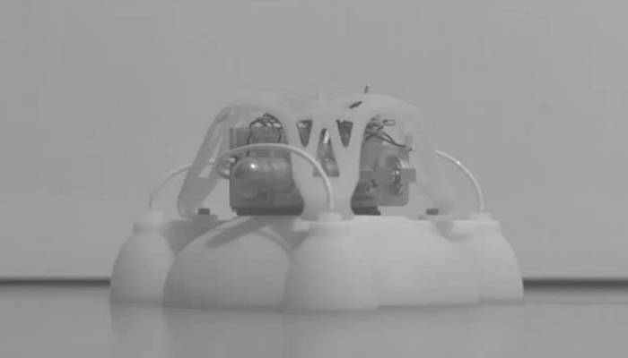
The robot body is composed primarily of two nested hemispheroids. The flexible bottom hemispheroid features a small depression that provides an initial volume into which oxygen and butane are injected. Ignition of the gases causes a volumetric expansion, launching the robot into the air (Fig. 1, A and B).
The top hemispheroid has a modulus of elasticity that ranges over three orders of magnitude (from approximately 1 MPa to 1 GPa) through a stepwise gradient of nine different layers, creating a structure that transitions from highly flexible (rubber-like) to fully rigid (thermoplastic-like).

To initiate a jump, the robot inflates a subset of its legs to tilt the body in the intended jump direction. Upon combustion, the bottom hemispheroid balloons out, pushing against the ground and propelling the robot into the air. (B) The ignition sequence consists of fuel delivery, mixing, and sparking. Butane and oxygen are alternately delivered to the combustion chamber (to promote mixing). After a short delay to promote additional mixing of the fuels, the gaseous mixture is ignited, resulting in combustion. Leg inflation occurs concurrently with fuel delivery, and leg deflation begins shortly after landing. (C) Computer-aided design model of the entire robot, consisting of the main explosive actuator surrounded by three pneumatic legs. A rigid core module that contains power and control components sits atop the main body, protected by a semisoft shield.
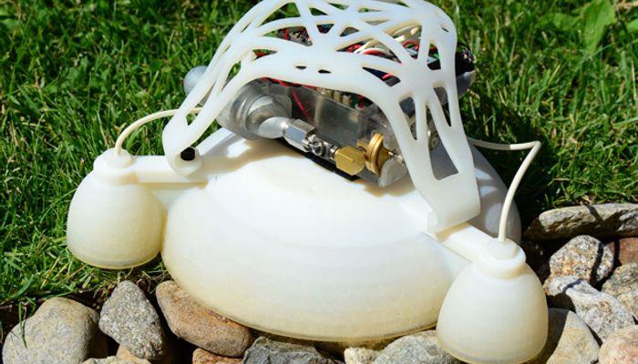
In addition to providing a mechanical interface for the rigid control components, the rigid portion of the top hemispheroid also prevents undesired expansion locally and focuses the energy of combustion into the ground, enhancing the jumping efficiency. Pneumatic legs, which use a nested hemi-ellipsoid design similar to that of the main body, surround the central explosive actuator and are used to tilt the body before a jump, controlling the direction of locomotion.
This separation of power and control actuators simplifies actuation and gives greater control over direction. In order to simplify prototyping, we chose a modular design with a rigid core module containing the control components (which are expensive and change infrequently during design iteration of the body), connected through a predefined interface to the body of the robot (Fig. 1C).
This modularity enables efficient iteration of the robot body design, as well as rapid replacement in the case of destructive testing. The core module contains a custom circuit board, high-voltage power source, battery, miniature air compressor, butane fuel cell, bank of six solenoid valves, oxygen cartridge, pressure regulator, and an internal network of channels to facilitate interfacing between the components as necessary.

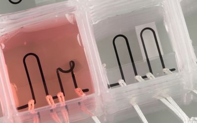
Qualitative twisting analysis comparing 3D-printed beams that are fully flexible, half rigid and half flexible, or transition gradually from rigid to flexible. These tests were performed to gain an understanding of how these materials respond, as well as to validate the numerical values of the material properties used in simulation. (Left) Material distribution of the beams. (Middle) Beams under torsion. (Right) Simulation of beams under torsion. (B) Jumping simulation. (Left) Ground reaction force as internal gases expand. (Middle) Pressure evolution inside the robot body as internal gases expand. (Right) Deformation state of rigid top, gradient top, and flexible top robot bodies at the initial state and the point of maximum simulated gas expansion. Line thicknesses indicate material stiffness. (C) Impact simulation. In the simulation, the robot strikes the ground at 45°. This angle was chosen as a particularly extreme loading condition and because it correlated with observations from jumping experiments. (Left) Reaction forces experienced by the three robots upon striking a solid plane under simulated conditions representative of actual testing conditions. (Right) FEA results of rigid top, gradient top, and flexible top robots, compared at 50 N.
The core module is mechanically attached to the rigid portion of the body with a layer of high-strength mushroom-head fasteners. Otherwise, it interfaces with the body only through four tubes (three pneumatic tubes for the legs and one tube for fuel delivery to the combustion chamber) and two wires (which produce the spark in the combustion chamber). Characterization of nine 3D-printed materials with a set of mechanical tests informed the design of the 3D-printed rigid/soft robot.
Qualitative twisting experiments are performed to gain an intuitive understanding of the response of the various materials (Fig. 2A). Mechanical testing on a universal testing machine (Instron 5544, Instron) yielded quantitative values of material properties (supplementary text). This information was used to simulate the operation of the robot using finite element analysis (FEA) software, which allowed to compare the relative efficiency of jumping robots with different material distributions. Further simulations allowed us to examine the differences in stress concentrations as a function of material distribution.
The results from these studies revealed that, when compared to an abrupt material transition, the incorporation of a graded interface could achieve a 30% reduction in maximum stress upon tensile loading, reaching a value comparable to the maximum stress observed in a soft, single-material model.
Although a perfectly smooth gradient from rigid to flexible would have been ideal, the capability of the fabrication technique was limited to a stepwise gradient of at most nine materials. The actuation strategy necessitated a flexible bottom hemispheroid, whereas the off-the-shelf control components required a rigid housing; however, the stiffness distribution of the top hemispheroid was unconstrained.
To determine how the material properties of the top hemispheroid would affect jumping, three casesare simulated: (i) a flexible top with a small rigid portion to mount control hardware, (ii) a top featuring a stiffness gradient from fully flexible to fully rigid, and (iii) a fully rigid top (Fig. 2B). Simulations showed that the flexible top was inefficient at directing the energy of combustion into the ground and propelling the robot, suggesting weak jump performance. As expected, the simulated rigid top robot produced the highest ground reaction force, whereas the gradient top robot exhibited a performance between the two extremes.

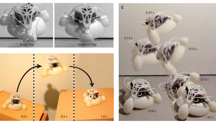
Experimental testing results. (A) Frames shortly after the moment of ground contact (Impact Comparison). Identical testing conditions were used to analyze the difference in landing between a robot with a rigid top and one with a gradient top. Because the rigid top robot jumped higher under combustion-powered testing, the gradient top robot was dropped from the maximum height achieved by the rigid top robot for a direct comparison. (Left) The rigid top robot fractures upon impact. (Right) The gradient top robot is able to absorb the impact and survive the fall. (B) Frames (Jump onto Table) at various times. The robot performs a targeted jump off of an angled surface onto a table. (Left) As the robot prepares for the jump, oxygen and butane are delivered into the combustion chamber. (Middle) Upon ignition of the fuel, the robot is propelled into the air. (Right) After jumping across a gap, the robot lands on a table. (C) Frames at various times during a directional jump. The robot pitches backward during the jump, providing a soft landing on the inflated legs. Upon impact with the ground, the robot pitches forward and returns to its pre-jump stance.
References
Provides detailed description of the project; its goal, requirements, and design approach. Furthermore, detailed description of design & features, and specifications. Mentions materials and type of 3D-printer that has been used.
A detailed description of the design and an analysis of the energetics of the jumping approach. Presents experimental results and discusses of the findings and suggestions for future work.
Recommended Specs
Continue Reading
Technique paves the way for more complex, customizable devices

3 minutes read


Addressing the risks and challenges of electrostatic discharge in manufacturing thanks to innovative 3D printing materials.

7 minutes read

“Toughness” is a combination of an object’s strength (how easily it breaks) and ductility (how easily it deforms). In this way, toughness and impact resistance are one and the same – especially in material science, as toughness is a measure for how easily your part breaks upon impact.

4 minutes read