Precision Kilovolt Sensing
A Monolithic IC for Accurate High-Voltage Measurement

15 May, 2026. 14 minutes read
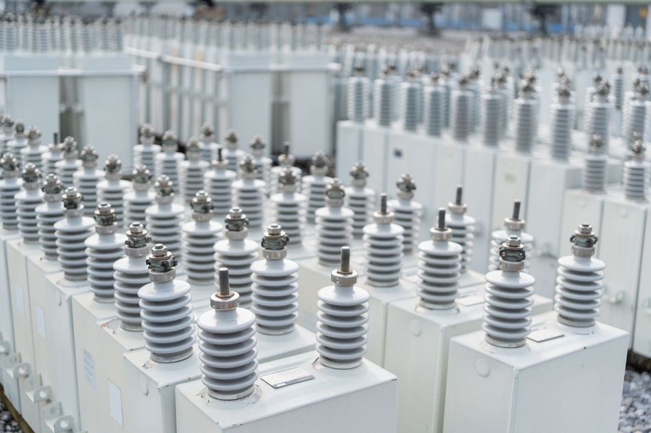
High-voltage systems are central to modern engineering across electric mobility, industrial power electronics, and medical equipment. These systems rely on accurate voltage measurement to operate within safe limits, maintain efficiency, and respond to changing conditions. High-voltage values feed directly into control loops, protection logic, and diagnostic routines. Any deviation between actual and measured voltage introduces uncertainty that propagates through the system.
Scaling high-voltage down to a measurable range appears straightforward at first glance. In practice, this task involves maintaining an accurate ratio with voltage, preserving stability across temperature, and ensuring that measurement remains reliable over time. These requirements place high-voltage sensing in a different category than for low-voltage measurement. The constraints are tighter, the consequences of error are more serious, and the design trade-offs are more complex.
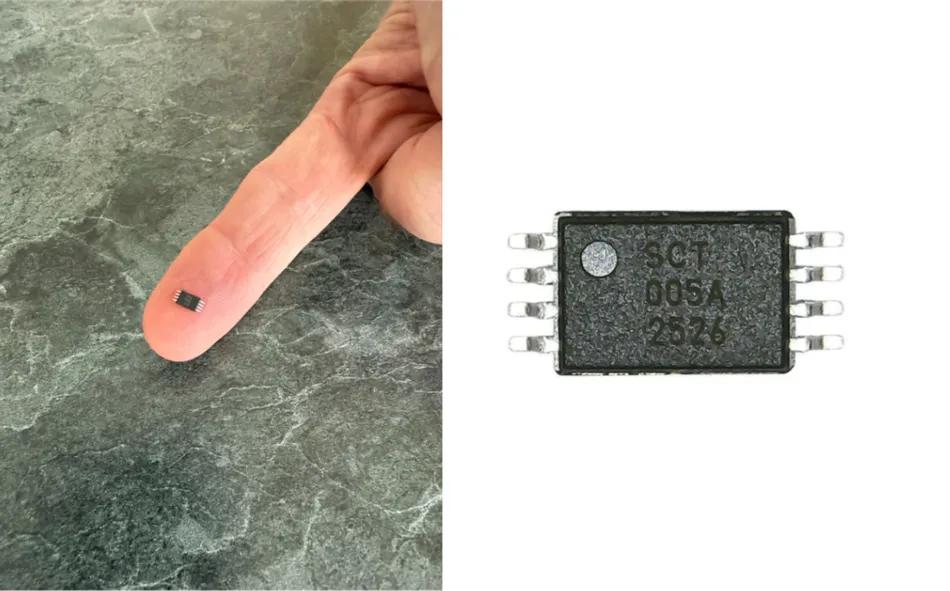
The low-cost 18SCT005 high-voltage monitor from SimpleChips addresses this challenge through a compact integrated solution, using no external components. It combines a high-precision resistor network, buffering, and filtering into a very small TSSOP8 4.4mm package. This approach enables direct conversion of high-voltage signals into a proportional low-voltage output suitable for standard electronics, while maintaining high accuracy (<0.7%) across a wide operating temperature range (-55° to 125°C).
This whitepaper examines the role of high-voltage sensing in modern electronic systems and the constraints that define its implementation. It presents an integrated ratiometric approach to voltage measurement, focusing on how stability, accuracy, and system simplicity can be achieved under real operating conditions.
The discussion is supported by a detailed look at the 18SCT005 high-voltage monitor, including its internal architecture, measurement behavior, and implementation in both DC and AC systems. Emphasis is placed on how design decisions at the sensing level influence system-level performance, from signal integrity to layout and reliability.
Why High-Voltage Measurement Becomes Difficult at System Level
High-voltage measurement is shaped by physical and electrical constraints that do not appear in low-voltage systems. Voltage levels extend into hundreds or thousands of volts. The electric field distribution across components and PCB structures becomes a design consideration. Component spacing, creepage distances, and insulation must be carefully managed. These constraints influence safety and measurement fidelity directly.
Temperature introduces another dimension. High-voltage systems often operate under load conditions that generate localized heating, and passive components respond differently depending on their material properties and placement. Even small temperature gradients can shift resistance values and alter the accuracy of voltage scaling. These effects interact with electrical conditions present in the system and can create substantial non-linearities.
High-voltage environments also include switching converters, inverters, and charge pumps that generate electrical noise across a wide frequency range. This noise couples into sensing paths and distorts measurement signals. Filtering is required to preserve signal integrity, yet filtering also influences response time and transient behavior. The sensing system must balance noise suppression with the ability to track rapid changes in voltage.
Accurate high-voltage sensing, therefore, depends on a combination of factors:
A stable scaling ratio between input and output
Immunity to electrical noise and switching artifacts
Predictable response across temperature and operating conditions
Meeting these requirements with discrete components introduces complexity and variability but remains the standard implementation in many systems.
How High Voltages are Commonly Measured Today
High-voltage measurement is usually implemented by scaling the monitored voltage down to a level that can be read by an ADC, comparator, or control circuit. The most common implementation is a resistive divider, although the practical form of that divider varies significantly depending on voltage level, accuracy target, board area, isolation requirements, and manufacturability.
In its simplest form, a resistive divider uses a high-side resistance and a low-side resistance to establish a fixed gain. For a system requiring a gain of approximately 1/320, the high-side resistance must be large enough to limit current and power dissipation while preserving the desired ratio. At kilovolt levels, this usually requires more than two discrete resistors. Designers often build long resistor chains to distribute voltage stress across multiple components and maintain safe operating margins in terms of voltage rating, power dissipation, creepage, and board-level spacing.
In other designs, series and parallel resistor combinations are used to reach a target ratio while keeping current and dissipation within acceptable limits. Some systems use a hybrid approach, pairing a high-voltage resistor with a lower-value precision resistor. Others rely on dedicated resistor networks designed for improved matching and compactness.
Each approach follows the same measurement principle, but the complete sensing chain depends on more than the nominal divider ratio. The ratio is affected by resistor tolerance, temperature coefficient, voltage coefficient, self-heating, leakage paths, and long-term drift. These effects become more important as the voltage increases and the physical implementation occupies more board area.
Thermal behavior is especially important. Resistors positioned at different locations on the board experience different temperatures. They can also dissipate substantial power under high-voltage operation, creating local self-heating. Their values drift independently, and the dividing ratio between them could change as a result, which may directly affect measurement accuracy. Voltage coefficient adds another source of variation, since high-value resistors can change resistance under high voltages.
The divider output also requires careful interface design. The low-side resistor defines the output impedance of the resistor divider. A high output impedance can affect ADC input, parasitic capacitance, and nearby switching noise. A buffer amplifier is often added to isolate the divider from downstream electronics, while filtering networks are used to attenuate noise from converters, inverters, or charge pumps. These supporting circuits improve usability while adding offset, delay, component variation, and validation effort.
Calibration can correct initial gain and offset error at a defined condition. Measurement stability still depends on how the full sensing path behaves across voltage, temperature, noise, and time. For systems where voltage feedback influences protection thresholds, energy delivery, or control-loop behavior, this residual uncertainty becomes a system-level design concern. This is the practical context for an integrated ratiometric sensing architecture.
Introducing the 18SCT005:
An Integrated Ratiometric Sensing Approach
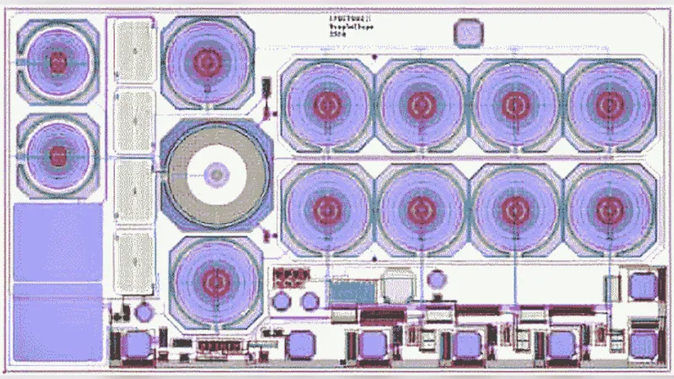
An integrated approach to high-voltage sensing addresses the limitations of discrete implementations by focusing on ratio stability at the device level. The 18SCT005, developed by SimpleChips Technology Inc., applies this principle through an integrated resistor network in which both the high-voltage and low-voltage elements are fabricated using the same material and building blocks. This creates a ratiometric system. The absolute value of resistance may vary with temperature, but the ratio between resistances remains stable across voltage and time.
The ratio defines the transfer function of the measurement. When it remains constant, the relationship between input and output voltage remains predictable across operating conditions. Such behavior is fundamental to maintaining measurement accuracy in high-voltage systems.
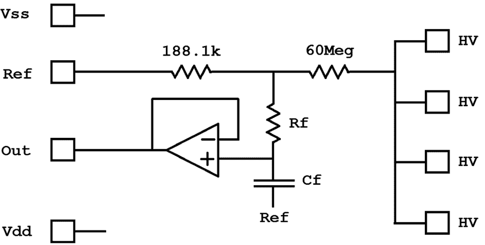
The 18SCT005 extends this architecture beyond the resistor network by integrating the supporting analog functions required for practical use:
A buffer stage that provides a low-impedance output
A second-order 1 kHz filtering stage that attenuates high-frequency noise
A reference input that defines the output baseline
These elements operate within the same physical structure and share the same thermal and process conditions. This alignment reduces mismatch, limits drift, and ensures that the sensing function behaves as a single coherent system rather than a chain of independent components.
Electrical Characteristics and Transfer Behavior of the 18SCT005
The 18SCT005 is designed to measure voltages up to ±1200V and convert them into a proportional output within the range of standard low-voltage electronics.
Key Characteristics
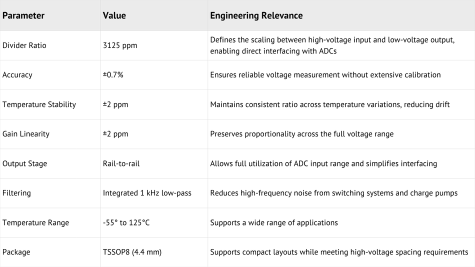
At an input of 800V, the output nominally is 2.500V, establishing a fixed scaling factor that maps high-voltage signals into a range directly compatible with standard analog-to-digital converters. This enables straightforward integration into measurement and control systems without the need for additional signal conditioning stages.
The device operates from a low-voltage supply between 2.7V and 5.5V, allowing it to interface seamlessly with embedded electronics while maintaining isolation between the sensing domain and the control domain.
The relationship between input and output is defined by a linear transfer function:

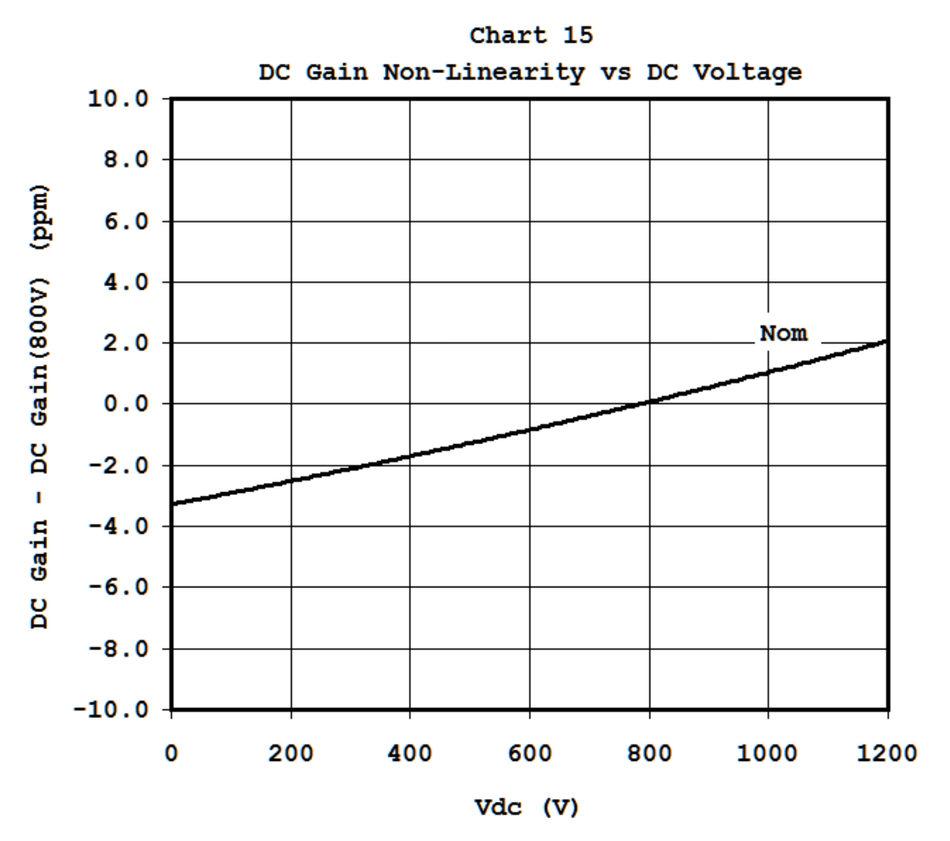
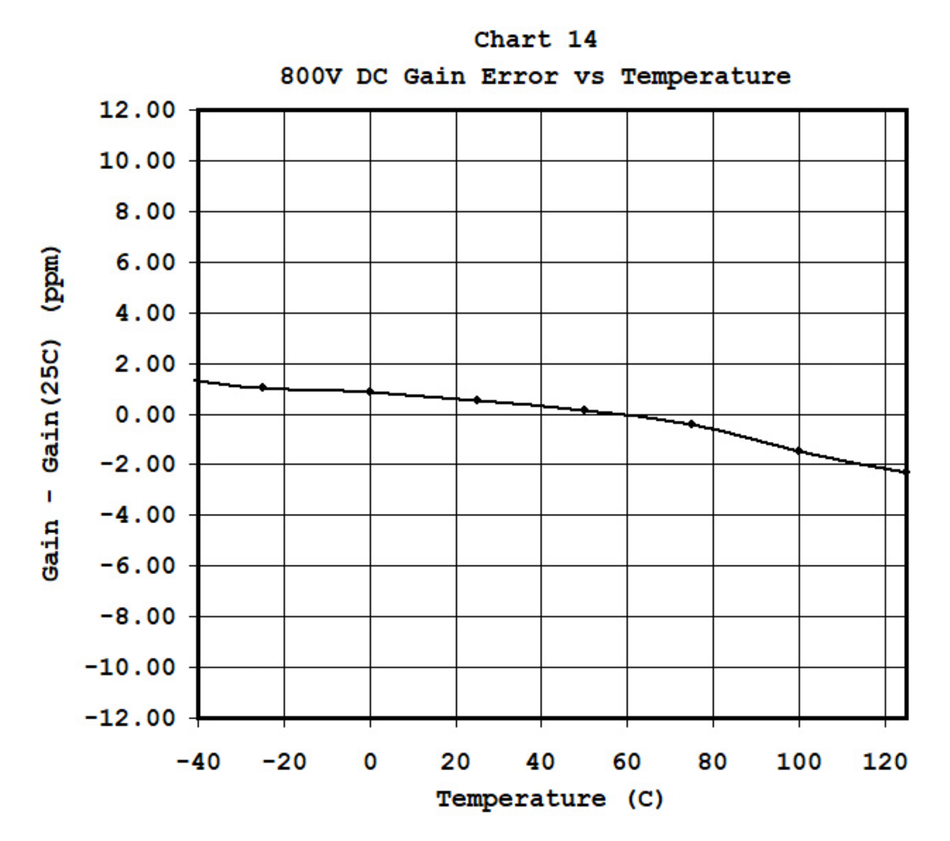
This relationship ensures that the output remains a predictable representation of the input voltage. The gain factor AV remains stable across temperature and voltage, while the offset voltage remains small relative to the measured signal. Together, these characteristics allow accurate reconstruction of the high-voltage input from the measured output across a wide range of operating conditions.
The measured gain behavior across voltage is central to this transfer accuracy. Since high-voltage monitoring depends on preserving a fixed ratio between input and output, gain non-linearity provides a direct view of how consistently the device scales the monitored voltage across its operating range.
Measurement Implementation in Real Systems
The 18SCT005 is designed to operate across a range of high-voltage measurement scenarios, supporting both DC and AC sensing within a consistent architectural framework. Its behavior remains predictable across these use cases, with the reference input defining how the output signal maps to the measured voltage.
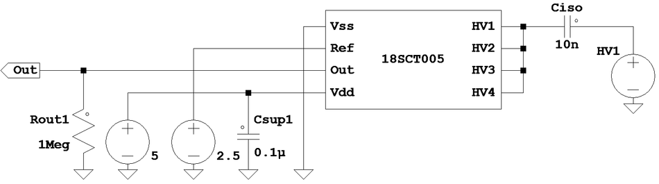
DC Measurement
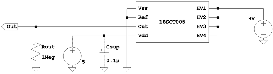
In DC applications, the reference input is typically connected to ground. The output voltage then represents a scaled version of the input voltage relative to ground, following the fixed transfer function of the device.
This configuration minimizes design complexity. The sensing path consists primarily of the IC, with only minimal external components required. A load resistor may be included to represent the input impedance of the measurement system, although no high-voltage external divider or buffering stage is needed.
The output can be connected directly to an ADC input. The stability of the gain factor ensures that conversion from output voltage to actual high voltage remains consistent across temperature and operating conditions, enabling reliable measurement without extensive calibration.
AC Measurement
For AC applications, the reference input is set to a mid-rail voltage. This allows the output signal to represent both positive and negative excursions of the input waveform within the available output range.
The choice of reference voltage determines how the waveform is centered at the output. A mid-rail reference is commonly used to maximize dynamic range and maintain symmetry around the reference point.
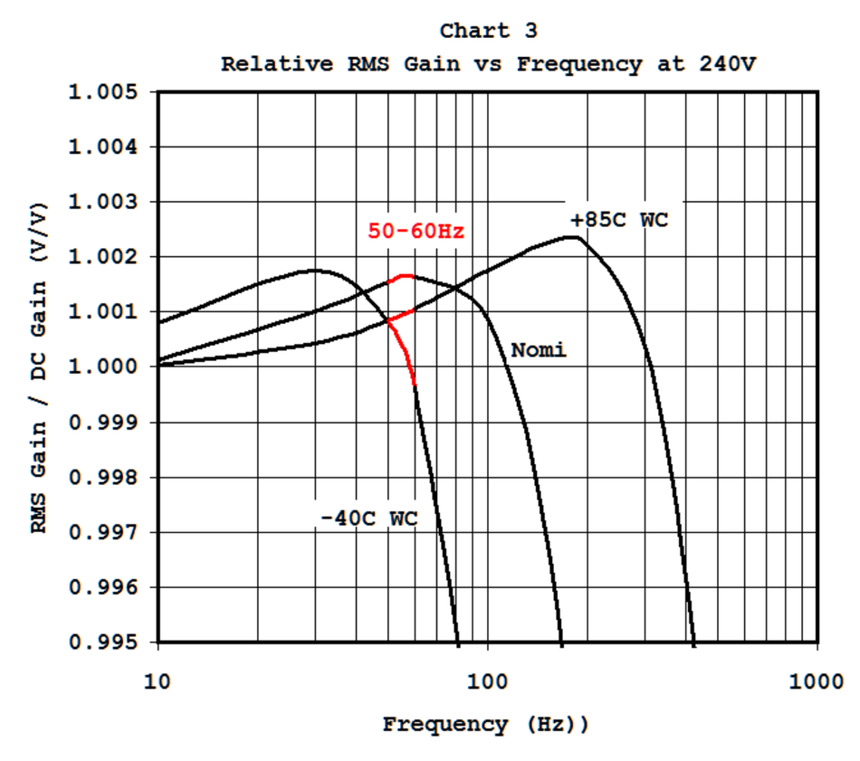
The device maintains stable gain characteristics at typical power frequencies. At 50 to 60 Hz, variation from DC gain remains minimal, allowing accurate measurement of AC voltages in power systems.
The frequency response clarifies how the 18SCT005 behaves in AC measurement. The relevant region for many power applications is around 50 to 60 Hz, where the device maintains a stable RMS gain while the integrated low-pass response attenuates higher frequency content.
This capability extends the use of the 18SCT005 beyond static measurement into applications that require continuous monitoring of alternating signals, including grid-connected systems and industrial power electronics.
Dynamic Behavior and Signal Integrity
High-voltage sensing circuits must respond to real system behavior, including switching activity, load changes, charge-pump ripple, and fault-related transitions. An effective monitor must preserve the voltage information needed by the control system while suppressing signal components that interfere with measurement accuracy.
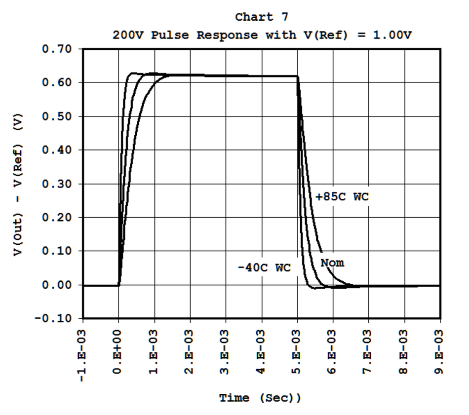
The 18SCT005 responds to step changes in input voltage with a response time of the order of 1 millisecond. This enables detection of rapid transitions and supports timely system response.
The internal filtering stage defines the frequency response of the device. A cutoff frequency of about 1 kHz attenuates high-frequency noise while preserving the signal content relevant to most applications. This balance supports accurate measurement in systems with switching activity.
Transient behavior is controlled by the internal RC network. Overshoot and undershoot remain limited, typically around 1 percent of the signal amplitude. This predictable behavior simplifies interpretation of measurement data.
Noise characteristics follow expected patterns for high-voltage sensing, where low-frequency noise increases with signal amplitude and reflects the behavior of the sensing network under high-voltage conditions. In practical systems, this noise is often compounded by switching activity from converters and charge pumps, which introduces additional disturbances into the measurement path. The integrated filtering stage attenuates these high-frequency components, preserving signal integrity and ensuring that the measured output remains stable and usable for control and monitoring.
Integration and Design Considerations
The integration of high-voltage sensing capabilities into a single IC has direct implications for system design. It affects how engineers approach PCB layout, component selection, calibration strategy, and overall system reliability. These considerations extend beyond the sensing function itself and influence the design process from early architecture decisions through to production. Cost is also always a key consideration, and integrated solutions, like the 18SCT005, offer a favorable total cost of ownership compared to equivalent discrete implementations. It is also very competitively priced, making it a compelling choice for cost-sensitive applications.
PCB Layout and High-Voltage Handling
High-voltage sensing introduces strict requirements on spacing and insulation. In discrete implementations, resistor chains and supporting circuitry must be arranged to maintain sufficient creepage and clearance distances, often leading to elongated layouts or additional board features.
The 18SCT005 simplifies this aspect of the design. Its TSSOP8 4.4mm package supports high-voltage spacing requirements up to approximately 1400V, allowing the sensing function to be implemented within a compact footprint. This reduces the need for layout workarounds such as slots or conformal coatings in many applications.
By concentrating the high-voltage interface within a defined and validated structure, the device helps maintain consistent electrical behavior while reducing layout complexity.
Component Reduction and Signal Path Simplification
In a discrete design, high-voltage sensing typically involves a chain of resistors, followed by a buffer amplifier and a filtering network. Each stage must be designed, validated, and integrated into the system.
The 18SCT005 consolidates these functions into a single signal path. The resistor network, buffer, and filter are internally matched and optimized to operate together. This removes the need for an external divider design and reduces the number of components required to implement the sensing function.
The result is a shorter and more controlled signal path. Fewer interfaces between components reduce the potential for mismatch, noise pickup, and unintended interactions. This contributes to more predictable system behavior and simplifies both design and validation.
Calibration and Measurement Stability
Calibration is often used in discrete sensing systems to compensate for resistor tolerances and initial offsets. While calibration improves initial accuracy, it does not fully address variations that occur with temperature, voltage, or long-term drift. Temperature behavior is especially important because discrete resistor networks can experience ratio movement when individual elements heat differently or carry different temperature coefficients.
The ratiometric architecture of the 18SCT005 reduces reliance on calibration by maintaining a stable relationship between input and output. Because the resistor network is fabricated on the same silicon, its ratio remains constant even as absolute resistance values shift with temperature.
This stability allows the system to maintain accuracy across operating conditions without continuous recalibration. It also reduces production complexity. A sensing function with stable ratio behavior requires less per-unit adjustment and gives system designers a more predictable relationship between measured output and actual high-voltage input.
Output Loading and Interface Stability
The output stage of the sensing system must interface with downstream electronics, which may include ADCs, filters, or monitoring circuits. These loads introduce capacitance and resistance that can influence signal behavior.
The 18SCT005 includes a buffered output capable of driving moderate capacitive loads directly. This simplifies interfacing with measurement systems and reduces the need for additional buffering.
In cases where larger capacitive loads are present, simple external networks can be used to maintain stability. These networks may slightly affect gain and transient response, but their impact remains predictable and can be accounted for during design.
Power Consumption and System Efficiency
Power consumption is a consideration in both portable and stationary systems. High-voltage sensing circuits must operate continuously, often as part of monitoring or protection functions.
The 18SCT005 draws a relatively low supply current under normal operating conditions, allowing it to be integrated into systems where energy efficiency is important. This is particularly relevant in battery-powered applications, where continuous monitoring must be achieved without significant power overhead.
The low current draw, combined with the reduction in external components, contributes to an efficient sensing solution that aligns with modern system requirements.
High-Voltage Sensing in Real-World Systems
High-voltage sensing plays a central role in systems where electrical performance and safety depend on accurate voltage awareness. The requirements vary across applications, yet they share a common need for stable and predictable measurement under operating conditions that include thermal variation, electrical noise, and dynamic load behavior.
Automotive Systems
Electric vehicles and hybrid powertrains rely on high-voltage battery systems and power electronics that operate across a wide range of conditions. Voltage measurement supports battery management, inverter control, and protection mechanisms that respond to overvoltage or undervoltage events.
In these systems, measurement accuracy must be maintained despite temperature changes, switching activity, and transient load conditions. A stable sensing function ensures that control decisions are based on reliable data, particularly during rapid changes in operating state such as acceleration, regenerative braking, or charging.
Industrial Power Systems
Industrial systems such as motor drives, power converters, and energy distribution equipment depend on continuous voltage monitoring for control and fault detection. These environments often include electrical noise from switching devices and variable load conditions that place demands on the sensing system.
Reliable voltage feedback supports stable control loops and enables detection of abnormal operating conditions. Measurement consistency across temperature and voltage range is important for maintaining performance and avoiding false triggering of protection mechanisms.
Medical Equipment
High-voltage medical devices require precise and repeatable measurement to ensure correct operation. In applications such as cardiac defibrillators, the delivered energy is proportional to the square of the voltage, therefore the accuracy of the measured voltage is of the utmost importance.
Stability over time and across operating conditions is essential. Measurement systems must provide consistent readings to support both device performance and patient safety, without introducing variability that could affect treatment outcomes.
These parameters and variables are particularly important in implanted electronics, where reliability is central to life-sustaining applications. SimpleChips takes full consideration of these requirements as the die version of this IC is available for implanted cardiac defibrillators.

System-Level Impact
The integration of high-voltage sensing into a single IC reshapes how measurement is approached at the system level. It reduces the need for discrete design steps, limits sources of mismatch, and establishes a stable transfer function that remains consistent across operating conditions.
This consistency directly influences system behavior. Control loops rely on accurate voltage feedback to maintain stability. Protection mechanisms depend on precise thresholds to respond to abnormal conditions. Measurement uncertainty in these areas leads to conservative design margins, additional validation effort, and increased system complexity.
By maintaining a stable ratio between input and output, the sensing function becomes predictable. This reduces the need for calibration and simplifies the translation from measured signal to actual system voltage. The result is a measurement chain that behaves consistently across temperature, voltage range, and time.
Integration also affects implementation. The reduction in external components shortens the signal path and simplifies PCB layout. High-voltage spacing requirements are addressed within the device package, allowing compact designs without additional layout constraints. These factors contribute to faster development cycles and more efficient use of board space.
From a system perspective, the sensing function transitions from a collection of components to a defined and validated building block. This shift improves repeatability across designs and supports scalability in production.
The low-cost 18SCT005 embodies this approach through ratiometric solutions that integrate voltage division, buffering, and filtering within a single IC, using no external components. It delivers stable and accurate measurement across high-voltage conditions while reducing design complexity and improving predictability.
This approach turns high-voltage sensing into a defined analog function within system design, supporting reliable operation across demanding electrical conditions.
For engineers evaluating high-voltage sensing solutions, SimpleChips provides technical details, application guidance, and evaluation support for teams assessing 18SCT005 integration within their systems.
Visit https://simplechips.com/.
About SimpleChips

SimpleChips is a fabless semiconductor and intellectual property provider specializing in custom integrated circuits and mixed-signal solutions. The company supports low barrier-to-entry ASIC development with flexible production volumes, addressing applications that require high-voltage capability, sensor integration, and ultra-low-power performance.
Its team brings expertise in semiconductor process engineering, analog design, wafer manufacturing, and system-level applications, supported by a portfolio of more than 40 patents. SimpleChips focuses on delivering reliable, well-engineered solutions with consistent product quality and technical support.