Display technologies for Augmented and Virtual Reality
Head-mounted devices for virtual and augmented reality come in different shapes and sizes from the minimal Google Glass to the fully immersive HTC vive. At it’s core, head-mounted displays (HMDs) consist of two primary structural elements: optics and image displays.

Last updated on 14 Aug, 2019. 8 minutes read
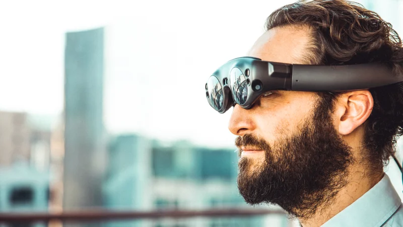
Photo by Yanick
Optics
Before looking at (pun intended) the fundamentals of optics, it is important to understand the basic properties of the human eye.
Basic properties of the human eye
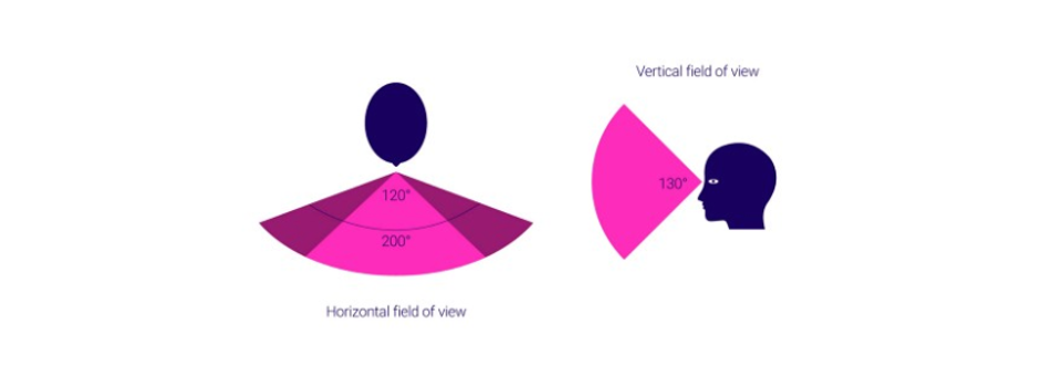
Field of View (FOV)
It is defined as the total angular size of the image visible to both the eyes. On an average, the horizontal binocular FOV is 200 deg out of which 120 deg is a binocular overlap. The binocular overlap is especially important for stereopsis and other depth cues discussed further. The vertical FOV is approximately 130 deg.
Inter-pupillary distance (IPD)
As the name suggests, it is the distance between the pupils of the eyes and is an extremely important consideration for binocular viewing systems. This distance varies from person to person, by gender and ethnicity. An inaccurate IPD consideration can result in poor eye-lens alignment, image distortion, strain on the eyes and headache. Mean IPD for adults is around 63mm with majority in the 50–75mm range. The minimum IPD for children is around 40mm.

Eye relief
This is the distance from the cornea of the eye to the surface of the first optical element. It defines the distance at which the user can obtain full viewing angles. This is an important consideration especially for people who wear corrective lenses or spectacles. Eye relief for spectacles is approximately 12mm. Enabling users to adjust the eye relief is extremely important for head mounted displays.
Exit pupil
This is the diameter of light transmitted to the eye by an optical system.
Eye box
This is the volume within which users can place their pupils to experience the visuals wholly.
The idea of displays for augmenting reality is relatively young. Most of these displays are not intended of general consumers because of the lack of everyday scenarios that can be tackled by these devices. However, defense, business, industrial and healthcare settings have shown ample opportunities for the technology to tackle. These display types can be broadly categorized as follows:
Augmenting displays
Augmenting displays can be broadly categorized into two types:
Optical see through
In Optical see through glasses, the user views reality directly through optical elements such as holographic wave guides and other systems that enable graphical overlay on the real world. Microsoft’s Hololens, Magic Leap One and the Google Glass are recent examples of optical see through smart glasses. Optical see through glasses can be either Binocular or Monocular.
Ocularity is the measure of the number of eyes needed to see something. Since most of us have a maximum of two eyes, the limit of ocularity in smart displays is likewise.
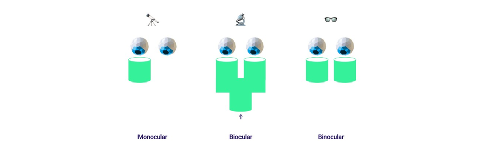
Monocular display
This display provides a single channel for viewing often through a small display element and lens. The channel is positioned in front of one eye where the user is free to view the real world completely through another eye. Monocular displays are often used as information displays due to their small form factor. However, these type of displays provide no stereo depth cues and often result in very low contrast. Google Glass and Vuzix Smart Glasses are types of monocular display.
Biocular
This type provides a single viewing channel to both eyes by means of internal reflections. Biocular displays lack stereopsis and are suitable for close proximity tasks.
Binocular
Each eye gets a separate view in these type of displays creating a stereoscopic view. These display types provide the most depth cues and a sense of immersion however, they are the heaviest, most complex and computationally intensive displays. Microsoft’s Hololens, DAQRI Smart helmet and Epson’s Moverio are all types of binocular augmenting displays.
Video see through
With these type of smart glasses, the user views reality that is first captured by one or two cameras mounted on the display. These camera views are then combined with computer generated imagery for the user to see. The HTC Vive VR headset has an inbuilt camera which is often used for creating AR experiences on the device.

Immersive displays
Most Virtual Reality headsets are fully immersive. These stereoscopic displays are combined with sensors to track position and orientation. They completely block the user’s view of the outside world like in the book ‘Ready Player One’.
Immersive headsets
Most high-performance immersive systems like the HTC Vive and Oculus Rift are PC/console driven while cheaper consumer based systems like the Google Cardboard and Samsung’s Gear VR function as standalone devices coupled with a smartphone.

Apart from VR headsets mentioned above, there is another interesting category of immersive displays that require users to wear little or no appliances on their bodies. Following are the two most popular ones.
Caves and Walls
These systems come in a variety of shapes and sizes from multiwalled displays to multi-projector hemispherical displays. These types of displays are most common in the scientific and professional communities. These are mostly multi-user scenarios where all participants experience the 3D simulations passively. These displays often have a provision for interactivity to a limited number of participants.
Hemispheres and Domes
These are popular in many industries especially defense and aviation. The provide considerable precision in graphics along with room for multiple users. The fact that these systems are untethered is a significant advantage over other immersive displays.
Each of these device types have been engineered around technologies developed for other purposes. Given the extreme resolutions of display technologies in development, it is almost certain that flat panel based HMDs might become a thing of the past for AR devices.
Optical architectures
Optics in smart glasses serve three main purposes:
- Collimation of light such that the image appears at a greater distance than it’s physical distance.
- Magnification of the display image to make it appear larger than it’s actual size.
- Relaying of light patterns to the viewers eyes.
Distortion
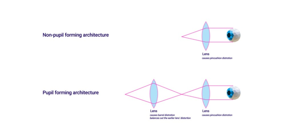
There are two primary optical design systems, or architectures for AR and VR displays: pupil forming and non-pupil forming.

Non-pupil forming architecture
These consist of a single lens and are commonly seen in popular immersive displays such as HTC Vive, Oculus Rift and Sony PSVR. This type of architecture uses a single magnifier to directly collimate light from the display panel.
Pupil forming architectures
The non-pupil forming architectures result in lighter and more compact designs with a large eye box, however they create a significant distortion when bending the light field. This effect is known as pincushion distortion. In pupil forming architectures, another lens that produces a barrel distortion is used to nullify the effect. These are often used in non-immersive type displays such as Microsoft’s Hololens and Google glass.
Waveguides
A waveguide as the name suggests is a physical structure in optics that guides a light wave to the user’s eye. This is done by means of internal reflection and the contraption controls the movement of light between entry and exit. There are four types of waveguides used in industry:
Holographic waveguide
This is a fairly simple type of wave-guide with optical elements like lenses used for in-coupling (entry) and out-coupling (exit) through a series of internal reflections. This type of waveguide is used in Sony’s Smart Eyeglass displays.

Diffractive waveguide
Precise surface relief gratings are used to achieve internal reflections for a seamless overlay of 3D graphics through the display. These waveguides are used in a number of Vuzix displays and Microsoft’s Hololens.

Polarized waveguide
Light enters the waveguide and through a series of internal reflection on a partially reflective polarized surface. Selected light waves cancel out (polarization) exiting into the viewer’s eye. The method is used by the Lumus DK-50 AR glasses.

Reflective waveguide
This is similar to the holographic waveguide in which a single planar light guide is used with one or more semi-reflective mirrors. This type of waveguide can be seen in Epson’s Moverio as well as Google Glass.

Imaging technologies
Imaging and display technologies have improved greatly in the past few decades. High end CRTs have been mostly replaced by four key imaging technologies:
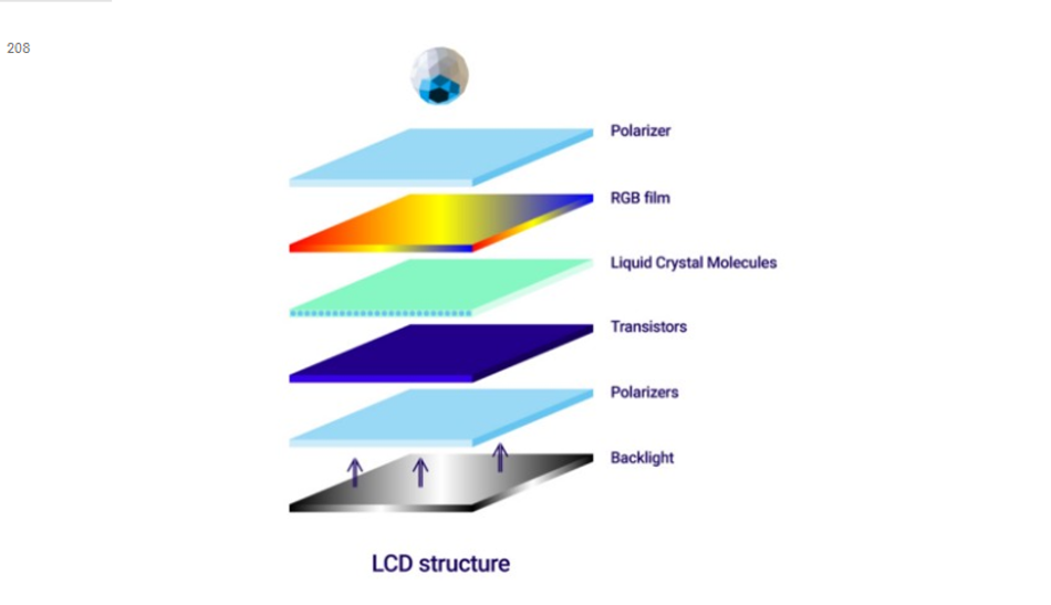
Liquid Crystal Displays (LCD)
LCDs are common in high definition televisions and have been used in ARVR displays since 1980s. This display type consists of an array of cells containing liquid crystal molecules sandwiched between two polarizing sheets. This contraption rests between thin glass substrates printed with millions of transistors. For colored LCDs, an additional substrate containing red, green and blue filters is positioned over each cell of the substrate. A single RGB liquid crystal cell is called a subpixel. Three subpixels form one pixel.
A electric current is passed through the glass substrates. Varying the current allows the LCD to modulate the passage of light to create a precise color. If all subpixels are fully open, it creates a white light.
Liquid crystal cells do not emit their own light and require backlighting. The liquid crystal cells can only vary the passage of light to create the desired color and subsequently an image.
Organic Light Emitting Diode (OLED)
This display technology is based on organic (carbon and hydrogen bonded) materials that emit light when an electric current is applied. This is a solid-state display technology where energy passed through the organic sheet is released in the form of light, also known as electroluminescence. Colors can be controlled by carefully crating organic emission, however most manufacturers add red, green and blue films in the OLED stack. There are two types of OLED panels:
- Passive Matrix OLED (PMOLED):
Like CRTs, this display type consists of a complex electronic grid to sequentially control individual pixels in each row. It does not contain storage capacitors making update rates slow and a high power consumption to maintain a pixel’s state. These are mainly used for simple character and iconic displays. - Active Matrix OLED (AMOLED):
Unlike PMOLEDs, AMOLEDs consist of a thin transistor layer that contains a storage capacitor to maintain each subpixel’s state providing greater control over individual pixels. In case on AMOLEDs, individual pixels can be completely switched off enabling deeper blacks and higher contrast. These are most suitable display types for near-eye virtual and augmented reality devices.
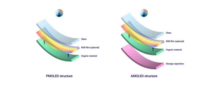
OLEDs and AMOLEDs in particular are far superior to LCDs. Their construction is relatively simpler and they can be extremely thin since there is no need of external backlighting. In addition to this they consume significantly less power, have faster refresh rates, high contrast, great color reproduction and higher resolutions. Most fully immersive HMDs utilize this technology.
Digital Light Projector (DLP) Microdisplay
Originally developed by Texas Instruments, DLP chip is also referred to as a Digital micromirror device (DMD). The display consists of about 2 million individually controlled micromirrors each which can be used to represent a single pixel. Each of these micromirrors measure approximately 5.4 microns. What is interesting about these displays is that the retina of the eye itself serves as a display surface. RGB light is reflected on these micromirrors which tilt towards and away from the light source. As each micromirror can be reoriented in either direction thousands of times in a second, varying the reflected color can produce different shades of light on the retina.
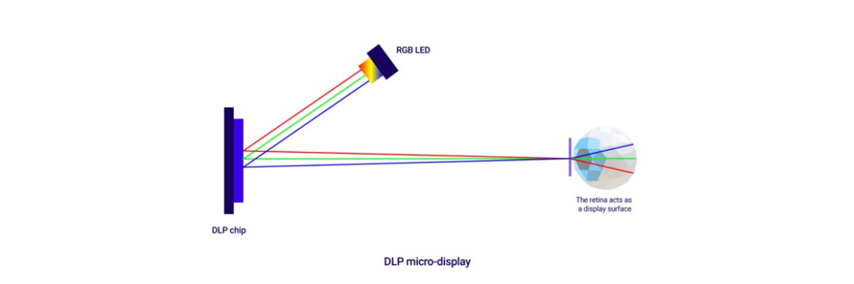
DLP Microdisplays are one of the fastest display technologies in existence. Their speed of color refresh, low latency, low power consumption and extreme high resolutions (0.3 inch array diagonal enables a 1280 x 720 image) make them ideal candidates for building head-mounted displays.

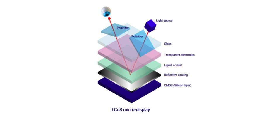
Liquid Crystal on Silicon (LCoS) Microdisplay
LCoS Displays lie somewhere in between LCD and DLP displays. LCD is a transmissive technology where the image is generated and transmitted to the user while DLP is a reflective technology where individual subpixels are reflected through micromirrors. Light source is passed onto a reflective surface. As the light reflects, it passes through a series of sub filters that modulate the light intensity and color. Similar to DLP displays, their small size enables considerable flexibility when integrating with small form factor devices. Microsoft’s Hololens, Google Glass and even the Magic Leap One uses an implementation of LCoS Microdisplays.
Given the extreme resolutions of display technologies in development, it is almost certain that flat panel based HMDs might become a thing of the past for AR devices.
[Engineer? Get the latest state of the art research in your inbox. Sign up for our newsletter.]
References:
1. Augmented Human — Helen Papagiannis
2. Practical Augmented Reality — Steve Aukstakalnis