Super Ball Bot
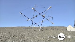
Super Ball Bot is an all-in-one landing and mobility platform based on tensegrity structur
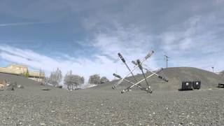
Super Ball Bot Drop and Roll


Technical Specifications
| Total mass | 100 |
| Payload Capacity | 70 |
| Number of Struts (Arms) | 6 |
| Structural Mass | 30 |
| Maximum landing velocity | 15 |
| Actuation | |
| Microcontroller used |
Overview
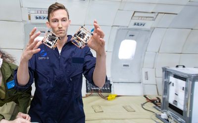
The super ball bot is small and light-weight. Teams of small, collapsible, light weight Super Ball robots, are conveniently packed during launch and will reliably separate and unpack at their destination. The robot is based on a “tensegrity” structure and built purely with tensile and compression elements.
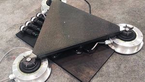
Super ball bot is composed of 12 fully independent, autonomous units, termed end caps, which slide into each end of hollow aluminium tubes to create the 6-strut robot. Each of these end caps has a single 100 W Maxon brushless DC motor for actuation, four custom PCBs which serve various purposes, batteries, wireless communication, and two internal springs as part of the spring-cable assemblies.
In Super ball bot, the tensile elements are called spring-cable assemblies and consist of a combination of steel wire cable, Vectran cable, a compression spring, sensors and optionally an actuator. Each of Super ball bot’s motors is attached to a 1.4 mm Vectran cable. The opposite end of that cable is looped onto the free end of a steel cable, close to the opposite rod, which then transfers force through the cable into a spring inside that other rod. This internal enclosure for the springs is motivated by observations from past work where environmental snagging occurred on a similar robot’s external springs.
In landing analysis, NASA developed and cross-validated two different simulation methods that allowed them to explore the capabilities of a tensegrity structure to absorb the forces of landing and to simultaneously protect a delicate payload. This analysis confirmed that it is possible to do so using a 6-bar tensegrity probe while maintaining maximum decelerations experienced by the instrument-containing payload to forces less than 25G, despite the structure landing at 15 m/s (which is greater than terminal velocity on Titan). Within the scenarios in which the probe experienced a successful landing on Titan, the maximum acceleration applied to the payload was simulated at 180m/s2(18.3G) and the minimum acceleration simulated was 140m/s2(14.3G). Comparing this to the Huygens probe’s landing acceleration of 32G [45], the tensegrtiy probe will have a 43% reduction in G forces experienced by the scientific payload.
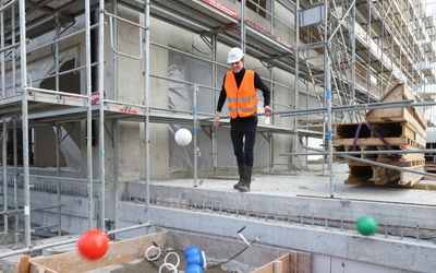
Terrestrial Drop Test Landing Speeds:
Vi= (2gd)1/2
g = 9.8 m/s^2
d = 10 m
v = 14 m/s
Expected Landing Speed on Titan = 11 m/s
Super ball bot employs four circuit boards per end cap. A custom sensor collection board, motor control board, and power distribution board are connected over a Controller Area Network (CAN) bus. A single Beaglebone Black is also housed on each endcap to directly implement high level 86 code and facilitate WiFi communications. Each of these four PCBs has at least one microcontroller, with the three custom boards using Microchip’s DSPIC33E series.
Super ball bot also has two types of wireless communication: WiFi on the Beaglebone, for data collection and high-level control, and a chip from Nordic Semiconductor on the power board that control the emergency kill switch. The functioning prototype at the conclusion of Stage-1 of the project used an Arduino Uno Microcontroller and three Arduino Motor Shields connected via a breadboard.
Tensegrities can be an effective landing and mobility platform for a Titan mission. Compared to existing flown missions, a tensegrity probe can have a high mass fraction between science payload and overall weight (as measured at atmospheric entry) due to its dual use as a landing system (like an airbag) and as a system for surface mobility. As a result, tensegrity based missions can be cheaper and open up new forms of surface exploration that take advantage of their natural tolerance to impacts. Since the robot is designed to land safely from orbit, mission controllers may be willing to take greater risks in order to access high priority science targets, such as exposed rocks on the edges of cliffs or traverse complex jagged terrain on icy moons, on the assumption that the robot could survive unplanned falls. Tensegrity robots can be applicable to a wide range of scales and solar system destinations. NIAC is currently building a next generation prototype to increase the performance and reliability of the robot.
References
Final rapport including background on tensegrity robotics, key findings, tensegrity probes for a notional mission to Titan, the hardware of the robot, and the landing structure analysis.
Evaluates tensegrity probes on the basis of the EDL phase performance of the probe in the context of a mission to Titan.
Gives background on tensegrity robots and previous work. Gives details about the tensegrity robot used in this paper. Shows how a learning algorithm can be used to create a control policy for ourtensegrity robot. Presents experimental results.
Recommended Specs
Continue Reading
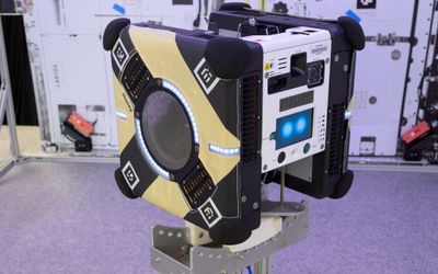
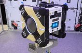
The Astrobee free-flying robots, developed in and managed by the NASA Ames Intelligent Systems Division, were setup for the second session to test an autonomous rendezvous algorithm and assist the ground team in monitoring Astrobee performance of autonomous robotic rendezvous with a tumbling target.

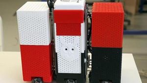
Self-reconfiguring ElectroVoxels use embedded electromagnets to test applications for space exploration.
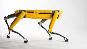
EPFL engineering student Lucas Froissart designed an exoskeleton capable of propelling robot explorers into subsurface tunnels on the moon.