Combining SLA 3D printing and soft lithography for fast, versatile, and accessible high-resolution fabrication of customised multiscale cell culture devices with complex designs
Taking advantage of low-cost, high-resolution desktop resin 3D printers combined with PDMS soft-lithography we have developed an optimised microfabrication pipeline capable of generating a wide variety of customisable devices for cell culture and tissue engineering in an easy, fast reproducible way

16 Jul, 2022. 50 minutes read
This article is a part of our University Technology Exposure Program. The program aims to recognize and reward innovation from engineering students and researchers across the globe.
Commercially available cell culture devices are designed to increase the complexity of simple cell culture models to provide better experimental platforms for biological systems. From microtopography, microwells, plating devices and microfluidic systems to larger constructs for specific applications like live imaging chamber slides, a wide variety of culture devices with different geometries have become indispensable in biology labs. However, the techniques used for their fabrication can be out of reach for most wet labs due to cost and availability of specialised equipment or the need for engineering expertise. Moreover, these techniques also have technical limitations to the volumes, shapes and dimensions they can generate. For these reasons, creating customisable devices tailored to lab-specific biological questions remains difficult to apply.
Taking advantage of low-cost, high-resolution desktop resin 3D printers combined with PDMS soft-lithography we have developed an optimised microfabrication pipeline capable of generating a wide variety of customisable devices for cell culture and tissue engineering in an easy, fast reproducible way for a fraction of the cost of conventional microfabrication or commercial alternatives. This technique enables the manufacture of complex devices across scales bridging the gap between microfabrication and fused deposition moulding (FDM) printing. The method we describe allows for the efficient treatment of resin-based 3D printed constructs for PDMS curing, using a combination of curing steps, washes and surface treatments. Together with the extensive characterisation of the fabrication pipeline, we provide several proof-of-principle applications ranging from simple 2D culture devices to large tissue engineering constructs and organoid formation systems.
We believe this methodology will be applicable in any wet lab, irrespective of prior expertise or resource availability and will therefore enable a wide adoption of tailored microfabricated devices across many fields of biology.
Introduction
Stem cell-based models are an invaluable resource, which allow the study of nearly any cell type in vitro1–4. The advent of cellular reprogramming and subsequent access to patient derived stem cell models has also galvanised their position as an ideal tool to investigate cellular processes in health and disease5–9. However, whilst stem cell models recapitulate the identity of the desired cell types, they remain a reductionist approach which sacrifices relative complexity to allow greater control over the biological processes being studied.
To overcome this limitation and exploit the full potential of stem cell models in vitro, several bioengineering strategies have been developed to combine control of cell identity with custom engineered culture environments which direct cell-cell, cell-matrix and cell-substrate interactions. One of the most common bioengineering strategies involves the introduction of microtopography to culture substrates. These substrates can be used to direct cell behaviour by patterning target proteins on the microfeatures like with micro contact printing10–13, or create custom culture vessels such as microfluidic devices14–19. Generally, fabrication of micropatterned substrates is achieved using a combination of photolithography and soft-lithography where a biocompatible substrate such as polydimethylsiloxane (PDMS) is used for cell culture applications20, 21. PDMS offers several advantages, as it is optically clear, which is making it suitable for microscopy, and has tuneable stiffness (800kPa-10MPa), allowing a broad range of modifications.
Whilst microfabrication enables the creation of advanced in vitro culture systems with microfeatures, the constructs are limited in their complexity due to the nature of photolithography techniques. In particular, photolithographic instruments can only create single layers at a time with a given height (dictated by the photoresist layer and its properties), meaning features are limited to layered 2D designs of defined thickness (i.e no 3D volumes, curves or interconnected shapes across scale). Additionally, the generation of multi-layer masters for complex features requires multiple photolithographic steps, incurring manufacturing time, risk of error and significant cost. Hence, this technique is not suitable for rapid construction of user-handleable macroscale devices with microscale features for cell culture applications. Moreover, the specialised facilities and expertise required for these techniques limit access for many labs, creating a bottleneck for wider adoption of microfabrication and sometimes resulting in dependence on costly commercially available devices that may not be optimized for specific experiments (e.g., imaging chambers for microscopy with fixed geometry or volume).
In contrast, 3D printing technology has emerged as an accessible and adaptable tool for fast prototyping and fabrication of small objects. Together with their increasing availability, rapid technological advancement for 3D printers has allowed the development of several open-source projects that aim to enable any wet lab to create and quickly adopt critical and innovative modelling strategies22–27. This is particularly important when considering the challenges experienced by laboratories in less developed countries in sourcing equipment or specific consumables, or the sometimes-steep practical barrier that some labs encounter when venturing into cell culture and biology from a different field.
Stereolithography (SLA) printing is a specific type of 3D printing based on light-curable resin, that with recent advancements in minimum resolution and pricing, shows the potential to bridge the gap between μm-resolution photolithography and cm-resolution fused deposition moulding (FDM) 3D printers, whilst remaining economically accessible to any lab. Because of these characteristics, coupled with the rapid and easy fabrication of complex shapes in 3D, SLA printing represents in theory an ideal technique to create bespoke culture vessels, inserts and other devices to increase complexity within biological experiments without sacrificing control over culture conditions 28.
Unfortunately, most commercially available resins for SLA printing are cytotoxic and cannot be used for cell culture applications29. Additionally, the composition of these resins is often proprietary, and conversion or production of biocompatible resins requires skills limited to dedicated chemistry laboratories30. Some biocompatible resins are commercially available, however, they tend to be sold at a much higher cost than even high resolution resin, and more than the actual printers in some cases (e.g Phrozen sonic mini 4K printer = GBP 365 31, 1L Zortrax Raydent Crown and Bridge resin = GBP 392 32), undermining the applicability of 3D SLA printing for cell culture purposes. Additionally, unlike PDMS and other silicon-based materials used for soft- lithography resins do not have tuneable stiffness and tend not to be optically clear.
One possible solution to these problems would be to combine PDMS soft lithography with SLA 3D printed moulds, akin to the procedure used for micropatterned silicon masters. However, curing of PDMS on SLA resin prints can be quite challenging as acrylates and triorganophosphate photoinitiators, constituents of most commercially available resins, inhibit PDMS polymerisation33–36. Furthermore, SLA-resin-induced PDMS curing inhibition makes demoulding difficult and can result in leaching of cytotoxic uncured PDMS monomers into the cell culture medium of even successfully demoulded designs37, making the devices unusable for cell culture applications.
To overcome these challenges and facilitate the production of complex 3D constructs suitable for cell culture, several successful post-processing and coating approaches have been established38–40. However, these protocols generally involve either long heat and detergent treatments, which often cause print deformation, or expensive techniques41, not accessible to every lab; for example, coating of SLA prints with parylene, which has been found to be sufficient to overcome curing inhibition of PDMS42. We aimed to overcome this lack of accessibility by optimizing a universally effective post processing protocol for soft-lithography on SLA 3D printed moulds (SOLID), using a low cost commercially available printer and materials. Once established, we focused on highlighting the versatility of this protocol for multiple cell culture applications by producing different devices which range from µm to mm and cm scale, with complex 3D shapes. Overall, our protocol can be adopted by any biology lab as a rapid and cost-effective technique that does not require specialised training or facilities.
Results
Optimisation of PDMS curing on 3D SLA printed moulds
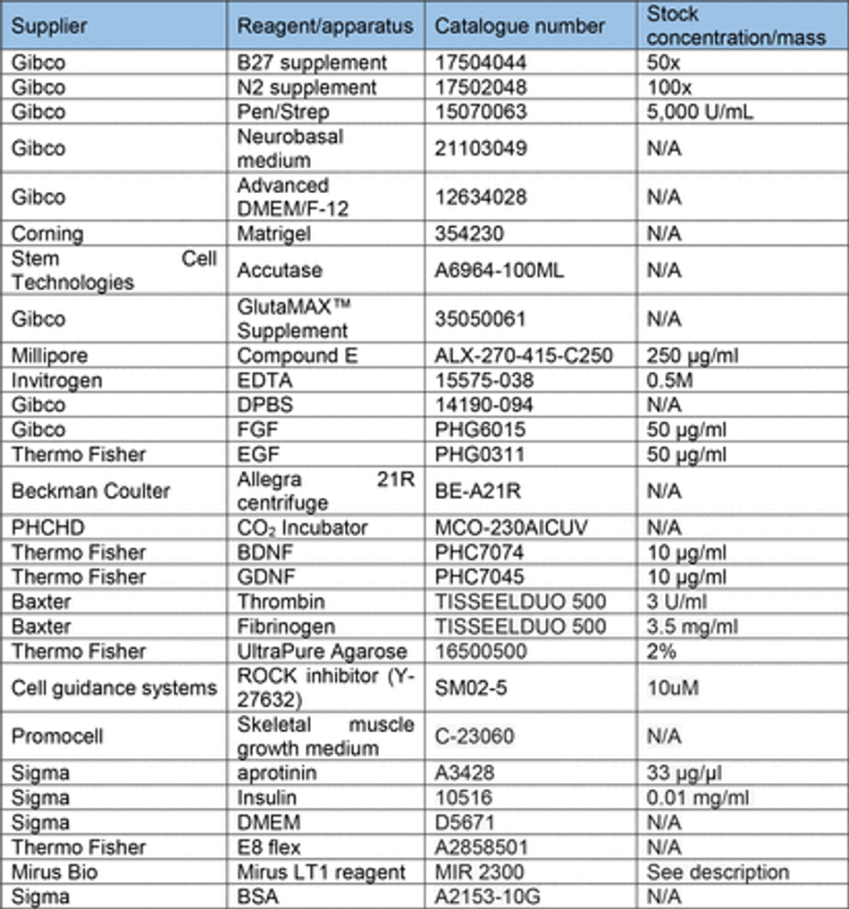
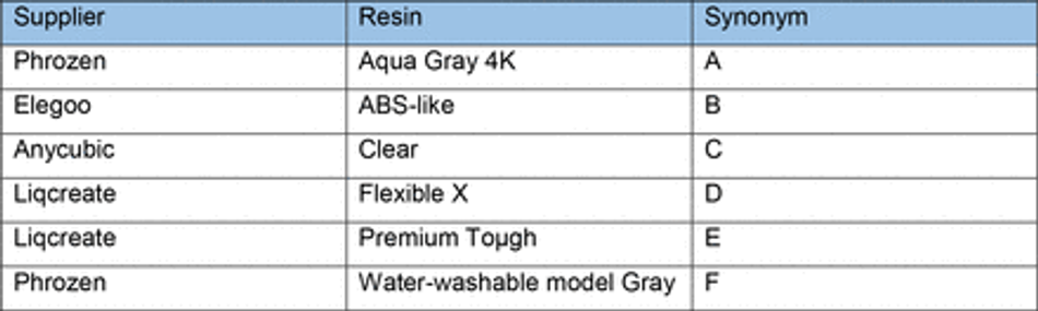
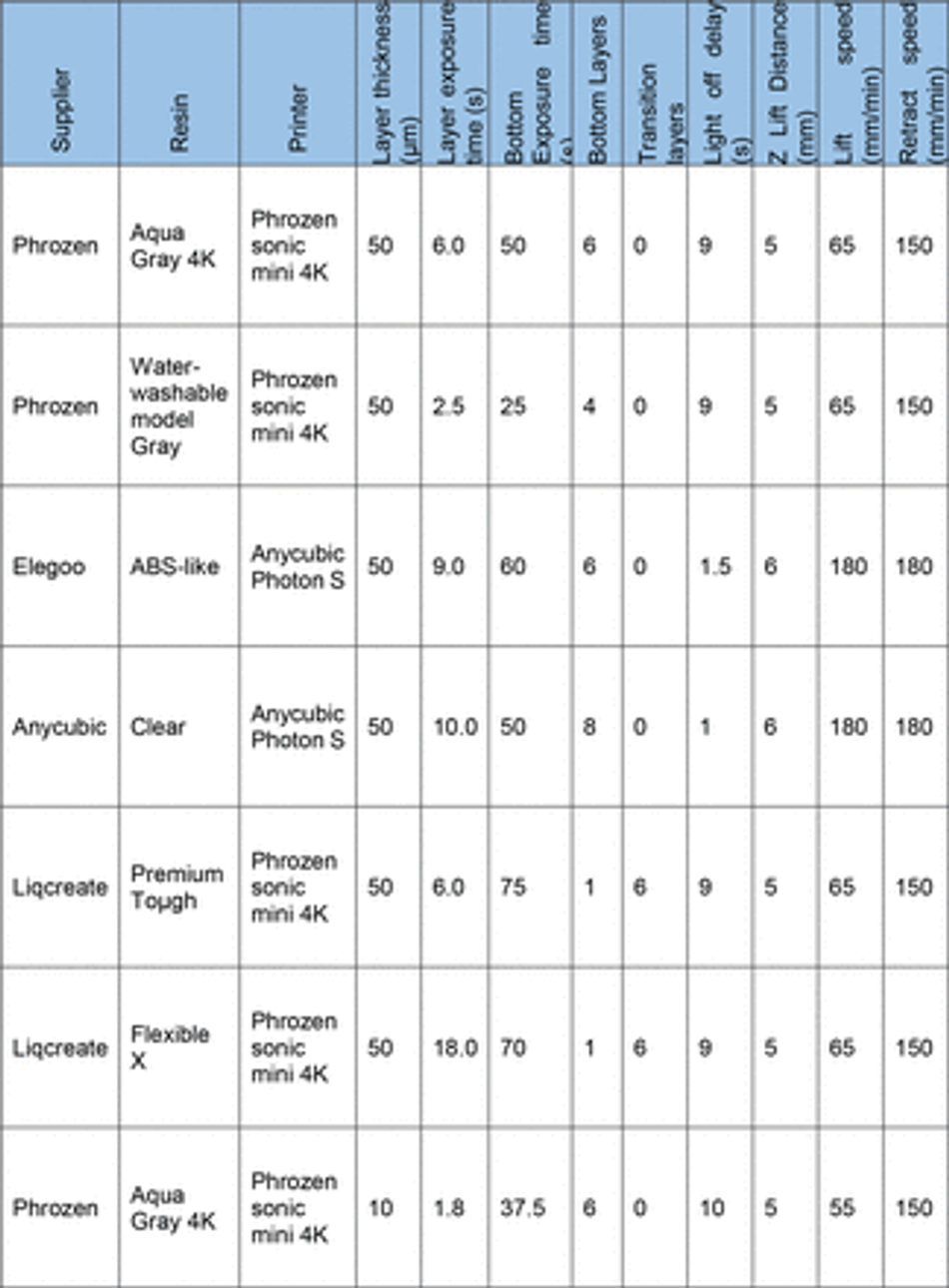
To overcome the current barriers preventing the integration of 3D SLA printing for fabrication of tissue culture constructs in biology labs, we aimed to optimise an easy- to-implement and widely applicable protocol to enable efficient PDMS curing on SLA printed moulds using commercially available equipment. We therefore tested a variety of commonly available resins (Table 3) subsampling different manufacturers together with a commercially available high-resolution 3D printer (300-400 GBP retail price, Phrozen 4K Sonic Mini or Anycubic Photon S equivalent to approx. 2 batches of a monoclonal antibody for immunostaining).
First, we verified the previously reported cytotoxicity of each resin following conventional post processing steps (isopropanol washing, UV curing), either in an untreated state or with supplementary heat treatment, washing and UV sterilisation, by co-culturing chips of resin with induced pluripotent stem cells (iPSC)-derived motor neurons (MNs) (Figure S1). We then focused on optimising the post-print processing protocol for resin moulds testing different parameters across three main steps: resin washing, print coating, and PDMS heat treatment curing (Figure 1A), to find an easy and fast method overcoming PDMS curing inhibition, as no standardised post processing protocol exists (Figure 1B). We used a simple mould design with rectangular extruded features, which later can be used to create cell-seeding stencils. Resins were printed using modified manufacturer’s settings on the recommended printer (either Anycubic or Phrozen) (Table 3) (Figure 1C). We tested PDMS curing on the moulds at 6 different time points (2h, 4h, 6h, 18h, 22h, 24h) and considered the sample conditions not optimal for curing if the process took over 30h.
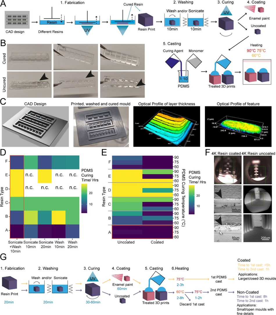
Figure 1:
Enamel paint coating facilitates rapid PDMS curing on SLA 3D printed moulds
(A) Schematic overview of the investigation strategy to establish a protocol for PDMS curing on 3D printed moulds (B) Representative images of PDMS casts removed from printed devices classified as cured or uncured. Arrows highlight liquid PDMS. (C) Representative images of a CAD of 3D SLA printed moulds, the completed print, and surface optical profiles of layer thickness and feature dimensions. (D) Heatmap of PDMS curing time by resin type for different washing conditions. (E) Heatmap of PDMS curing time by resin type for different PDMS curing temperatures (right y-axis) and different SLA print coatings. (F) Representative SEM images of uncoated (right) and enamel paint coated prints (left), arrows highlight the paint layer. (G) Schematic overview of optimised fabrication, post processing and PDMS casting protocols with (yellow) and without (purple) enamel coating
The isopropanol washing step is designed to remove excess uncured resin from the printed moulds. We tested two different methods for removal, sonication and stirring, alone or in combination, each for 10 minutes, and found that post printing washing conditions in isolation have a modest effect on PDMS curing time, but a combinatorial treatment was beneficial. Therefore, all subsequent experiments were performed using sequential treatment with sonication and washing (10 minutes each). Interestingly, we found that resin selection had more impact on curing time than washing itself, with resins A and F performing the best (Figure 1D). Washing of resin E and D was unsuccessful in most conditions, due to the amount of uncured resin adhering to the print from improper printing, and subsequent analysis of PDMS curing on these samples would bias the curing time, if curing can take place at all.
It has been suggested that curing inhibition on SLA resin can result from vaporised acrylate monomers 38, which are components of most resins, released into the PDMS during heating. We reasoned that either blocking the contact sites between acrylates and PDMS or reducing the release of acrylates from the resin during curing could be sufficient to allow efficient curing of PDMS on the moulds. To test these hypotheses, we used commercially available enamel paint to homogenously coat the washed 3D SLA prints with an airbrushing system, forming a protective barrier between the PDMS and resin. We then compared the PDMS curing time of coated prints to uncoated prints at 3 different temperatures (60, 75, 90°C), which allowed us to identify the role of temperature on acrylate release and PDMS curing. These experiments showed that enamel paint coating enabled PDMS curing not only on the surface but throughout the whole cast, and decreased PDMS curing times for all resins. It is important to note that Resin A is a special case, as it showed good PDMS curing performance with and without coating (Figure 1E), permitting the use of our post processing protocol with and without enamel paint. These two protocols differ not only in the coating but also the curing temperature used, which impacts the overall manufacturing times. The benefit of the missing paint layer of the non-coating protocol is that it allows the manufacture of detailed PDMS moulds (features <300 µm) (Figure 1G). We therefore continued in the following experiments with resin A. Overall, lower temperatures improved PDMS curing times on resins and the variation in the effect of temperature on coated samples was negligible. Additionally, we observed that high temperatures (90°C) resulted in significant warping print. These unwanted effects were less prominent at lower temperatures (60-75 °C), which were still effective enough to cure PDMS.
It has also been reported that acrylate monomers and photo-initiators, which are resin components, can leach from the resins into PDMS, impacting the biocompatibility of cast constructs 37. To verify that the cured PDMS samples did not have leachates of resins or enamel paint, we performed a Raman spectroscopy characterisation of samples from each post processing condition and compared them to cured and uncured PDMS (Figure S2). This spectral analysis revealed no detectable carryover of resin constituents or paint into the casted PDMS and high similarity of resin casts to cured PDMS. To further validate these findings, we cocultured resin print cast PDMS substrates with iPSC-derived MNs. These co-cultures demonstrated good biocompatibility over longer culturing periods (Figure S3).
As introducing a layer of enamel coating on the mould devices could negatively impact fine feature sizes, we used SEM imaging on printed moulds with resin A to quantify whether print dimensions and surface roughness were significantly affected. Analysis showed that coated prints exhibited a thin layer of paint <100 µm and greater surface roughness compared to uncoated ones (Figure S4). This limits the application of this method to features larger than 100 µm in any dimension (Figure 1F).
SOLID fabrication allows generation of complex 3D shaped stencils for precise control of cell positioning and grouping within open wells
3D printed stencil-aided dry plating can be used to control cell location and number in an open well device
Conventional open well culture systems generally do not allow control over cell position, grouping, and numbers in an easy and reproducible fashion, limiting the complexity of in vitro modelling experiments. A number of techniques are available to overcome these limitations and to create precise arrangements of cells within culture vessels -from microfluidic devices to cell bioprinting-, however this leads to highly compartmentalised structures negating the advantages of open culture systems. Additionally, most require specialised equipment (e.g. parylene43) or extensive time and resources to fabricate, which makes them difficult to implement as a routine system for most biology labs. Another approach that allows increased levels of complexity within conventional culture vessels and maintaining an open well system are stencil-like devices 44, 45, although at present these also suffer the same technical limitations as the above-mentioned strategies. Moreover, this method is especially affected by the geometrical limitations of feature extrusion across volumes resulting in thin devices with limited possibility of customisation.
We decided to use this application, using human induced pluripotent stem cell derived motor neurons (MNs) as a model system, for an initial proof-of-principle of our optimised SOLID protocol, based on an engineered platform we recently developed for MN cultures using a micropatterned substrate to facilitate axonal elongation46. We combined and optimised this platform with our SOLID moulding protocol to create a tailored plating strategy for investigating hiPSC-derived MN behaviour with control over cell location and orientation. We designed moulds for casting PDMS stencil-well devices, rectangular extruded features with funnel shaped media reservoirs as complex 3D features to ease cell seeding. This optimised design permits rapid and facile manual seeding as cells can settle into micro-sized wells in a suitable volume of medium to avoid excessive evaporation and cell death (Figure 2 A-B).
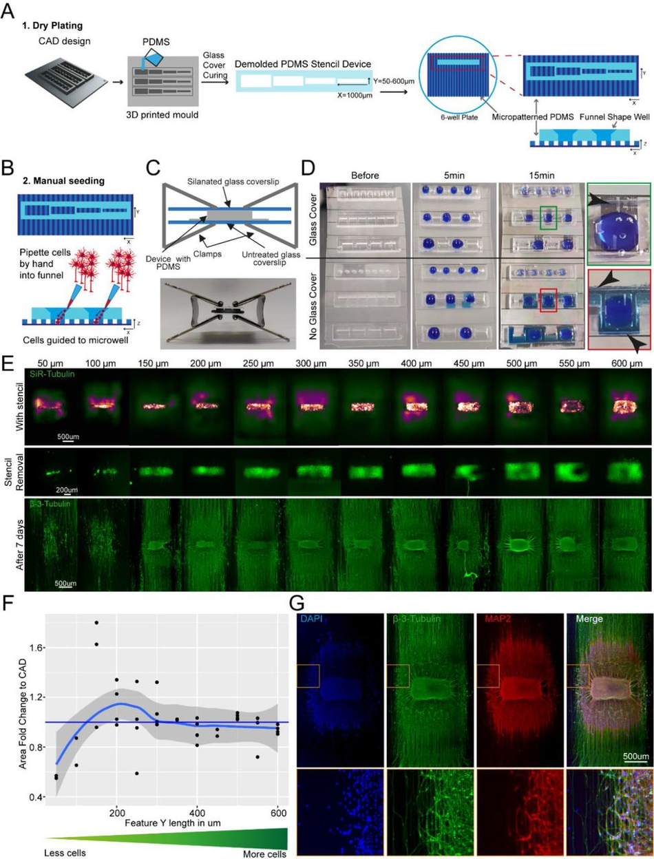
Figure 2:
SLA 3D printing enables control over cell location and number in an open well (A) Schematic overview of the investigation dry plating strategy to combine PDMS casts from 3D printed molds with PDMS microgroove substrate to control cell body location and number. Well sizes range from 600 µm x 1000 µm to 50 µm x 1000 µm in 50 µm intervals (B) Schematic overview of funnel shape well for easy manual seeding in microwells. Schematic (top) and representative image (bottom) of clamping approach to ensure fluid seal when devices are placed on PDMS microgroove substrates. (D) Comparison of liquid seal integrity of clamping strategy (top) compared to open curing (bottom) on PDMS microgroove substrate with different well sizes and shapes using dyed liquid. Successful sealing of devices cast with a glass cover (Green zoom). Dye spreads throughout device and grooves using open cured (Red zoom). Arrows highlight liquid spreading. (E) Representative images of stencil devices filled with pre stained (Silicon Rhodamine-tubulin) MN progenitors with device still in place (top), after device removal (middle), and axonal β-III Tubulin following fixation after 7 days of culture (bottom). (F) Comparison of seeded cell area after stencil removal to CAD specified values by fold change G) Representative images of 3D aggregoid with 2D axon elongation stained with DAPI (1st image), axonal β-III Tubulin (2nd image), and Dendritic MAP-2 (3rd image) simultaneously (4th image).
PDMS stencils from these 3D moulds allow seeding by “dry plating”, whereby a stencil is placed in a dry conventional tissue culture plastic vessel and cells in suspension are manually pipetted in the stencil device, isolating the cell bodies from the residual well and allowing them to adhere at these specific positions. With the cell bodies secured, the stencil device can be removed and the whole well filled with culture medium, while the adhered cells remain in their specified position. For this “dry plating” process, a strong fluidic seal surrounding the PDMS stencil wells is necessary, requiring a flat surface between stencil and substrate below. Without specific steps to adjust the surface roughness of prints, PDMS casts from 3D printed moulds are inherently rougher than those from micropatterned silicon wafers used for casting microfabricated PDMS devices (Figure S5). We therefore implemented an additional clamping step before PDMS curing, using a silanised glass slide (see M&M) to cover the PDMS surface, which is in contact with air, taking advantage of the flat surface provided by the glass (Figure 2C). We evaluated the efficiency of clamp-cured stencil fluid seals when placed on a PDMS micropatterned surface with 10 x 10 µm-grooves using a blue dye. An effective seal was achieved in all stencils cured using the additional clamping, denoted by dye reaching the microgroove substrate in the well area only and spreading within these specific grooves. Stencils cast without clamping showed uncontrolled dye spreading throughout the devices, verifying a lack of fluid seal (Figure 2D).
We then applied the stencil devices to a biological application investigating the minimum number of iPSC-MNs required to form a self-organised 3D neural aggregate on microgrooves for axonal elongation, a process determined by chemotaxis and topography. To achieve this, we used the above-described stencils with a funnel shaped reservoir and rectangular wells, varying in Y-dimension to reduce the stencil well size and control cell amount. The well dimensions were homogenous and faithful to CAD specifications throughout the print sizes down to 50 µm in Y (Figure S6). These PDMS stencil-well devices were placed on the extra cellular matrix (ECM) coated and dried micropatterned surface with axonal guidance grooves46, and the iPSC-derived MN cell suspension was manually pipetted into the dry wells of the device. To avoid potential air pockets in the smaller wells, as it is common for non- functionalised PDMS, we performed oxygen plasma treatment on stencils prior to cell “dry plating” (Figure S7). Compact rectangular “aggregoids” (i.e. 3D cell clusters generated by reaggregating single cells from a culture) with decreasing size were achieved during seeding and were maintained following device removal. Staining with β-III-tubulin after 7 days in differentiation medium revealed that wells with a size of down to 150 µm provide suitable cell numbers for aggregate formation. However, the two smallest well sizes did not provide the environment for aggregate formation and cells migrated across the topography (Figure 2E-F). Subsequent staining with compartment specific markers showed a clear separation between dendrites and axons in the open well devices of compact aggregoids (Figure 2G). In summary, stencil-well devices cast with SOLID can be used to control cell location in an open well, facilitate control over different cell numbers in the same device, and enable cell compartment specific investigations.
Spatial and temporal control over cell-cell interaction using tailored plating devices
We next explored the potential to use SOLID for more complex cultures, incorporating different cell types and plating steps. First, to plate multiple cell populations within the same devices we sought to take advantage of PDMS natural hydrophobicity coupled with the large rectangular well design and funnel shaped well profile showed in Fig.2A. The high contact angle between media and hydrophobic PDMS allows to achieve confinement of the different cell suspension droplets, which generates enabling complete fluidic separation between adjacent wells containing different cell populations, even with manual plating. We sought to utilise this strategy to simultaneously plate different iPSC derived MNs populations within the same well in different spatially separate groups. For this we used fluorescent RFP+ and untransfected MNs, which we plated manually within adjacent wells within the same device placed on an ECM coated well of a 6-well plate. The different cell populations were left to adhere for 2h before the plating device was removed. After removing the device and further cell culture for 72 hours, all MNs were stained with a silicon rhodamine tubulin dye, to visualise all neurites and cell bodies. A line graph analysis across the whole device showed that all wells contained MNs (RFP+ and RFP-) and in every second well, RFP+ cells were present (Figure 3A-B), demonstrating multi cell type seeding in confined predetermined spatial groups within a single device
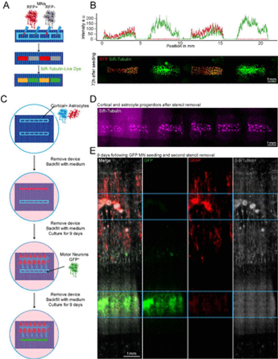
Figure 3:
Plating devices enable spatiotemporal control of cell plating for construction of complex neural circuits Schematic overview of alternate seeding of RFP and non-RFP+ motor neurons in the same device and the following live cell staining (B) Representative line profile of stained across the well showing segregation of individual populations to their designated wells – RFP+ only in wells 1 and 3, but SiR-tubulin+ in all wells (top). Representative fluorescent images of stained RFP+/- motor neurons (bottom) (C) Schematic overview of the multidevice protocol for constructing a neural circuit using 2 stencil devices and 3 different cell types (MNs, cortical and astrocytes) with seeding performed at different time points (D) Representative SiR tubulin live cell dye fluorescence images of astrocyte and cortical progenitors. Images were captured 2 days following device removal (E) Composite and channel split of complete circuit after 19 days of culture. GFP transfected motor neurons = green, Glial Fibrillary Acidic Protein (GFAP) identifies astrocytes, β-III – Tubulin identifies cortical neurons and the tubulin in GFP+ motor neurons. Blue device well shapes overlaid for illustrative purposes.
We then sought to further increase complexity of our in vitro cultures using SOLID fabricated plating devices by seeding multiple cell types at different time points within the same well, taking advantage of the efficient and reversible fluid seal between our devices and the culture plate. For this, we placed two rectangular well plating devices, approximately 2mm apart from each other on an ECM coated micropatterned surface within a well of a 6-well plate, as described above. Initially, one device was used to dry plate iPSC-derived cortical neurons47 and astrocytes48 in a 1:1 ratio and removed after 24h, while the other device was kept empty. The whole tissue culture well was then filled with differentiation medium and cultured for 9 days. During this time, cortical axons guided by the microtopography extended towards the empty device, which maintained its initial fluidic seal even surrounded by medium. On day 9, GFP+ MNs were seeded in the second device by first lowering the level of the medium within the well to be below the edge of the plating device, and then seeding the MNs in suspension directly within it. After allowing for cell attachment, the second device was also removed, the well refilled with fresh medium and cells cultured for further 9 days. The position of the different cell types was then verified using immunocytochemistry (ICC) for astrocytes (GFAP) and neurons (both MNs and cortical neurons, β-III Tubulin), as cortical neurons could be identified by overlap of GFP and β-III Tubulin. Using this tailored removable SOLID-generated plating devices we were able to easily plate 3 different cell types at 2 different timepoints within the same culture well, creating a complex neural circuit and demonstrating true spatiotemporal control over cell seeding in a cost-effective and highly adaptable fashion (Figure 3C-E). Additionally, we demonstrated also multiple time point seedings within the same well using large-format “nesting” plating devices which can be used to construct large-scale cell and tissue arrangements (Figure S8).
Generation of large-scale 3D constructs for organoids and multicellular circuitry modelling
Next, we tested whether the ease of available prototyping using our optimised SOLID protocol could enable investigation and manipulation of the fundamental behaviour of complex iPSC-derived MN cultures. It has been shown that aggregation of cells using different geometries has an influence on the signalling environment and patterning of organoids49. We therefore designed and fabricated moulds for PDMS stencils with 3 different well shapes: rectangular, circular, and triangular, to create geometrically constrained neural aggregates. With the advantage of volumetric 3D printing, we were able to preserve the funnel reservoir and straight well design from previous moulds (Figure 4A). Using these multi-shaped stencils, we seeded motor neuron progenitors (MNPs) as before on our micropatterned substrate and allowed axons to extend for 11 days (Figure 4A left). Here, MN aggregates maintained faithful area and aspect ratios to CAD specifications on day 2 after stencil removal. After 11 days, the groups also retained their specific geometry although showed slight changes in the aspect ratio and area over time (Figure 4B-D). Next, we used these PDMS stencils on nonpatterned and uncoated tissue culture plastics to avoid cell adherence, directing self-organisation of organoid-like structures (Figure 4A right). Here, we seeded cortical progenitors in Matrigel and were able to generate differently shaped organoids demonstrated by SiR-tubulin live dye images after 24 hours (Figure 4E). SOLID fabrication can therefore be used as a valid method of fabricating constructs for controlling cellular interactions in complex cultures of multiple geometries for both 2.5 (i.e. partially tridimensional adherent cultures) and 3D non-adherent cultures (e.g. organoids) depending on the seeding substrate.
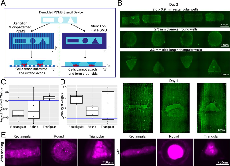
Figure 4:
Plating devices enable geometric manipulation of aggregoid cultures in 2D and 3D Schematic overview of protocol for manipulating aggregate geometry in combination with existing microgroove and flat substrates. (B) Representative images of SiR-tubulin live-cell stained motor neuron aggregoids at day 2 (top) and β-III Tubulin staining after 11 days (bottom) of culture. (C) Boxplot of aggregoid aspect ratio fold change by shape between CAD (blue line) and day 2 of culture from β-III Tubulin channel (top) (D) Boxplot of aggregoid area fold change by shape between CAD (blue line) and day 2 of culture from β-III Tubulin channel. (E) Representative images of SiR-tubulin stained cortical aggregates after seeding and 24h later in different geometry stencil devices, round (left), triangular (middle) and rectangular (right).
Customisable SOLID fabrication as a tailored alternative to standardised commercially available culture platform
The ability to create customisable devices and substrates suitable for cell culture or other biological experiments, with μm to cm sized features, in a fast, reliable and cost- efficient manner would be particularly useful in any wet lab, granting independence from high costs, delivery times and availability of the equivalent commercial products, while enabling limitless customisation. For example, most cell culture vessel layouts are generalised and not tailored to the need of an individual laboratory or a specific cell type, causing higher costs and potential compromises in experimental setups. We therefore aimed to test whether our optimised SOLID mould protocol could be used to reproduce and further customise relevant features from popular commercially available cell culture products. These constructs can be customised in dimensions and/or shapes for individual experimental aims, while remaining cost-effective, highlighting the versatility and accessibility of our system to enhance biological investigations.
Custom microwell arrays for embryoid body formation.
The first design we tested for this purpose was an array of pyramidal-shaped microwells (390 x 350 x 150 µm) which we fabricated using the optimised protocol with no coating step, as it is required for this small feature size (<500 μm) (Figure 5A-B). These microwells have become essential for induction of specific cell lineages from iPSCs and for organoid research50, 51. One of the most important functions of these wells is to ensure homogenous aggregate size for reproducible results, for example, generating embryoid bodies (EBs) of regular size and shape. We used our SLA moulded microwell arrays to form EBs from an iPSCs suspension (Figure 5C) and quantified their size after 4 days of culture on the devices. In our microwells, iPSCs formed EBs with consistent diameters, verifying the suitability of our custom PDMS moulds to create small regular arrays of features (Figure 5D). The microwells generated by our protocol are therefore suitable for generation of homogenous EBs with the benefit of almost limitless customisation of well shape and size at a low cost.
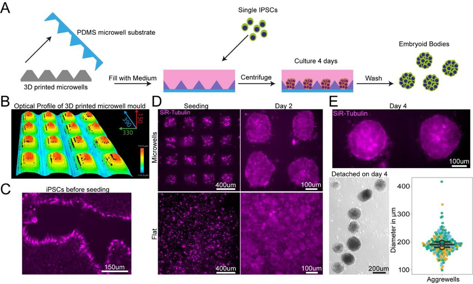
Figure 5:
PDMS substrates cast from 3D printed devices permit regular sized embryoid body Schematic of design, manufacturing and seeding of IPSCs on microwells (B) Representative optical profile of 3D printed microwell device with well sizes of 390 µm length x 350 µm width x 150 µm height. (C) Representative SiR-tubulin live cell dye images of IPSCs before seeding in microwell mould cast. (D) Representative SiR-tubulin live cell dye images of IPSCs seeded on PDMS cast from 3D printed microwell device compared to flat PDMS substrate after seeding (left) and 2 days culture (right). (E) Representative SiR-tubulin image of fused embryoid bodies on microwell PDMS mould prior to detachment after 4 days in culture (top) and embryoid bodies following washing off the PDMS microwell substrate (bottom left). Quantification of embryoid body diameter detached from microwell PDMS mould demonstrates homogenous size of embryoid bodies (bottom right).
PDMS bonding for chamber slide devices.
Chamber slide systems and other microscopy-ready hybrid culture devices are commercially available systems that allow cells to be cultured within neighbouring wells directly on cover slides for high resolution imaging, providing small well sizes and imaging-compatible set-ups for high throughput and convenience. To ascertain if our SOLID protocol could be applied to mimic these constructs, we designed a chamber slide system which can be permanently bonded to an imaging coverslip either using oxygen plasma treatment or a UV sensitive resin adhesive. Importantly, the adaptation of our construct for use with UV resin makes this method accessible to labs without a plasma cleaning system (Figure 6A). Our design was fabricated using the SOLID protocol and was size matched to a 60 mm x 24 mm microscopy coverslip with 12 circular wells with funnel shapes. As described above, we generated a fluidic seal by clamping the device with a glass slide during PDMS curing to isolate neighbouring wells. This extremely flat PDMS surface allows fusion of PDMS to the glass slide using oxygen plasma bonding, or the simple application of a UV adhesive. It is important to note that the UV adhesive is resin based and therefore cytotoxic and cannot be used on any medium facing area. Astrocyte progenitors were then seeded into selected wells at different concentrations (Figure 6B). Staining with a live dye (SiR-Tubulin) revealed an intact fluidic seal in both devices, liquids maintained in the respective wells, and healthy astrocyte progenitor populations. Ostensibly, we have demonstrated that both oxygen plasma and UV resin are suitable for PDMS bonding of a chamber slide device and highlighted the capabilities of SLA 3D printing for the fabrication of bespoke chamber slides in a fast and cost-effective way.
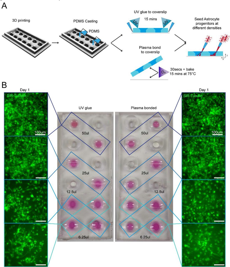
Figure 6:
3D printing can create fully customisable imaging chambers with complex well geometry suitable for cell culture via two different methods of PDMS bonding Schematic overview of design and manufacture of chamber slide device with large wells with (1) UV glue or (2) oxygen plasma bonding to a glass coverslip to seal the wells. As demonstration of the seal quality and viability for cell culture astrocyte progenitors were seeded in different densities in non-adjacent wells and cultured in chamber slide device. (B) Representative images of SiR-tubulin live dye-stained astrocyte progenitors 1 day after seeding in chamber slides bonded with different methods.
Large tissue engineered devices with complex designs.
Generating complex devices for tissue engineering often combines relatively small features within large constructs and has so far proven challenging to implement in most laboratories, as construction processes are complex and time consuming, requiring the dedicated expertise. Most devices of this kind are therefore sourced from commercially available suppliers, with limited possibility of customisation and at high cost. For example, tissue engineered 3D muscle constructs use a variety of devices for suspending large cell laden hydrogels during culture using thin suspension posts 52, 53. They are comprised of small pillars with complex shaped end-feet, which serve to suspend the hydrogel construct and provide mechanical stiffness to aid differentiation. As these posts are difficult to manufacture and arrive pre-made of a single size and shape, no customisation is available, e.g. miniaturization or altered substrate stiffness.
We used our SOLID protocol to fabricate a device for suspended 3D muscle culture with customisable post size and overall dimensions. The challenge in this case stems from the fact that these devices do not have large flat faces, they present thin complex features, and need ideally to be produced as a single component to avoid complex assembly steps that can introduce variability. A single mould system would in this case not be sufficient, as the lack of air in contact with the complex shapes would prohibit the successful demoulding of the structure. Hence, we created a two-part mould/injection system using SOLID, which can easily be assembled by clamping for curing after PDMS is poured into the mould. Optimisation of the moulds showed that an unequal distribution of the design between the two parts (70/30) is beneficial for successful demoulding (Figure S9), resulting in a reproducible single device with the desired dimensions, in this case twice as large as the commercial alternative – a 2cm muscle compatible with 12-well plates (Figure 7 A). We compared our 12-well plate 3D posts to the commercially available 24-well adapted equivalent (see M&M, Muscle culture), using immortalised myoblasts.
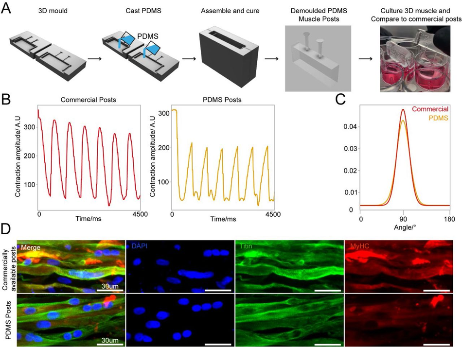
Figure 7:
3D sandwich moulds for PDMS casting to generate complex cell culture devices (A) Schematic overview of design and PDMS casting strategy for a 3D sandwich mould. Immortalised myoblast hydrogels were then formed around PDMS posts, differentiated and cultured for 2 weeks. (B) Comparative contractility analysis with microstimulation at 20mV with 0.5Hz frequency of differentiated 3D muscle between crafted PDMS posts and commercially available posts. (C) Directionality analysis of fiber alignment in differentiated 3D muscle fibers between PDMS posts and commercially available posts after 2 weeks differentiation. (D) Representative images of myoblast differentiation (Titin) and developmental stage (MyHC) on PDMS posts and commercially available posts after 2 weeks differentiation.
Following the protocol to generate 3D bioengineered muscle constructs described by Maffioletti and co-workers53, we first created a pouring mould by filling liquid agarose around a 3D printed rectangular spacer which was removed after the agarose has set (Figure S9). Subsequently, myoblasts were seeded in fibrin hydrogels within the agarose mould, and the SOLID fabricated posts (or commercially available devices 54 used in Maffioletti et al.) were inserted within the still settling fibrin constructs53. After 2 weeks of differentiation, we performed electrical microstimulation to measure muscle contractility – a hallmark of successful 3D muscle culture- on both constructs at 20mV with 0.5Hz frequency (Figure 7 B), which showed periodic contractions for both SOLID and control devices. Immunostaining of the muscle tissue showed presence of terminally differentiated myosin heavy chain (MyHC) and titin positive multi-nucleated fibres in both constructs. Directionality analysis revealed that myofibres were preferentially aligned along the posts (Figure 7 C, D). In summary, our protocol allows for complex and small features to be easily moulded in PDMS comparable to commercially available 3D muscle systems with the additional benefit of customisation in all aspects of design for improved function.
Discussion
In this study we have developed a fast and cost-effective protocol to quickly prototype highly versatile cell culture compatible devices that can be applied to a range of different applications, from live cell imaging to microfluidics and even advanced tissue engineering, which we have called Soft-lithography with 3D Resin moulds using SLA Printing (SOLID). This methodology allows any lab, even those with very minimal prior expertise in the field or without dedicated resources, to effectively set up a complete microfabrication prototyping system and produce culture devices tailored to their specific biological experiments with minimum expenditure.
The widespread commercialisation of SLA printing has led to a significant development of resolution and accessibility, which accompanied by free repositories and software packages, have significantly lowered the entry barrier for the adoption of this technique. As a result of this rapid development and sheer number of new resins and printers becoming available, it is difficult to get an overview of the suitable protocols and materials for a given application. A general protocol for printing and fabrication using any commercially available product is therefore highly desirable.
We have capitalised on these technological and community developments to overcome one of the primary barriers to complex microfabrication in a biology focused lab by developing and testing a robust pipeline of fabrication for SLA 3D printing, post- processing and PDMS casting, which enables for complete customisation of any cell culture device without further establishment or optimisation. We tested resins from various manufacturers and identified one suitable for PDMS casting and high- resolution prints. In particular, Resin A performed optimally without application of a paint layer for high resolution prints. This feature allows users to exploit the full potential of high-resolution prints, making ink coating for small details redundant40 . Interestingly, this resin was originally developed for high resolution printing, and has noticeably lower viscosity than other resins we tested, parameters to consider when evaluating different resin compositions for this method. However, enclosed prints like the large tissue culture constructs (Figure 7) would still not be able to cure sufficiently without a coating layer which isolates the PDMS from the mould. We also tested Resin A with a different commercially available mid-price SL printer and found no observable difference in print quality, PDMS curing, or biocompatibility, showing easy transfer of optimised parameters for resins to multiple printer systems and designs (data not shown).
When considering microfabricated devices for biological experiments, especially with cell culture and other in vitro set-ups, the topographical features one might want to add can range roughly from sub-cellular scale (<5 μm, e.g. nanoindentations55 and other nanostructures56), cellular scale (10-100μm e.g. microgrooves57 and other microwells58), multicellular (200-1000μm e.g. microfluidic channels59) or tissue scale (>1mm e.g. organoid culture devices60). In the vast majority of microfabrication pipelines, there is a practical gap at the interface between the cellular and multicellular scale, as conventional photolithography is mostly suited for precise features on the smaller scales and is less suited for multicellular scale. Moreover, combining efficiently multiple fabrication rounds across scales is sometimes challenging, time consuming and error prone. Instead, methodologies like SOLID are capable of simultaneously combining cellular, multicellular and tissue scale features within the same fabrication round, effectively filling a gap in the potential toolkits currently available.
Another advantage here is that SOLID is not tied to any particular brand of printer or resin, and as such can work for any combination (we have tested several resins over 3 different printers) and with the advent of higher resolution printers this gap might become significantly smaller. We have also demonstrated the versatility of our pipeline by successfully developing cell culture devices of different designs targeted to a wide range of applications, which either confers new capabilities to conventional culture systems (e.g. easily plating multiple cell types on precise spatiotemporal relationship) or customisation of bioengineered culture systems.
While a number of studies have already proposed similar protocols (e.g. heat curing61, UV light62, micro-diamond coating63), they all generally tend to either have a considerably lower resolution, or in some cases require obligatory steps with very expensive specialised equipment that is not generally available to most biological labs. Moreover, the chemicals and materials used in several of these processes require a much higher degree of training and expertise compared to the pipeline presented here, which requires no hazardous processes or chemicals, but only non-toxic and easily handleable components, and could therefore be implemented in a lab without risk.
In its most minimal implementation, SOLID requires only a high-resolution desktop SLA printer, a suitable resin, PDMS and everyday cell culture and microscopy components. All of these resources can be obtained with an initial investment below the cost of 2 vials of monoclonal antibodies, and at an estimated running cost of <300USD per year to produce regular medium size batches of devices, which would be affordable to any lab that has an ongoing budget for cell culture consumables. For context, a commercially available single-use 8-well chamber slide suitable for live microscopy with fixed dimensions and no possibility of customisation, ranges between 10 and 15 USD, while a single microfluidic device costs from 50 to 120 USD, both of which can be easily replaced by SOLID.
One caveat to the capability of the method, which is a limitation due to the properties of PDMS rather than the fabrication process, is that while it is possible to create complex devices without any specialised equipment to effectively use smaller features (Figure 2), a step of oxygen plasma treatment was necessary. However, plasma etchers are not available to all labs, potentially limiting the applicability of this protocol. Wang and colleagues tested alternatives to plasma treatment of PDMS persorption of fibronectin sufficient for Caco-2 cells64, hence plasma treatment might not be necessary for all cell types and has to be assessed individually.
Unfortunately, the low compatibility of most SLA resin with cell culture experiments also poses limitations to the potential application of this method and SLA printing in general. We have characterised several different commercially available resins and found that all of them, in a treated or untreated state, are cytotoxic (Figure S1). There are some biocompatible alternatives available on the market (although the extent to which biocompatibility, as defined for dental implants, can be directly applied to stem cell cultures and other more sensitive biological systems needs to be verified) to overcome this fundamental limitation of 3D SLA printing, but for a far higher price than any standard resin. Additionally, the fact that resin composition is generally proprietary limits the possible customisations that end-users can achieve. Some providers have recently started publishing their resin composition as well as customised resins generated from a number of research groups that can be recreated, although the burden of adoption of these unique formulations is likely to prevent their use in most cases65–67. Alternatively, modifications of PDMS to be printable can lead to decreased resolution of the print, undermining the strong advantage of high-resolution printer for microfabrication using resins30. The solution we implemented for the well-known curing inhibition issues with resin moulds and PDMS is to extract and cure completely the resin first with a multistep preparation (see Figure 1) and then further shield the PDMS with a layer of enamel coating.
The use of PDMS in cell culture experiments has a long history and we have decades of experience with its use with cells and in microscopy applications, however it also has some potential drawbacks. In particular, several groups have reported that PDMS can retain organic molecules and adsorb other substances, which can severely impact biological and biochemical experiments in particular cases 37, 68–70. However, one advantage of this setup is that it can be used for any soft-lithography material, for example polymers such as Flexdym, polymethylmetacrylate, or poly(DL-lactide-co- glycolide), as well as with any hydrogel or cure-forming material with a temperature below 70 degrees.
With this system we aim to empower any lab, regardless of its capabilities, access to resources or prior expertise, to create customised microdevices with features tailored to their specific biological experiments and designed with their biological question in mind, which will significantly lower the barrier for experimentation with microfabrication and tissue engineering applications in any field.
Materials & Methods
Cell culture
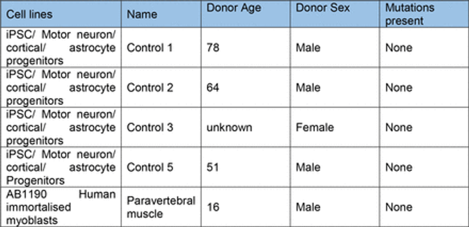
Control hiPSC motor neuron and cortical neuron progenitors were derived as described71 from multiple donors (Table 2). These cells were cultured on Matrigel (Corning) coated plates in base medium, comprised of 50% NeuroBasal (Gibco), 50% advanced DMEM (Gibco), supplemented with B27 and N2 (gibco),100 µg/ml Pen-Strep (Gibco), and 2mM L-alanyl-L- glutamine dipeptide (Gibco). For expansion of progenitors, FGF (20 ng/ml) (Gibco) was added to base medium. Differentiation of MN progenitors was achieved using base medium with compound E (Enzo) (0.1 uM) and the growth factors BDNF (10 ng/ml) and GDNF (10 ng/ml) unless stated. Astrocytes were generated from iPSC using a modified protocol described in Hall et al71. Derived astrocyte progenitors were cultured in neuronal base medium with FGF (20 ng/ml) (Gibco) and EGF (20 ng/ml) (Thermo). For differentiation astrocytes were cultured in base medium without growth factor supplements. All cells were cultured with 5% CO2 in humidified atmosphere at 37°C (Table 1).
Transfection of MNPs
For transfection of cells a plasmid based Piggybac transposon system was used with pgK- Puro-CMV-GFP and pPb-CAG-RFP-Hygro construct cloned in the lab and a PiggyBac vector containing the transposase. Motor neuron progenitors were sparsely cultured on a 24-well plate and one day after passaging transfected using Mirus LT1 (Mirus Bio) transfection reagent. Plasmids were added at total 0.5 µg per well (GFP/RFP+ transposase containing plasmid) in 200 µl of Pen-Strep free growth medium. This solution was gently mixed before addition to the wells which also contained 200 µl of Pen-Strep free medium. The medium containing the transfection reagent was exchanged with growth medium after 24h. Cells were cultured to confluency and then pooled into a 6-well plate for further expansion.
Fabrication
SLA 3D printing
3D printed moulds were designed using fusion 36072 and tinkercad73 computer aided design software, then exported as .stl (stereolithography) files to either Chitubox or Photon workshop slicing software. These softwares were used to define print parameters such as layer thickness, layer UV exposure time, and lifting/retract speeds for each resin. All resins, printers and print settings can be found in Table 3 and Table 4.
Post processing
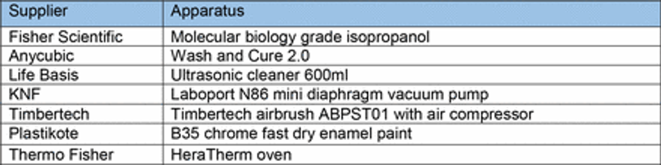
After printing, constructs were washed in fresh isopropanol (IPA) using either/or/both an ultrasonic cleaner and stirring washing bath (Anycubic). Washing method and time were varied as part of the protocol establishment. To ensure fair comparison, washing IPA was filtered for every resin for a given washing condition to remove resin components from previous washes. After washing, all prints were cured in a commercially available curing chamber (Anycubic) for 60 mins. Constructs were then selectively coated with a layer of enamel paint (Plastikote) using a hobbyist airbrushing system (Timbertech) diluted 70:30 with water as per manufacture instructions. Painted casts were left to dry at room temperature on the bench for at least an hour before PDMS casting (Table 5).
Microfabrication of patterned substrates
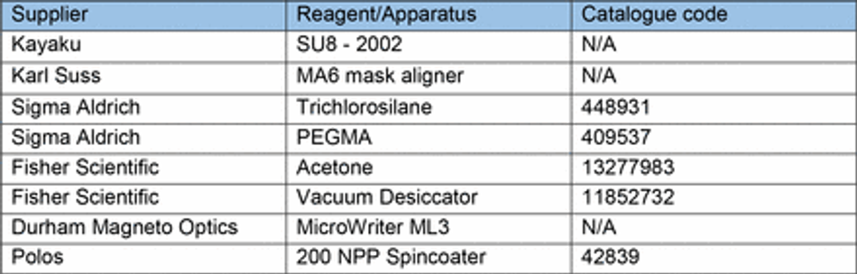
Microgroove substrates were manufactured from silicon masters patterned using photolithography as previously described 74. Briefly, SU-8 2002 (Kayaku) was spun on a silicon wafer for 40s at 1000 rpm on a spin coater (Polos) and prebaked at 95 °C for 2 minutes. A microgroove pattern designed in CleWin5 and containing 10x10 µm grooves with 250 µm plateaus every 5 mm was then etched into the SU-8 via UV exposure and an aligned photomask with the design (Kiss MA6 mask aligner). Excess SU-8 was cleaned with PEGMA, then soft and hard baked at 95°C for 5 mins, before being silanized with trichlorosilane (C8H4Cl3F13Si) in a vacuum chamber for 1 hour. Excess silane was then washed off from masters with 100% acetone. An unpatterned silicon wafer was used for flat substrates. For comparison of surface roughness between 3D printed casts and microfabricated substrates, etching was achieved by a single photolithographic step using a MicroWriter ML3 (Durham Magneto Optics) to form a pattern designed to mimic the potential capabilities of 3D printing in microfabrication. Following the photolithographic step, PDMS casts (prepared as above) were made of the flat or micropatterned silicon wafers, spin coated at 300 rpm for 40s on a spin coater (Polos) to ensure uniform thickness and cured on a hotplate at 100 °C for 5-10 minutes (Table 6).
PDMS
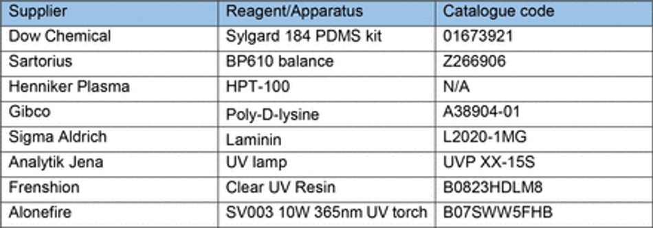
Sylgard-184™ silicone elastomer kit PDMS pre-polymer was well mixed (5 mins) with curing agent at a 1:10 w/w ratio using a digital balance (Sartorius BP610) prior to vacuum desiccation and casting at various temperatures (60-90°C).
Biofunctionalisation
Biofunctionalisation of PDMS substrates and casts from 3D printed moulds was achieved using oxygen plasma treatment (30s, 50%, 7sccm – unless stated otherwise) (Henniker Plasma). Additional biofunctionalisation of micropatterned PDMS substrates to facilitate cellular attachment was achieved using a coat of poly-D-Lysine 0.01% (PDL) (Gibco) for 15 min and laminin (Sigma) overnight (unless stated otherwise) (Table 7).
Cell Seeding
Cells were detached from culture using Accutase (Stem Cell Technologies) and seeded in oxygen plasma treated PDMS constructs cast from 3D printed moulds bound to either tissue culture plastic, flat PDMS, or micropatterned PDMS substrates. Cells were concentrated to 300 µl per detached well and seeded in differentiation media with Compound E (Milipore). Following initial plating, cells were left to settle for 2 hours in constructs. Cells were then washed 2x with PBS to remove unattached cells from constructs and wells filled with differentiation media supplemented with Compound E with constructs left in place. After 24 hours in culture, cells were washed with PBS and constructs removed before a 1:100 Matrigel spike for >2 hours and culturing cells (as above) in differentiation media supplemented with Compound E for 7 days (or as stated). For longer term experiments media was selectively supplemented with additional BDNF and GDNF growth factors depending on the experiment.
Immunostaining
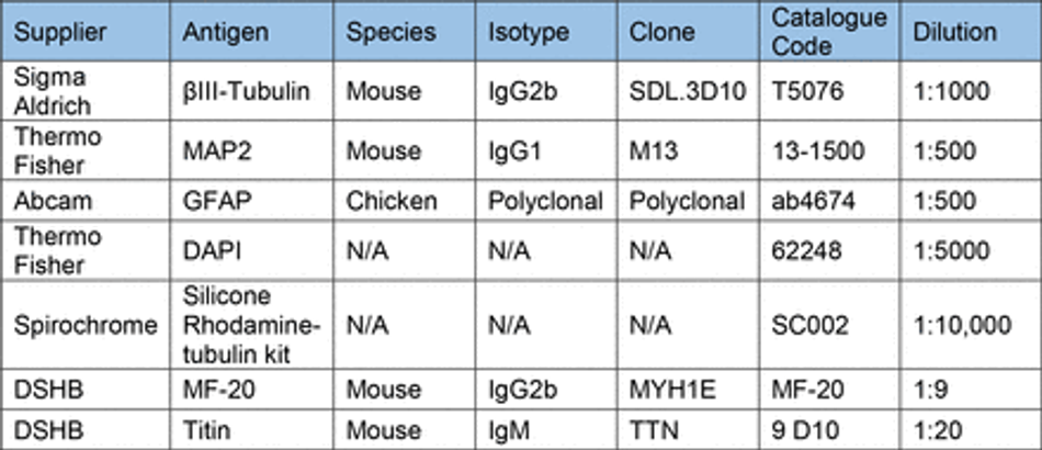
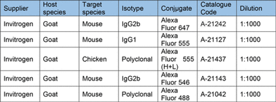
Prior to staining cells were fixed in 4% PFA (Boster) for 15 min (unless stated otherwise) and washed 3x with PBS. Cells were then permeabilized with 0.1% Triton-X for 10 min and blocked with 3% goat serum (GS) (Sigma) for 30 mins at room temperature (unless stated otherwise). Antibodies diluted in 0.05% Triton-X and 1.5% GS in PBS were then used to stain cells for markers of interest. Antibodies and their concentrations can be found in Table 10. Primary antibodies were incubated for 1 hour at room temperature in the dark, before washing 3x with PBS. Secondary antibodies were then incubated for 30 min at room temperature in the dark, before washing 3x with PBS. All secondary antibodies were incubated at a final concentration of 2 µg/ml (Table 11). For some experiments, stained cells were then mounted on glass slides using FluorSave (Millipore). Otherwise, cells were kept in PBS at 4°C until imaging. For live cell imaging cells were incubated with 1:10,000 (100nM) silicon rhodamine tubulin (SiR) live cell dye (Spirochrome) for 1 hour before removal of the dye and imaging.

Microscopy
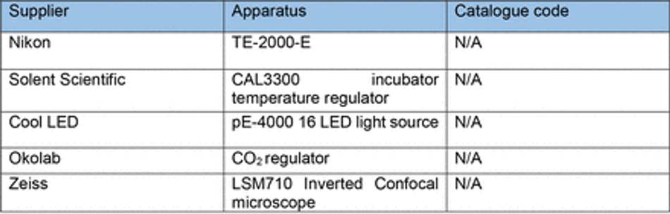
Cells were imaged using an encased Nikon eclipse TE2000-E fluorescence microscope running Micromanager software with 4x, 20x LWD and 20x SWD objectives, cool LED pE- 4000 16 LED light source, and a Prior controlled stage. An LED driver Arduino controlled light source provided illumination for brightfield imaging. To allow longitudinal and live imaging, the microscope chamber was humidified and heated to 37.0°C with 5% CO2 using a CAL3300 incubator temperature regulator (Solent Scientific) and CO2 regulator (Okolab). Humidity, CO2 balance, and temperature were regulated by further encasing the plate in a sealed custom 3D printed chamber with humidified CO2 inlet.
Surface Characterisation
Optical profilometry
Quantification of 3D printed mould dimensions and surface roughness was achieved using a Sensofar S Neox optical profilometer to measure features in X and Y, and layer thickness. Multi-image z-stacks were captured over stitching areas with 25% overlap using a 20x Nikon EPI objective and surface-variation scanning mode. For analysis of patterned silicon master feature dimensions and PDMS cast surface roughness from both 3D printed moulds and silicon masters, multi-image z-stacks were captured of stitching areas with 25% overlap using a 20x Nikon DI objective and confocal scanning mode. Analysis of features was conducted using in-built analysis tools. Plane correction was conducted on all images to reduce bias within imaged ROIs.
SEM
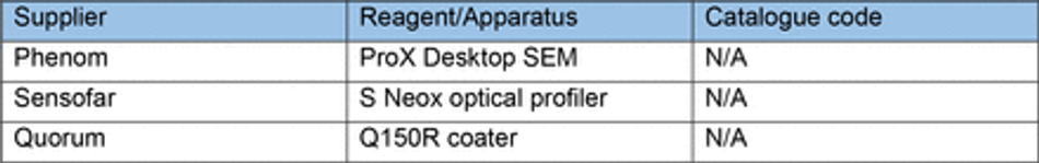
Samples of coated and uncoated 3D printed moulds were sputter coated with a 10 nm thick layer of Platinum using a Quorum Q150R coater and imaged by a Phenom ProX Desktop SEM (Thermo Scientific) at an acceleration voltage of 10kV (unless noise was too high, then 5kV was used). Images of the surface and cross section of prints was captured to investigate the thickness of applied paint and identify changes in surface roughness/topography. Images were processed in ImageJ FIJI 75(Table 8).
Image analysis
All image analysis was conducted in ImageJ FIJI software, processed using R, and presented with R or super-plots-of-data app 76 unless stated otherwise.
Line Graph Analysis
To quantify cellular segregation within the same device/multiple devices threshold fluorescence intensity was adapted to improve signal-to-noise ratio. A rectangular area was then drawn over the cells of interest and fluorescence intensity plots were obtained for each point.
Area and aspect ratio
Measurements of seeded cell area and aspect ratios were compared to either CAD specifications or 3D printed mould feature dimensions. Cell measurements were taken from the borders of aggregates using tubulin markers Silicon-Rhodamine tubulin (live) and βIII- tubulin (fixed). 3D printed mould dimensions were obtained using SensoScan software in-built analysis tools.
Resin biocompatibility
Chips from each of the 6 resins printed using 50 µm layer thickness printer settings (Table 4) and post processed as above (20 mins sonication & wash, 60 mins UV cure) without enamel coating. Chips were then either sterilised with UV for 15 mins, or baked for 4 hours at 75°C, washed in PBS for 72 hours at 50°C, and UV sterilized for 15 mins before being added to cultures of motor neuron progenitors pre-stained with SiR-tubulin cytoskeletal live dye. Cells incubated with untreated chips were left for 48 hours before imaging. Cells incubated with treated resin chips were live imaged for the first 24 hours in culture, then again at 48 hours with control wells not containing any resin
Microwell arrays
Microwell arrays of repeating 400 µm x 400 µm x 150 µm pyramids were 3D printed at 10 µm layer thickness (Table 4) and post processed as above (20 mins sonication & wash, 60 mins UV cure) without enamel coating. PDMS (prepared as above) was casted and left un- biofunctionalised to enhance EB formation through PDMS hydrophobicity. Single IPSCs pre- stained with SiR-Tubulin live dye were then seeded on microwell arrays or flat PDMS in E8 flex medium (Thermo) and centrifuged for 1 min at 100 rpm to settle cells into microwells. Cells were cultured for 4 days, imaged directly after seeding, and at day 2 and 4 of culture. After imaging on day 4 the regular EBs were detached from microwells and imaged to measure their size.
Chamber slide
Manufacture
A 3D design with 12 wells with 5 mm diameter funnel and 3 mm diameter 1 mm deep straight well was 3D printed with Resin A at 50 µm layer thickness (Table 3) on the Phrozen Sonic mini 4K and post processed as above (20 mins sonication & wash, 60 mins UV cure) with enamel coating. PDMS (prepared as above) casts were made of the arrays and bonded to glass coverslips with two methods.
PDMS bonding Oxygen Plasma
The surface of PDMS casts from 3D printed moulds and glass coverslips were oxygen plasma treated (30s, 50%, 7sccm) (Henniker Plasma), sealed together, and baked at 75°C for 15 mins.
UV glue
The surface of PDMS casts from 3D printed moulds was sealed on glass coverslips and clear photopolymerisable resin was applied round the exterior of the PDMS. Resin was cured via 1 minute UV exposure with a 365nm UV torch (Alonefire).
Biofunctionalisation
Plasma and UV bonded PDMS chamber slide devices were then sterilised with UV for 15 mins (Analytik Jena UV light) and biofunctionalized with a coat of poly-D-Lysine 0.01% (PDL) (Gibco) for 15 min and laminin (Sigma) overnight in each well.
Seeding
Control 3 astrocyte progenitors pre-stained with SiR-tubulin live dye were then seeded (as defined in methods section – Cell Seeding) after concentration (1 confluent well in 400 μl media) in expansion media with decreasing density in alternate wells of the chamber slide device. Cells were seeded in 50 µl, 25 µl, 12.5 µl, 6.25 µl fractions of the concentrated cell stock, left to settle for 10 mins, before additional media was added. Cells were cultured as before (Methods – Cell Culture) and imaged after 24 hours to qualitatively assess viability at different densities.
3D muscle
Preparation, differentiation and culture
3D muscle constructs were prepared as previously described 53, 77. Rock inhibitor (Cell guidance systems) at a concentration of 10µM was added to cells 2 hours prior to preparing gels. Per construct 1 x 10⁶ AB1190 myoblast cells were used in a total volume of 120 µl comprised of 3.5 mg/ml of human fibrinogen (Baxter, TISSEELDUO 500), 3 U/ml of thrombin (Baxter, TISSEELDUO 500), 10% Matrigel (Corning, 356231), and inactivated myoblast medium (20-30 mins at 56°C) (PromoCell skeletal muscle cell growth medium, C-23060). The mix was pipetted into agarose moulds containing posts and placed at 37°C, 5% CO2 for 2 hours allowing hydrogels to polymerise. These moulds were prepared in 12-well plates using 2% UltraPure agarose (ThermoFisher Scientific, 16500500) (Figure S8B). A ring was placed underneath the arms of the posts and inserted onto a 12-well plate to determine the distance the posts can be pushed down into the agarose (Figure S8C). DMEM (Sigma, D5671) was then added to the construct and the posts containing the muscle construct was removed from the agarose mould and placed into a new 12-well plate with myoblast medium containing 33 µg/µl aprotinin (Sigma, A3428) at 37°C, 5% CO2. After 48 hours, the muscle construct was placed in differentiation media (DMEM with 0.01 mg/ml insulin (Sigma, 10516) and 33 µg/µl aprotinin), media was changed every other day.
Contractility analysis
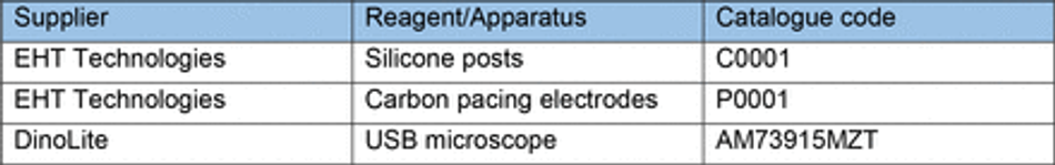
Artificial muscle contractility on 3D print moulded PDMS and commercially available posts54 was achieved via microstimulation using an in-house stimulator system with a pair of autoclaved pacing carbon electrodes (EHT-technology) mounted in the well containing the 3D muscles dipped gently into the media. The stimulator was set to deliver 5 ms bipolar square pulses of 20mV with 0.5Hz frequency. Muscle contraction and post holder movements were recorded over a period of 5 seconds during stimulation via DinoLite Edge microscope (DinoLite) mounted underneath the posts of each device. Analysis of footage was conducted in Imagej using the MuscleMotion plugin.
Immunocytochemistry
After contractility recordings, 3D muscle constructs were fixed in 1% PFA for overnight before removal from posts. Constructs were then permeabilised and blocked for 6 hours in TBS 0.05M (1X) pH7.4, 10% FBS, 1% BSA, 0.5% Triton X-100 at 4°C. Prior to overnight incubation with primary antibodies for Titin and MyoH (Table 10) at 4°C in TBS 0.05M (1X) pH7.4, 1% BSA, 0.5% Triton X-100. The following day constructs were washed 6 times in PBS before overnight incubation with secondary antibodies and DAPI at 4°C in TBS 0.05M (1X) pH7.4, 1% BSA, 0.5% Triton X-100. Finally, constructs were mounted on Brand™ Cavity Slides with Fluoromount G (Thermo) prior to imaging.
Differentiation and directionality analysis
Images of 3D muscle constructs were captured using an inverted Zeiss confocal with a 40x objective. Z-stacks were taken across the constructs and projected using the SUM function in ImageJ. Single images were isolated, and directionality measured from titin signal using the directionality plugin in ImageJ.
Materials
Author Contributions
C.H. and M.Ba. performed and analysed the majority of experiments, from 3D printing establishment and protocol development, cell culture, image acquisition, data analysis and moulds design. C.H., M.Ba., and A.S. wrote the manuscript with feedback from all authors. M.Be. performed Raman spectroscopy experiments and respective data analysis. C.M.G generated a fluorescent motor neuron line used in this project. P.S, K.O’T. contributed to astrocyte and cortical cell culture for the multicellular experiments. V.L. performed culture, stimulation and staining of 3D muscle constructs and collected the images with support from N.K.. N.K. and E.G. contributed to the optimisation of 3D constructs design for muscle tissue engineering. G.K. performed SEM imaging. F.S.T. and A.I. provided feedback on data analysis and manuscript. Resources were provided by A.S., A.I, F.S.T. Funding for this project was provided by A.S.
Supplementary Information
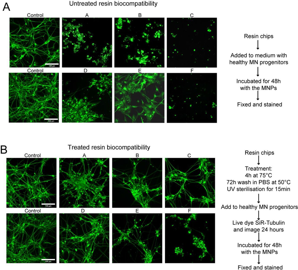
Figure S1:
SLA resins themselves are toxic with and without pre-treatment (A) Chips of 6 resins were added to cultures of motor neuron progenitors pre-stained with SiR – tubulin live dye, incubated for 48 hours before imaging. Representative images of SiR live dye-stained motor neurons after 48 hours in culture with resins compared to 2 control wells. (B) Chips of 6 resins were treated with extra processing steps to improve biocompatibility, bake 4 hours at 75°C, wash in PBS 72 hours at 50°C, UV sterilise 15 mins before being added to cultures of motor neuron progenitors pre- stained with SiR-tubulin cytoskeletal live dye, incubated for 48hrs before imaging. Representative images of SiR live dye-stained motor neurons after 48 hours in culture with treated resins compared to 2 control wells. (C) Representative time lapse videos of SiR live dye-stained motor neurons during the first 24 hours in culture with treated resin chips compared to 2 control wells.
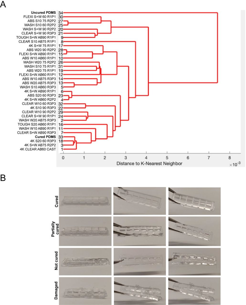
Figure S2:
Quantitation of PDMS curing on 3D printed moulds (A) Dendrogram of the spectral similarity of PDMS casts from 3D printed moulds fabricated with 6 commercially available resins, washed with 5 conditions (S+W = sonicate 10 mins, wash 10 mins, S10 = Sonicate 10 mins, S20 = sonicate 20 mins, W10 = Wash 10 mins, W20 = Wash 20 mins), either untreated or coated with airbrush (AB) and cured at 3 different temperatures (60), (75), (90), compared to samples of uncured and cured PDMS. Replicate and print number (RxPx) for each condition. (B) Heterogeneity of PDMS cast curing from 3D printed moulds by observation ranging from ‘cured’, ‘partially cured’, ‘not cured’, ‘damaged’.
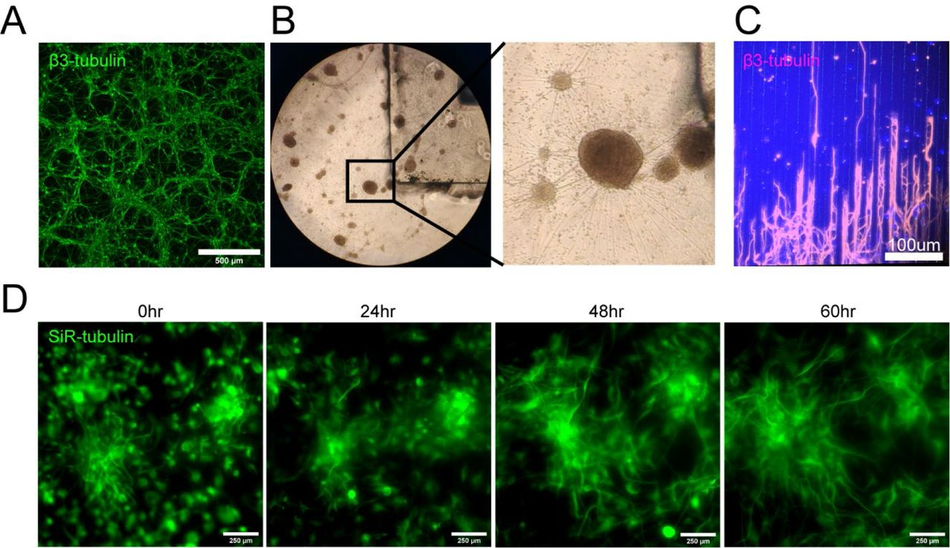
Figure S3:
Biocompatibility of PDMS cast in 3D printed moulds with cells (timelapse and long axons) (A) Representative β-III Tubulin stained differentiated motor neurons cultured on a flat substrate. (B) Brightfield images of differentiated motor neurons with a PDMS cast from a 3D printed mould in the culture medium. (C) β-III Tubulin stained motor neuron long axons seeded on PDMS microfabricated substrate. (D) Snapshots from 60-hour time-lapse of SiR – tubulin live dye stained motor neuron differentiation on PDMS substrate cast in a 3D printed mould.
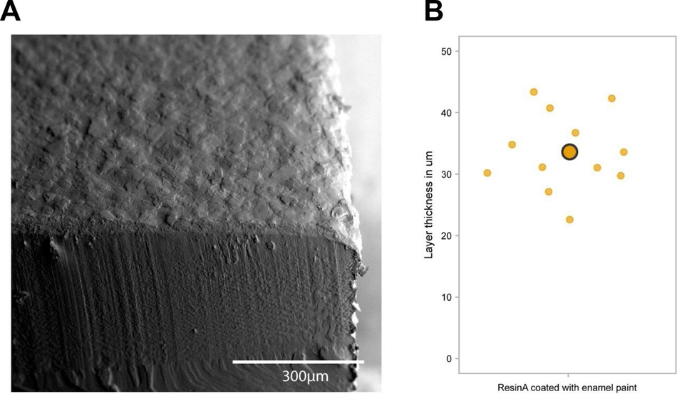
Figure S4:
Analysis of paint layer thickness (A) Representative SEM image of a resin A print with airbrushed enamel paint (B) Analysis of paint layer thickness on 3D SLA printed moulds
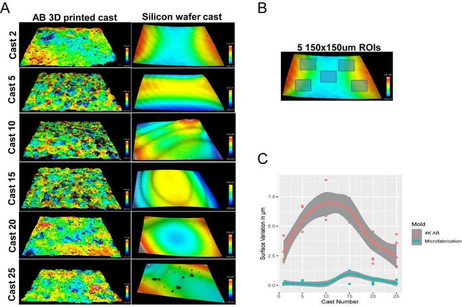
Figure S5:
The surface of SLA 3D prints is rough (A) Representative optical profiles from PDMS casts demoulded from a single airbrushed 3D printed mould and a single microfabricated mould. (B) Representation of 5 ROI selection for quantification of surface roughness on PDMS casts. (C) Quantitation of surface roughness of PDMS casts from the same device over time (25 simultaneous casts) between an airbrushed 3D printed mould and a microfabricated mould.
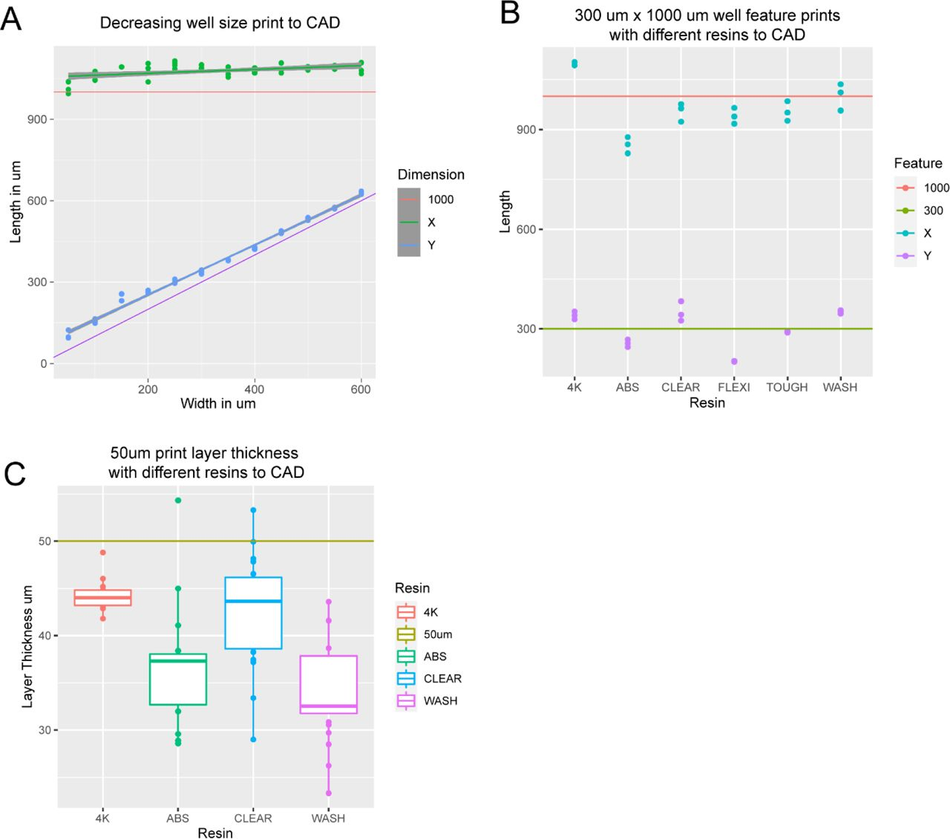
Figure S6:
3D print dimensions are homogenous (A) Graph comparing X and Y dimensions of 3D printed constructs to CAD specifications in a single device with well dimensions ranging from 600 µm x 1000 µm to 50 µm x 1000 µm. (B) Graph comparing X and Y dimensions of 300 µm x 1000 µm features on 3D printed constructs to CAD specifications for 6 commercially available resins printed on 2 SLA 3D printers at manufacturer default settings with a 50 µm layer thickness. (C) Graph comparing the actual layer thickness of 3D printed constructs to CAD specifications for 6 commercially available resins printed on 2 SLA 3D printers at manufacturer default settings with a 50 µm layer thickness.
Non-Plasma devices cannot be used for seeding in microwells (A) Representative SiR-Tubulin images of motor neuron progenitors seeded in microwells ranging from 600 µm x 1000 µm to 50 µm x 1000 µm. Difference in colour indicates depth in focal plane where cells do not reach the micropatterned substrate below.
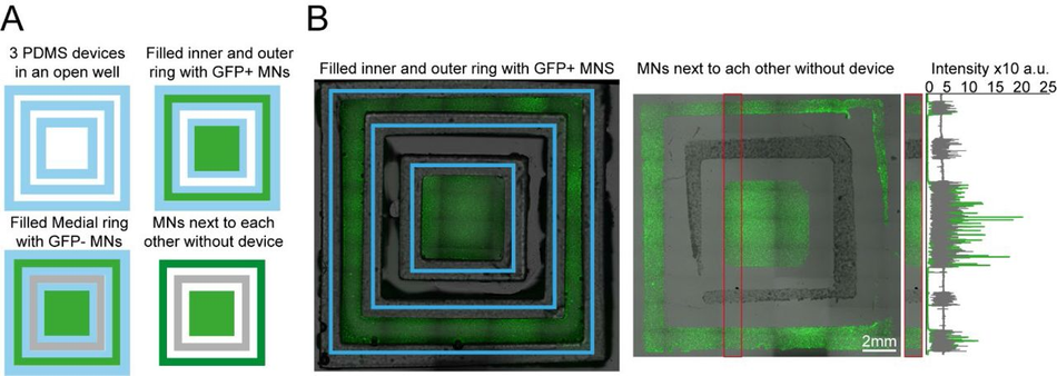
Figure S8:
Plating devices enable manual segregated seeding of different cell types in the same well, device or multiple devices (A) Multiple PDMS casts from 3D printed devices can be seeded in the same well and seeded with different cell types at different time points. Schematic overview of the multi-device protocol for seeding GFP and non GFP+ motor neurons at different time points in 3 devices in the same well. (B) Representative fluorescence images of cells GFP+ motor neurons seeded in the inner and outer rings of the 3 devices and imaged with devices still on (left) and after seeding of the second non-GFP+ motor neurons in the medial ring after device stripping (right), Representative line profile of imaged cell fluorescence showing segregation of individual populations to their designated rings
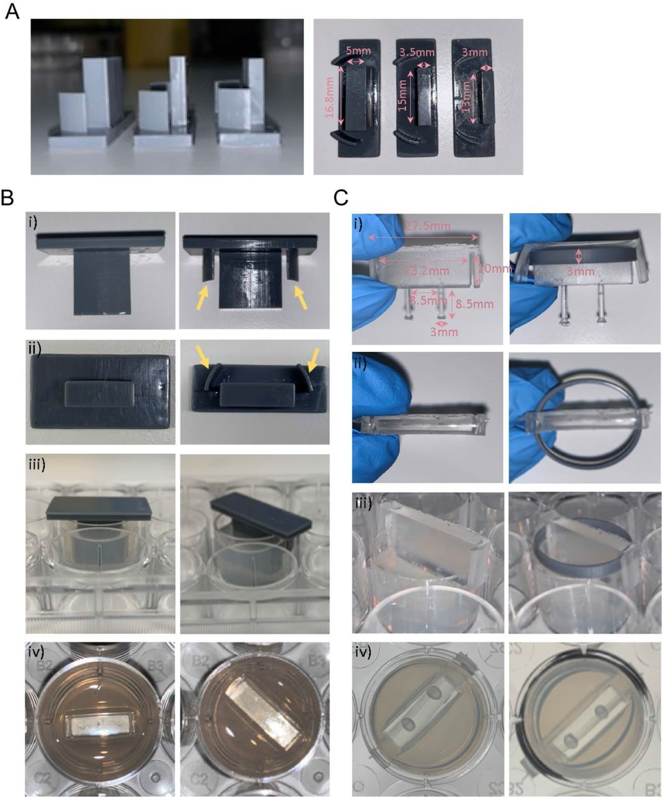
Figure S9:
Optimisation and protocol for 3D muscle culture using PDMS constructs from 3D printed moulds (A) Images show three different mould sizes tested to optimise the volume of the hydrogel mix at a side and bottom view. (Bi-iii) Images showing moulds with (yellow arrows) and without grooves at various perspectives. (Biv) Image shows top view of agarose once mould is removed. (Ci-ii) Images show posts with and without a ring placed underneath the arms from a front and top view. Rings were designed to match the size of one well of a 12-well plate. (Ciii) Images showing posts inserted into agarose moulds at a side view and bottom view from underneath the plate, rings allow posts to be inserted at a specific height.
Acknowledgments
The Serio lab wishes to acknowledge the support of UK Biotechnology and Biological Sciences Research Council [BB/T011572/1] and the Wellcome Trust [213949/Z/18/Z]. Work in the Tedesco lab is supported by the European Research Council (759108 – HISTOID), AFM- Telethon, BBSRC, Muscular Dystrophy and the NIHR (the views expressed are those of the authors and not necessarily those of the National Health Service, the NIHR, or the Department of Health). Human immortalised myoblasts were provided by the Myoline platform of the Institut de Myologie, Paris, France to the Tedesco lab. This research was funded in whole, or in part, by the Wellcome Trust. For the purpose of Open Access, the author has applied a CC BY public copyright licence to any Author Accepted Manuscript version arising from this submission for the work described here.
References
1.↵Gaspard, N. et al. An intrinsic mechanism of corticogenesis from embryonic stem cells. Nature 455, 351–357 (2008).CrossRefPubMedWeb of ScienceGoogle Scholar
2.Ying, Q.-L., Stavridis, M., Griffiths, D., Li, M. & Smith, A. Conversion of embryonic stem cells into neuroectodermal precursors in adherent monoculture. Nat Biotechnol 21, 183–186 (2003).CrossRefPubMedWeb of ScienceGoogle Scholar
3.Amit, M. et al. Clonally Derived Human Embryonic Stem Cell Lines Maintain Pluripotency and Proliferative Potential for Prolonged Periods of Culture. Dev Biol 227, 271–278 (2000).CrossRefPubMedWeb of ScienceGoogle Scholar
4.↵Thomson, J. A. et al. Embryonic Stem Cell Lines Derived from Human Blastocysts. Science 282, 1145–1147 (1998).Abstract/FREE Full TextGoogle Scholar
5.↵Takahashi, K. et al. Induction of Pluripotent Stem Cells from Adult Human Fibroblasts by Defined Factors. Cell 131, 861–872 (2007).CrossRefPubMedWeb of ScienceGoogle Scholar
6.Park, I. H. et al. Reprogramming of human somatic cells to pluripotency with defined factors. Nature 451, 141–146 (2008).CrossRefPubMedWeb of ScienceGoogle Scholar
7.Chanoumidou, K., Mozafari, S., Evercooren, A. B.-V. & Kuhlmann, T. Stem cell derived oligodendrocytes to study myelin diseases. Glia 68, 705–720 (2020).Google Scholar
8.Hasselmann, J. & Blurton-Jones, M. Human iPSC-derived microglia: A growing toolset to study the brain’s innate immune cells. Glia 68, 721–739 (2020).Google Scholar
9.↵Chang, C. Y., et al. Induced pluripotent stem cell (iPSC)-based neurodegenerative disease models for phenotype recapitulation and drug screening. (2020).Google Scholar
10.↵Khadpekar, A. J., Khan, M., Sose, A. & Majumder, A. Low Cost and Lithography-free Stamp fabrication for Microcontact Printing. Sci Rep-uk 9, 1–8 (2019).Google Scholar
11.Li, H. W., Muir, B. V. O., Fichet, G. & Huck, W. T. S. Nanocontact printing: A route to sub-50- nm-scale chemical and biological patterning. Langmuir 19, 1963–1965 (2003).CrossRefWeb of ScienceGoogle Scholar
12.Bhujbal, S. V. et al. Effect of design geometry, exposure energy, cytophilic molecules, cell type and load in fabrication of single-cell arrays using micro-contact printing. Sci Rep-uk 10, 1–13 (2020).Google Scholar
13.↵Lee, K.-B., Kim, D. J., Lee, Z.-W., Woo, S. I. & Choi, I. S. Pattern generation of biological ligands on a biodegradable poly(glycolic acid) film. Langmuir Acs J Surfaces Colloids 20, 2531–5 (2004).Google Scholar
14.↵Carraro, A. et al. In vitro analysis of a hepatic device with intrinsic microvascular-based channels. Biomed Microdevices 10, 795–805 (2008).CrossRefPubMedWeb of ScienceGoogle Scholar
15.Park, J. W., Vahidi, B., Taylor, A. M., Rhee, S. W. & Jeon, N. L. Microfluidic culture platform for neuroscience research. Nat Protoc 1, 2128–2136 (2006).CrossRefPubMedWeb of ScienceGoogle Scholar
16.Nguyen, T. A., Yin, T. I., Reyes, D. & Urban, G. A. Microfluidic chip with integrated electrical cell-impedance sensing for monitoring single cancer cell migration in three-dimensional matrixes. Anal Chem 85, 11068–11076 (2013).CrossRefGoogle Scholar
17.Wang, Y., Wang, L., Zhu, Y. & Qin, J. Human brain organoid-on-a-chip to model prenatal nicotine exposure. Lab Chip 18, 851–860 (2018).CrossRefPubMedGoogle Scholar
18.Wang, Y. I., Abaci, H. E. & Shuler, M. L. Microfluidic blood–brain barrier model provides in vivo-like barrier properties for drug permeability screening. Biotechnol Bioeng 114, 184–194 (2017).CrossRefGoogle Scholar
19.↵Whitesides, G. M. The origins and the future of microfluidics. Nature 442, 368–373 (2006).CrossRefPubMedWeb of ScienceGoogle Scholar
20.↵Weibel, D. B., Diluzio, W. R. & Whitesides, G. M. Microfabrication meets microbiology. Nat Rev Microbiol 5g, 209–18 (2007).CrossRefPubMedWeb of ScienceGoogle Scholar
21.↵Qin, D., Xia, Y. & Whitesides, G. M. Soft lithography for micro- and nanoscale patterning. Nat Protoc 5, 491–502 (2010).CrossRefPubMedGoogle Scholar
22.↵Saggiomo, V. & Velders, A. H. Simple 3D Printed Scaffold-Removal Method for the Fabrication of Intricate Microfluidic Devices. Adv Sci 2, 1500125 (2015).Google Scholar
23.Fichou, D. & Morlock, G. E. Open-Source-Based 3D Printing of Thin Silica Gel Layers in Planar Chromatography. Anal Chem 89, 2116–2122 (2017).Google Scholar
24.Rosario, M. D., Heil, H. S., Mendes, A., Saggiomo, V. & Henriques, R. The Field Guide to 3D Printing in Optical Microscopy for Life Sciences. Adv Biology e2100994 (2021) doi:10.1002/adbi.202100994.CrossRefGoogle Scholar
25.Baas, S. & Saggiomo, V. Ender3 3D printer kit transformed into open, programmable syringe pump set. Hardwarex 10, e00219 (2021).Google Scholar
26.Diederich, B. et al. A versatile and customizable low-cost 3D-printed open standard for microscopic imaging. Nat Commun 11, 5979 (2020).Google Scholar
27.↵Collins, J. T. et al. Robotic microscopy for everyone: the OpenFlexure microscope. Biomed Opt Express 11, 2447 (2020).Google Scholar
28.↵Balakrishnan, H. K. et al. 3D Printing: An Alternative Microfabrication Approach with Unprecedented Opportunities in Design. Anal Chem 93, 350–366 (2021).Google Scholar
29.↵Waheed, S. et al. 3D printed microfluidic devices: enablers and barriers. Lab Chip 16, 1993–2013 (2016).CrossRefPubMedGoogle Scholar
30.↵Bhattacharjee, N., Parra-Cabrera, C., Kim, Y. T., Kuo, A. P. & Folch, A. Desktop- Stereolithography 3D-Printing of a Poly(dimethylsiloxane)-Based Material with Sylgard-184 Properties. Adv Mater 30, e1800001 (2018).Google Scholar
31.↵Phrozen Sonic Mini 4K - 3DJake UK-https://www.3djake.uk/phrozen/sonic-mini-4k?gclid=Cj0KCQiAxc6PBhCEARIsAH8Hff0V1kZ0Ttq1RbiwsAtaU6Er7Aw3MK7xu6BFaIyEeOylD8TOYQjX9e4aAgqoEALw_wcB-2022-01-28.Google Scholar
32.↵Zortrax Raydent Crown & Bridge Resin - 3DJake UK-https://www.3djake.uk/zortrax/raydent-crown-bridge-resin-2022-01-28.Google Scholar
33.↵Oskui, S. M. et al. Assessing and Reducing the Toxicity of 3D-Printed Parts. Environ Sci Tech Let 3, 1–6 (2016).Google Scholar
34.Kownacki, I. et al. Effect of triorganophosphites on platinum catalyzed curing of silicon rubber. Appl Catal Gen 362, 106–114 (2009).Google Scholar
35.Bail, R. et al. The Effect of a Type I Photoinitiator on Cure Kinetics and Cell Toxicity in Projection-Microstereolithography. Proc Cirp 5, 222–225 (2013).Google Scholar
36.↵Ikemura, K., Ichizawa, K., Yoshida, M., Ito, S. & Endo, T. UV-VIS spectra and photoinitiation behaviors of acylphosphine oxide and bisacylphosphine oxide derivatives in unfilled, light-cured dental resins. Dent Mater J 27, 765–74 (2008).PubMedGoogle Scholar
37.↵Ferraz, M. de A. M. M., Nagashima, J. B., Venzac, B., Gac, S. L. & Songsasen, N. 3D printed mold leachates in PDMS microfluidic devices. Sci Rep-uk 10, 994 (2020).Google Scholar
38.↵Venzac, B. et al. PDMS Curing Inhibition on 3D-Printed Molds: Why? Also, How to Avoid It? Anal Chem 93, 7180–7187 (2021).Google Scholar
39.Bazaz, S. R. et al. Rapid Softlithography Using 3D-Printed Molds. Adv Mater Technologies 4, 1900425 (2019).Google Scholar
40.↵Comina, G., Suska, A. & Filippini, D. PDMS lab-on-a-chip fabrication using 3D printed templates. Lab Chip 14, 424–430 (2013).Google Scholar
41.↵Chande, C. et al. Universal method for fabricating PDMS microfluidic device using SU8, 3D printing and soft lithography. Technology 08, 50–57 (2020).Google Scholar
42.↵O’Grady, B. J. et al. Rapid Prototyping of Cell Culture Microdevices Using Parylene-Coated 3D Prints. Biorxiv 2021.08.02.454773 (2021) doi:10.1101/2021.08.02.454773.Abstract/FREE Full TextGoogle Scholar
43.↵Wright, D. et al. Reusable, reversibly sealable parylene membranes for cell and protein patterning. J Biomed Mater Res A 85A, 530–538 (2008).Google Scholar
44.↵Messner, J. J., Glenn, H. L. & Meldrum, D. R. Laser-fabricated cell patterning stencil for single cell analysis. Bmc Biotechnol 17, 89 (2017).Google Scholar
45.↵Sahni, G., Yuan, J. & Toh, Y.-C. Stencil Micropatterning of Human Pluripotent Stem Cells for Probing Spatial Organization of Differentiation Fates. J Vis Exp Jove (2016) doi:10.3791/54097.CrossRefGoogle Scholar
46.↵Hagemann, C. et al. “Axonal Length Determines distinct homeostatic phenotypes in human iPSC derived motor neurons on a bioengineered platform.” Biorxiv 2021.08.30.458271 (2021) doi:10.1101/2021.08.30.458271.Abstract/FREE Full TextGoogle Scholar
47.↵Shi, Y., Kirwan, P. & Livesey, F. J. Directed differentiation of human pluripotent stem cells to cerebral cortex neurons and neural networks. Nat Protoc 7, 1836–1846 (2012).CrossRefPubMedGoogle Scholar
48.↵Serio, A. et al. Astrocyte pathology and the absence of non-cell autonomy in an induced pluripotent stem cell model of TDP-43 proteinopathy. Proc National Acad Sci 110, 4697–4702 (2013).Abstract/FREE Full TextGoogle Scholar
49.↵Sen, D., Voulgaropoulos, A. & Keung, A. J. Effects of early geometric confinement on the transcriptomic profile of human cerebral organoids. Bmc Biotechnol 21, 59 (2021).Google Scholar
50.↵Bauwens, C. L. et al. Control of Human Embryonic Stem Cell Colony and Aggregate Size Heterogeneity Influences Differentiation Trajectories. Stem Cells 26, 2300–2310 (2008).CrossRefPubMedWeb of ScienceGoogle Scholar
51.↵Hwang, Y.-S. et al. Microwell-mediated control of embryoid body size regulates embryonic stem cell fate via differential expression of WNT5a and WNT11. Proc National Acad Sci 106, 16978– 16983 (2009).Abstract/FREE Full TextGoogle Scholar
52.↵Hansen, A. et al. Development of a Drug Screening Platform Based on Engineered Heart Tissue. Circ Res 107, 35–44 (2010).Abstract/FREE Full TextGoogle Scholar
53.↵Maffioletti, S. M. et al. Three-Dimensional Human iPSC-Derived Artificial Skeletal Muscles Model Muscular Dystrophies and Enable Multilineage Tissue Engineering. Cell Reports 23, 899–908 (2018).Google Scholar
54.↵eht-technologies-https://www.eht-technologies.com/products.html-2022-01-28.
55.↵Ataee, A., Li, Y. & Wen, C. A comparative study on the nanoindentation behavior, wear resistance and in vitro biocompatibility of SLM manufactured CP–Ti and EBM manufactured Ti64 gyroid scaffolds. Acta Biomater 97, 587–596 (2019).Google Scholar
56.↵Choi, H. K., Kim, C.-H., Lee, S. N., Kim, T.-H. & Oh, B.-K. Nano-sized graphene oxide coated nanopillars on microgroove polymer arrays that enhance skeletal muscle cell differentiation. Nano Convergence 8, 40 (2021).Google Scholar
57.↵Otomo, A. et al. Efficient differentiation and polarization of primary cultured neurons on poly(lactic acid) scaffolds with microgrooved structures. Sci Rep-uk 10, 6716 (2020).Google Scholar
58.↵Rizki-Safitri, A. et al. Efficient functional cyst formation of biliary epithelial cells using microwells for potential bile duct organisation in vitro. Sci Rep-uk 8, 11086 (2018).Google Scholar
59.↵Osaki, T., Shin, Y., Sivathanu, V., Campisi, M. & Kamm, R. D. In Vitro Microfluidic Models for Neurodegenerative Disorders. Adv Healthc Mater 7, 1700489 (2018).Google Scholar
60.↵Zhang, S., Wan, Z. & Kamm, R. D. Vascularized organoids on a chip: strategies for engineering organoids with functional vasculature. Lab Chip 21, 473–488 (2021).Google Scholar
61.↵Chan, H. N. et al. Direct, one-step molding of 3D-printed structures for convenient fabrication of truly 3D PDMS microfluidic chips. Microfluid Nanofluid 19, 9–18 (2015).Google Scholar
62.↵Hart, C., Didier, C. M., Sommerhage, F. & Rajaraman, S. Biocompatibility of Blank, Post- Processed and Coated 3D Printed Resin Structures with Electrogenic Cells. Biosensors 10, 152 (2020).Google Scholar
63.↵Waheed, S. et al. Enhanced physicochemical properties of polydimethylsiloxane based microfluidic devices and thin films by incorporating synthetic micro-diamond. Sci Rep-uk 7, 15109 (2017).Google Scholar
64.↵Wang, L., Sun, B., Ziemer, K. S., Barabino, G. A. & Carrier, R. L. Chemical and physical modifications to poly(dimethylsiloxane) surfaces affect adhesion of Caco-2 cells. J Biomed Mater Res A 93A, 1260–1271 (2010).Google Scholar
65.↵Hoffmann, A. et al. New stereolithographic resin providing functional surfaces for biocompatible three-dimensional printing. J Tissue Eng 8, 2041731417744485 (2017).Google Scholar
66.Bacha, T. W., Manuguerra, D. C., Marano, R. A. & Stanzione, J. F. Hydrophilic modification of SLA 3D printed droplet generators by photochemical grafting. Rsc Adv 11, 21745–21753 (2021).Google Scholar
67.↵Urrios, A. et al. 3D-printing of transparent bio-microfluidic devices in PEG-DA. Lab Chip 16, 2287–2294 (2016).Google Scholar
68.↵Toepke, M. W. & Beebe, D. J. PDMS absorption of small molecules and consequences in microfluidic applications. Lab Chip 6, 1484–1486 (2006).CrossRefPubMedWeb of ScienceGoogle Scholar
69.Meer, B. J. van, et al. Small molecule absorption by PDMS in the context of drug response bioassays. Biochem Bioph Res Co 482, 323–328 (2017).CrossRefGoogle Scholar
70.↵Regehr, K. J. et al. Biological implications of polydimethylsiloxane-based microfluidic cell culture. Lab Chip 9, 2132–2139 (2009).CrossRefPubMedWeb of ScienceGoogle Scholar
71.↵Hall, C. E. et al. Progressive Motor Neuron Pathology and the Role of Astrocytes in a Human Stem Cell Model of VCP-Related ALS. Cell Reports 19, 1739–1749 (2017).Google Scholar
72.↵Fusion 360 | 3D CAD, CAM, CAE & PCB Cloud-Based Software | Autodesk. https://www.autodesk.com/products/fusion-360/overview.Google Scholar
73.↵Tinkercad | Create 3D digital designs with online CAD | Tinkercad. https://www.tinkercad.com/.Google Scholar
74.↵Gopal, S. et al. Biointerfaces: Porous Silicon Nanoneedles Modulate Endocytosis to Deliver Biological Payloads (Adv. Mater. 12/2019). Adv Mater 31, 1970086 (2019).Google Scholar
75.↵Schindelin, J. et al. Fiji: an open-source platform for biological-image analysis. Nat Methods 9, 676–682 (2012).CrossRefPubMedWeb of ScienceGoogle Scholar
76.↵Goedhart, J. SuperPlotsOfData—a web app for the transparent display and quantitative comparison of continuous data from different conditions. Mol Biol Cell 32, 470–474 (2021).CrossRefGoogle Scholar
77.↵Hansen, A. et al. Development of a Drug Screening Platform Based on Engineered Heart Tissue. Circ Res 107, 35–44 (2010).Abstract/FREE Full TextGoogle Scholar
About the University Technology Exposure Program 2022
Wevolver, in partnership with Mouser Electronics and Ansys, is excited to announce the launch of the University Technology Exposure Program 2022. The program aims to recognize and reward innovation from engineering students and researchers across the globe. Learn more about the program here.